
 Open Access Article
 This Open Access Article is licensed under a Creative Commons Attribution-Non Commercial 3.0 Unported Licence
Mechanochemical pretreatment of tin iodide perovskite precursors: effects of grinding temperature and time on solar cell performance†
Tingting
Liu
 a,
Sungwoon
Cho
a,
Ryosuke
Nishikubo
ab,
Mikhail
Pylnev
a,
Fumitaka
Ishiwari
abc,
Atsushi
Wakamiya
d and
Akinori
Saeki
*ab
a,
Sungwoon
Cho
a,
Ryosuke
Nishikubo
ab,
Mikhail
Pylnev
a,
Fumitaka
Ishiwari
abc,
Atsushi
Wakamiya
d and
Akinori
Saeki
*ab
aDepartment of Applied Chemistry, Graduate School of Engineering, Osaka University, 2-1 Yamadaoka, Suita, Osaka 565-0871, Japan. E-mail: saeki@chem.eng.osaka-u.ac.jp
bInnovative Catalysis Science Division, Institute for Open and Transdisciplinary Research Initiatives (ICS-OTRI), Osaka University, 1-1 Yamadaoka, Suita, Osaka 565-0871, Japan
cPRESTO, Japan Science and Technology Agency (JST), Kawaguchi, Saitama 332-0012, Japan
dInstitute for Chemical Research, Kyoto University, Uji, Kyoto 611-0011, Japan
First published on 23rd January 2025
Abstract
Tin-based halide perovskite solar cells (Sn PSCs) have unacceptably low open-circuit voltages owing to the severe carrier traps induced by the facile oxidation of Sn2+. To prevent oxidation, Sn powder is often added to the precursor solutions; however, the optimal process conditions and the detailed underlying mechanism remain elusive. Here, the PSC precursors (Sn powder, SnF2, SnI2, and organic cation iodides) are subjected to mechanochemical pretreatment to enhance the power conversion efficiency (PCE) of PEA0.1FA0.9SnI3 PSCs (PEA: phenylethylammonium and FA: formamidinium). Two systems are compared: the Sn powder–SnF2 (Sn–SnF2) system and all-chemical system, both ground using a vibrational ball-milling technique. The grinding temperature (5–28 °C) and duration (0.5–9 h) are found to significantly affect the PCEs. The processes with 4 h of grinding of Sn–SnF2 at 13 °C followed by 1 h of thermal annealing (TA) at 170 °C and 2 h of grinding of the all-chemical sample without TA yield the highest PCEs of 7.76 and 7.60%, respectively, compared to 5.24% for the control (no grinding). The assumed mechanochemical reactions provide a rationale for the preferred low-temperature grinding process. An efficient and reliable method with accelerated reduction of SnI4 in dimethyl sulfoxide and improved oxygen tolerance of Sn PSCs, both resulting from grinding, is proposed for the preparation of lead-free PSCs.
Broader contextTin (Sn) halide perovskites are among the most promissing lead-free semiconductors for perovskite solar cell (PSC) applications. Despite their potential optoelectronic properties, they are prone to easy oxidation, leading to a loss of open-circuit voltage and power conversion efficiency (PCE). To address this oxidation issue, SnF2 is often incorporated into perovskite precursor solutions together with Sn powder. However, the optimal process conditions and details of the underlying role of these anti-oxidants have remained largely unexplored. For the first time, we report the mechanochemical pretreatment of the precursors (Sn powder, SnF2, SnI2, and organic cation iodides) to improve the PCE of Sn PSCs. Importantly, grinding temperature and time are found to significantly affect the PSC performance, which is rationalized by the fundamental thermodynamics of involved reactions. Our work has led to the development of a reliable and reproducible method to fabricate Sn PSCs and offers a thermodynamics-based strategy toward efficient lead-free PSCs. |
Introduction
As sunlight is the most abundant source of renewable energy, the development of high efficiency and cost-effective photovoltaics (PV) with long-term stability is vital for realizing a carbon-neutral society.1,2 In recent years, organic–inorganic metal halide perovskite solar cells (PSCs) with the general perovskite formula ABX3, where A = formamidinium (FA), phenethylammonium (PEA) and methylammonium (MA), B = Pb2+ and Sn2+, and X = I−, Br−, and Cl− have become the shining star of PV technology owing to their superior optoelectronic properties as well as their affordability and straightforward production.3–6 The power conversion efficiencies (PCEs) of single junction lead-based PSCs have increased rapidly in the past decades to reach the current maximum of 26%.7–10 However, because the toxicity of Pb may limit the commercialization of this technology, several efforts have been made to replace Pb with other less toxic metals (e.g., Sn, Bi, Sb, Ge, and Cu).11–17In particular, Sn is regarded as the most promising substitute for lead18–21 owing to its superior photophysical properties including a bandgap (1.2–1.4 eV) closer to the ideal value of 1.34 eV at the peak of the Shockley–Queisser efficiency curve compared to Pb-perovskites with a bandgap range of 1.5–2.3 eV.22,23 Despite the significant increase, the highest PCE that has ever been reported for Sn-PSCs, ∼15% (Table S1 (ESI†)),24–30 is still far below their theoretical maximum value. The single major factor responsible for the PCE deficit is the significant open-circuit voltage (VOC) losses, primarily induced by nonradiative recombination at traps intrinsically resulting from the facile oxidation of Sn2+ through Sn4+ + 2e− → Sn2+ (E0 = +0.15 V) compared to Pb4+ + 2e− → Pb2+ (E0 = +1.67 V), where E0 is the standard redox potential.
SnF2 is generally utilized as an additive in the precursor solution of Sn PSCs as an effective approach to eliminate the oxidized state of Sn4+.31–33 The inhibition of the oxidation of Sn2+ can be interpreted through the constraint of the two-phase coexistence of the perovskite and SnF2, which facilitates an increase in the chemical potential of Sn and the formation energy of Sn vacancies.34,35 Another view is that SnF2 has the ability to reduce undesired species such as SnI4 and I2 by isolating them from the perovskite environment through ligand exchange36 or by forming a thermodynamically stable mixed-valence Sn3F8 phase.37 Other than this, metallic Sn is sometimes used as a reducing agent through the Sn4+ + Sn → 2Sn2+ reaction, where Sn powder38–41 or in situ-prepared Sn particles42 are simply added to the precursor solution, stirred for 1–4 h, and then removed by filtration. Although this reductive reaction was clearly observed in a SnI4 solution containing Sn powder,38 little is known about the role of Sn powder in actual perovskite precursor solutions or under optimal processing conditions. Moreover, Sn-PSCs are considerably sensitive to the environment (temperature, vapor, small amounts of oxygen and water, etc. in a glove box), which complicates the fabrication of Sn-PSCs for scientific research and commercialization.
In this paper, we report a ball-milling process of Sn powder with SnF2 and the Sn-PSC precursors (SnI2, FAI, and PEAI), which enables mechanochemical reactions under controlled conditions (frequency in hertz, reaction time, and temperature) and facilitates the removal of Sn4+. The mechanochemical reaction has drawn much attention in this decade because it offers a unique approach to synthesize chemical compounds without a solvent.43,44 Although the mechanochemical synthesis of organic–inorganic lead perovskites is well known,45–47 the mechanical pretreatment of Sn powder and Sn-PSC precursors remains unexplored. Some examples of mechanochemical synthesis of Sn (pseudo-)perovskites are ASnX3 (A = Cs, MA, or FA; X = I and Br),48,49 MASnBr3 (ref. 50) and A2SnI6 (ref. 51) without using oxidative solvents.52 The antioxidative effect of SnF2 is also reported in the ground Sn perovskite.48 As schematized in process (1) of Fig. 1, we examined two systems: 1. Sn powder and SnF2 and 2. a mixture of all the PSC chemicals including Sn powder, SnF2, SnI2, FAI, and PEAI. A still image of a ball mill system with a hand-made temperature control box (vide infra) is presented in Fig. S1 (ESI).† The perovskite formula used throughout this work is PEA0.1FA0.9SnI3. The chemicals in each of these two systems were sealed in a metal vessel under a N2 atmosphere and subjected to mechanical vibrations using a ball mill facility at a frequency of 30 Hz. Although this pretreatment could be conducted by manual grinding with a mortar and pestle, the ball mill facility allows for facile processing and accurate control of the grinding conditions. After grinding, the samples were either thermally annealed (TA) at 170 °C for 1 h or used without annealing. Subsequently the Sn-PSC precursor and ground powder were dissolved/suspended in dimethyl sulfoxide (DMSO) and stirred at 45 °C for 2.5 h, filtered (process (2) in Fig. 1), and used for spin-coating via a hot anti-solvent treatment (HAT,53 65 °C toluene) method (process (3) in Fig. 1). We examined the effects of pretreatment from the perspective of the grinding time and temperature to assess the extent to which the underlying mechanochemical reaction affects the PCE of the Sn-PSCs.
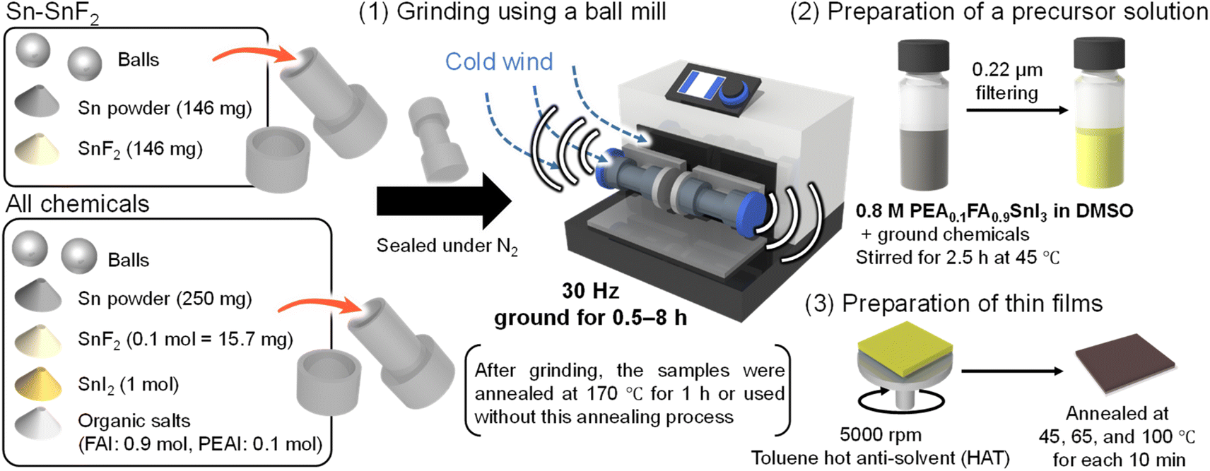 | ||
| Fig. 1 Schematic of the grinding process of Sn perovskite precursors in this study. After placing two balls and the Sn–SnF2 system (Sn powder and SnF2) or the all-chemical system (Sn powder, SnF2, SnI2, and organic salts) into the milling vessel, they were subjected to (1) grinding using a ball mill facility at 30 Hz, (2) preparation of the precursor solution with filtering, and (3) preparation of the thin films. See Fig. S1 (ESI†) for the temperature control of ball milling. | ||
Results and discussion
Grinding time dependence at room temperature
We examined the grinding-time dependence (0.5–9 h) of both the Sn–SnF2 and all-chemical systems with/without TA. In this first examination, the grinding temperature was not controlled. Using the process shown in Fig. 1 to prepare the Sn perovskite, we fabricated inverted (p–i–n) PSC devices with a layered structure comprising glass, indium tin oxide (ITO), poly(3,4-ethylenedioxythiophene): poly(4-styrenesulfonate) (PEDOT: PSS), PEA0.1FA0.9SnI3, fullerene (C60, evaporated), bathocuproine (BCP, evaporated), and silver (Ag, evaporated). As shown in Fig. 2a, the PCE values for the Sn–SnF2 system gradually increased with the grinding time from PCE = 3.64% at 0 h (control, no grinding) to 5.54% at 4 h. The highest PCE was achieved when TA was used in addition to grinding, whereas extension of the grinding time to 5 h without TA increased the PCE to 5.33%, almost the same as with TA. The same trend was observed for the all-chemical system without TA (Fig. 2b), although the optimal grinding time was longer (8 h) than that of the Sn–SnF2 system, and the highest PCE was slightly higher at 5.81%. The improvements are mainly attributed to the increase in the VOC from 0.296 (control) to 0.417 (Sn–SnF2) and 0.467 V (all-chemical system) (Fig. S2 (ESI†)). Other device parameters (the short-circuit current density: JSC and fill factor [FF]) are listed in Tables S2 and S3 (ESI†) and their current density (J)–voltage (V) curves are shown in Fig. S3 (ESI†). In contrast, the ground all-chemical system with TA exhibited a decreasing dependence on the grinding time, which was caused by a significant suppression of the JSC. This degradation may be caused by the decomposition and/or evaporation of precursor compounds at high TA temperatures.54,55 | ||
| Fig. 2 PCE vs. grinding time for the (a) Sn–SnF2 and (b) all-chemical systems ground at room temperature. The black solid circles connected by black lines and open triangles connected with gray lines represent preparation of the ground powder without and with the TA process, respectively, at 170 °C for 1 h. The red and green circles in (a) and (b) indicate the highest PCE, the details of which are evaluated in Fig. 3. | ||
The effect of the pretreatments on the multicrystalline morphology was investigated by scanning electron microscopy (SEM) of the PEA0.1FA0.9SnI3 layers fabricated from the Sn–SnF2 and all-chemical samples prepared using the optimal grinding times (marked with red and green circles in Fig. 2, respectively). As shown in Fig. 3a, the control film (no grinding) has poor film coverage and irregular grain shapes with a few pinholes. In comparison, the Sn–SnF2-treated film had noticeably improved, exhibiting pinhole-free large grains that were partially inhomogeneous in size (Fig. 3b). In contrast, the ground all-chemical system exhibited small but uniform particles (Fig. 3c). We examined the photophysical properties of these films by performing photoabsorption (PA) spectroscopy (Fig. 3d), Urbach energy (EU) calculations from the PA spectra (Fig. 3e), photoluminescence (PL) spectroscopy (Fig. 3f), and time-resolved PL (TRPL) measurements (Fig. 3g) for the Sn perovskite films prepared using the control, ground Sn–SnF2, and ground all-chemical systems. Their absorbance intensity at the edge increased in this order, and the bandgap energies (Eg) decreased from 1.51 to 1.43 and 1.42 eV (the Tauc plot is presented in Fig. S4 (ESI†)). The larger Eg of the control than those of the latter ground systems (their Egs are consistent with the literature) is possibly caused by light scattering due to a coarse morphology and high density trap states at the band edge, as discussed in the literature.56 Similarly, the EUs decreased from 58.0 to 37.6 and 32.5 meV, the PL intensities increased by 1.0-fold (normalized), 1.2-fold, and 2.9-fold, and the PL lifetimes increased from 375 to 516 and 560 ps, respectively (Table S4 (ESI†)). Although these lifetimes are shorter than those reported in previous studies (∼1270 ps),25,57 the photophysical properties are consistent with the device performance, indicating the effectiveness of introducing grinding as pretreatment. Presumably, the increase in the PCE of the Sn–SnF2 system is attributable to its improved multicrystalline morphology, whereas that of the all-chemical system is due to its enhanced photophysical properties.
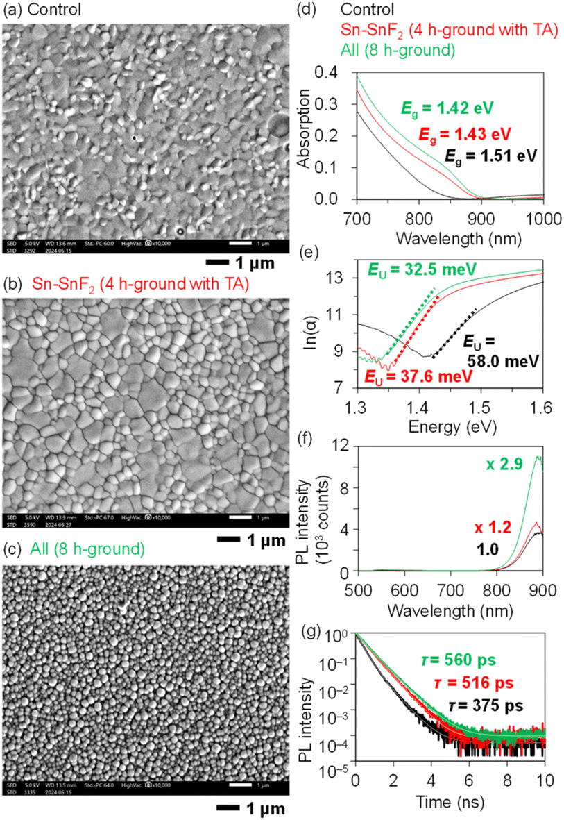 | ||
| Fig. 3 SEM images of PEA0.1FA0.9SnI3 films on PEDOT: PSS processed with the (a) control Sn powder (no grinding) and (b) Sn–SnF2 system ground for 4 h followed by TA, and (c) all-chemical system ground for 8 h. These films (black, red, and green, respectively) were subjected to the following measurements. (d) Photoabsorption spectra (the photoabsorption in the near-infrared region is due to PEDOT: PSS). (e) ln(α) vs. photon energy to calculate EU (the values are appended). (f) Steady-state PL spectra (λex = 500 nm). (g) TRPL decays of quartz/PSS/Sn perovskite/PMAA (λex = 377 nm; λem = 800 nm). | ||
The regulation of the perovskite crystal size and grain orientation was explored using X-ray diffraction (XRD) (Fig. S5 (ESI†)). Compared with the control film, the intensities of the (100) and (200) peaks of the Sn perovskite film processed with ground Sn–SnF2 increased dramatically, whereas that of the (111) peak decreased slightly. However, the (100) and (200) peak intensities of the Sn perovskite films processed with the all-chemical system decreased markedly, whereas that of the (111) peak increased. These changes indicate an enhancement in the crystallinity and orientation in the (100) direction due to Sn–SnF2 grinding.
Reduction of SnI4 in solution
We examined the rate of Sn4+ reduction by adding Sn–SnF2 powder (that had been prepared with different grinding times) to a solution of 0.8 M SnI4/FAI (molar ratio 1![[thin space (1/6-em)]](https://www.rsc.org/images/entities/char_2009.gif) :1) in DMSO to trace the change in the PA spectra. During this measurement, we noticed that the PA spectra of SnIx/FAI (x = 2 or 4) were blue-shifted with decreasing concentration (Fig. S6 (ESI†)). Therefore, we adopted a high concentration relevant to the device preparation (0.8 M) using a cell with a short optical length (2 mm) and focused on the change in the PA edge. As shown in the still images of the solutions in Fig. 4a, the red-black colour of SnI4 spontaneously changed to the yellow colour of SnI2 within 2–5 min. The rate of the colour change for the solution processed with the ground powder was higher than that processed with nonground Sn–SnF2 (control). The PA spectra after 2 min of reduction and filtration (Fig. 4b) clearly exhibit a faster blueshift (reduction of Sn4+) in the Sn–SnF2-processed SnI4/FAI solution than the control (the PA spectra recorded at 5, 10, 20, and 30 min are provided in Fig. S7 (ESI†)). Fig. 4c shows the temporal change in the PA edge with reaction time for different grinding times (1–6 h) with/without TA, along with its magnification in the inset. All of the PA edge energies rapidly increased from the initial 1.91 eV of the 0.8 M SnI4/FAI to 2.70 eV of the 0.8 M SnI2/FAI solution (dotted line in Fig. 4c) within 10 min. After 5 min of reaction, all the solutions processed with ground Sn–SnF2 turned light yellow, and the PA edge of the non-ground solution lagged behind that of the treated solution. Thus, we suggest that the preparation of Sn–SnF2 through grinding has an impact on the acceleration of the SnI4 reduction.
:1) in DMSO to trace the change in the PA spectra. During this measurement, we noticed that the PA spectra of SnIx/FAI (x = 2 or 4) were blue-shifted with decreasing concentration (Fig. S6 (ESI†)). Therefore, we adopted a high concentration relevant to the device preparation (0.8 M) using a cell with a short optical length (2 mm) and focused on the change in the PA edge. As shown in the still images of the solutions in Fig. 4a, the red-black colour of SnI4 spontaneously changed to the yellow colour of SnI2 within 2–5 min. The rate of the colour change for the solution processed with the ground powder was higher than that processed with nonground Sn–SnF2 (control). The PA spectra after 2 min of reduction and filtration (Fig. 4b) clearly exhibit a faster blueshift (reduction of Sn4+) in the Sn–SnF2-processed SnI4/FAI solution than the control (the PA spectra recorded at 5, 10, 20, and 30 min are provided in Fig. S7 (ESI†)). Fig. 4c shows the temporal change in the PA edge with reaction time for different grinding times (1–6 h) with/without TA, along with its magnification in the inset. All of the PA edge energies rapidly increased from the initial 1.91 eV of the 0.8 M SnI4/FAI to 2.70 eV of the 0.8 M SnI2/FAI solution (dotted line in Fig. 4c) within 10 min. After 5 min of reaction, all the solutions processed with ground Sn–SnF2 turned light yellow, and the PA edge of the non-ground solution lagged behind that of the treated solution. Thus, we suggest that the preparation of Sn–SnF2 through grinding has an impact on the acceleration of the SnI4 reduction.
 | ||
| Fig. 4 (a) Still image of a DMSO solution of 0.8 M SnI4 and FAI in the left panel. This solution was processed using the control (Sn–SnF2 without grinding) and treated (ground Sn–SnF2 for 4 h) powder for 2 min, filtered, and their photographs were taken (centre panel). Those after 5 min of processing are shown in the panel on the right. (b) Photoabsorption spectra of the DMSO solutions of 0.8 M SnI4 and FAI processed with the Sn–SnF2 system for 2 min. The colour represents the grinding time (black: control = no grinding, colour: 1–6 h) with/without TA. (c) Change in PA edge of the solutions with the reductive time (stirring with Sn–SnF2 powder). Many of the solid and dotted lines are overlapped. | ||
Particle morphology and crystallography after grinding
In addition to the mechanochemical reaction that occurs as a result of grinding (details are discussed in the next section), the change in particle morphology caused by grinding may be another factor influencing the reductive reaction. The Sn–SnF2 mixtures that were ground to a powder for 0.5–2 h have a grey appearance (Fig. S8a (ESI†)), whereas those ground for 3–6 h appear dark grey (Fig. S8b (ESI†)). Subsequent to grinding, the TA process seemed to accelerate the colour change from grey to dark grey. In contrast, the ground all-chemical powders were black, indicating the formation of Sn perovskite (Fig. S8c (ESI†)). It is noteworthy that the excessive fusion of particles does not occur in these samples, whereas this happened when only Sn powder was ground (Fig. S8d (ESI†)). Images of the raw materials (SnI2 beads: reddish; SnF2, PFAI, and FAI: white; Sn powder: light grey) are also shown in Fig. S8e (ESI†).Fig. 5a and b show SEM images of the Sn–SnF2 particles after 0.5 and 6 h of grinding, respectively, (those after 0.5, 4, and 6 h of grinding with/without TA are presented in Fig. S9 (ESI†)). Compared with the raw materials (Fig. S10 (ESI†)), the particle shapes had changed completely after grinding, and the particles were smaller. The ca. 5 μm-sized particles in Fig. 5a are agglomerates consisting of sub-100 nm flakes, which are likely to have grown as a result of TA or further grinding (Fig. 5b). The optimal grinding time for Sn-PSCs was 4 h for the Sn–SnF2 powder with TA, where the optimal particle size (flakes) may be beneficial for maximizing the reductive reaction on the surface of the powder suspensions.
 | ||
| Fig. 5 SEM images of Sn–SnF2 ground for (a) 0.5 h and (b) 6 h; all-chemical samples ground for (c) 8 h without TA and (d) 8 h with TA. | ||
The powder XRD results of Sn–SnF2 (Fig. S11 (ESI†)) show that the most intense diffraction peak of SnF2 at 2θ = 25.3° first intensified and then decreased with grinding time. The additional TA process further enhanced the intensity. Despite the negligible influence of the Sn powder on the diffraction pattern, three new unknown peaks appeared at 24.3°, 28.4°, and 29.4° after 6 h of grinding with TA. These peaks may be those of an unwanted side product considering the saturated or lower PCE resulting from the excess grinding time. The XRD patterns of the raw materials (PEAI, FAI, SnI4, SnI2, SnF2, and Sn) used in the mixture are shown in Fig. S12 (ESI†).
The formation of Sn perovskite, as inferred from the black colour of the all-chemical systems, was confirmed by XRD (Fig. S13 (ESI†)). The all-chemical samples display diffraction patterns characteristic of the perovskite PEA0.1FA0.9SnI3 with the main diffraction peaks observed at 13.9°, 24.1°, 28.0°, 31.5°, 40.2°, and 42.9° corresponding to the (100), (111), (200), (210), (220), and (300) planes, respectively. Longer grinding times or the use of TA increased the diffraction intensities of the (100), (111), and (200) planes relative to the peaks of Sn powder at 30.4°. The particle morphology of powder ground for 4–9 h is similar to that of the Sn–SnF2-ground system, which consists of sub-100 nm flakes that form polygon-like particles sized 1–5 μm (Fig. 5c and S14 (ESI†)). The introduction of the TA process after grinding drastically altered the morphology such that large smooth aggregates were formed, which were readily attributed to the Sn perovskite (Fig. 5d).
Grinding time dependence at controlled temperature
Having noticed that the ball-milling temperature during the grinding experiments had an impact on the device performance, we attempted to control the temperature by cooling the ball-mill system with cold air, as shown in Fig. 1. The temperature of the 4 h-ground Sn–SnF2 system was varied by adjusting the temperature of the surrounding vessel to 5, 13, 20, and 28 °C, after which each of these four samples was incorporated into a Sn-PSC for evaluation. The powdered ground samples were subjected to TA at 170 °C for 1 h. As shown in Fig. 6a (JV curves) and 6b (PCE vs. grinding temperature), the PCE reached a maximum of 6.10% at 13 °C, compared with 5.24% of the control (no grinding). Among the device parameters, changes in the VOC significantly affected the overall PCEs (0.455 V for the control and 0.525 V for 13 °C, Table 1), whereas the JSC values (∼21 mA cm−2) remained mostly unchanged except for the value at 28 °C (∼17 mA cm−2). The external quantum efficiency (EQE) spectra are shown in Fig. S15 (ESI†). A possible reason for the preferred low temperature grinding is discussed in the next section.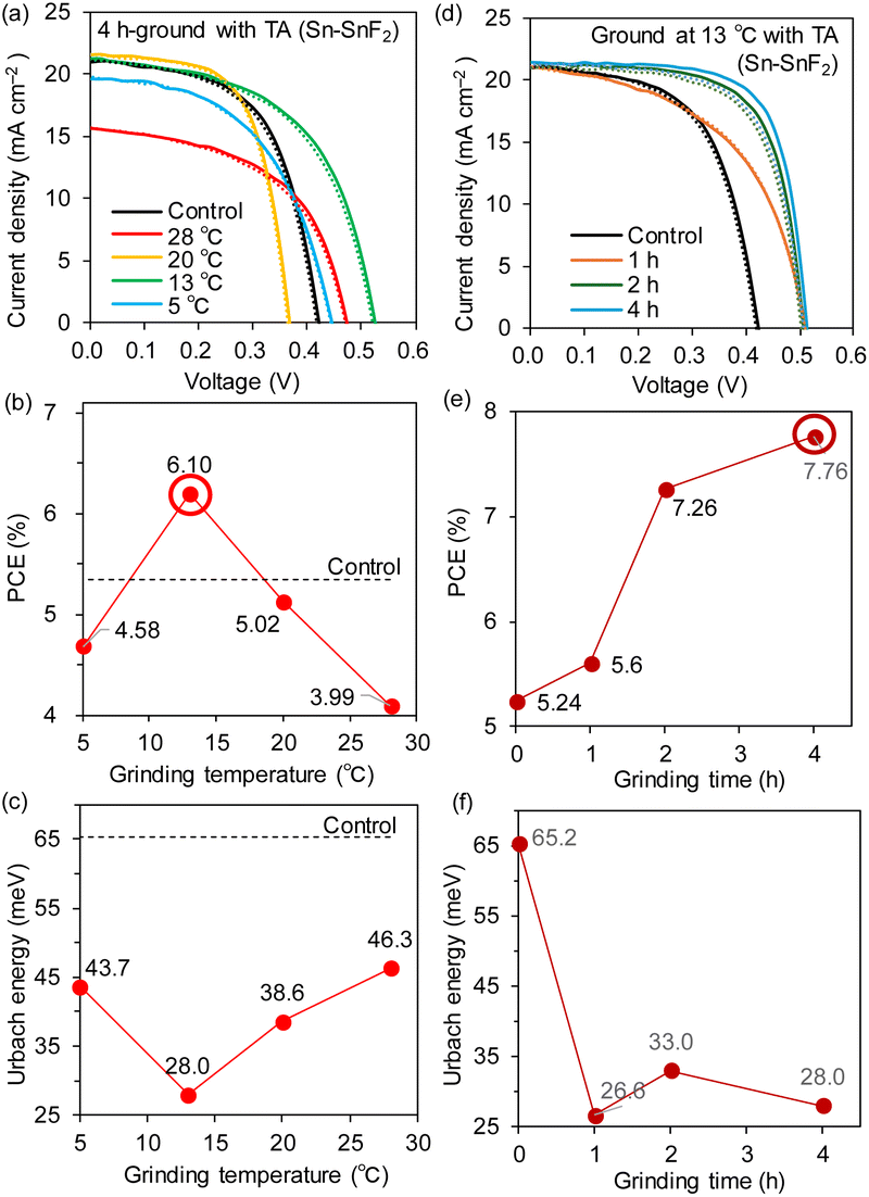 | ||
| Fig. 6 (a) JV curves, (b) PCE dependence, and (c) EU dependence on the grinding temperature. (d) JV curves, (e) PCE dependence, and (f) EU dependence on the grinding time at 13 °C. The solid and dotted lines in (a) and (d) represent forward and reverse scans, respectively. | ||
| Grinding T (°C) | Grinding time (h) | PCE (%) | V OC (V) | J SC (mA cm−2) | FF | HIb |
|---|---|---|---|---|---|---|
| a ITO/PEDOT: PSS/Sn perovskite/C60/BCP/Ag. The values in parentheses are the average and standard deviation for devices 12–38. The average values were calculated for forward and reverse scans using multiple devices. b Hysteresis index (HI) = (reverse PCE − forward PCE)/(forward PCE). c Control indicates no grinding. d Identical conditions but prepared in a different period. | ||||||
| Controlc | Controlc | 5.24 (4.45 ± 0.33) | 0.455 (0.406 ± 0.030) | 21.8 (20.818 ± 0.696) | 0.590 (0.528 ± 0.039) | 0.0000 (−0.0223 ± 0.0180) |
| 28 | 4 | 3.99 (3.47 ± 0.25) | 0.474 (0.440 ± 0.026) | 19.9 (17.0 ± 1.8) | 0.589 (0.471 ± 0.059) | −0.0183 (−0.0285 ± 0.0331) |
| 20 | 4 | 5.02 (4.65 ± 0.20) | 0.374 (0.359 ± 0.008) | 21.6 (21.1 ± 0.3) | 0.649 (0.614 ± 0.022) | 0.0007 (−0.0138 ± 0.0162) |
| 13d | 4d | 6.10 (5.18 ± 0.54) | 0.525 (0.487 ± 0.019) | 21.2 (20.5 ± 0.5) | 0.601 (0.518 ± 0.042) | 0.0029 (−0.0253 ± 0.0216) |
| 5 | 4 | 4.58 (3.70 ± 0.45) | 0.468 (0.399 ± 0.033) | 20.7 (19.4 ± 0.7) | 0.522 (0.476 ± 0.025) | −0.0005 (−0.0074 ± 0.0102) |
| 13 | 1 | 5.60 (4.13 ± 0.80) | 0.533 (0.471 ± 0.039) | 21.8 (19.1 ± 2.1) | 0.548 (0.456 ± 0.047) | 0.0006 (−0.0315 ± 0.0493) |
| 13 | 2 | 7.26 (5.59 ± 1.22) | 0.508 (0.476 ± 0.031) | 22.5 (21.3 ± 1.3) | 0.671 (0.547 ± 0.086) | −0.0066 (−0.0617 ± 0.0631) |
| 13d | 4d | 7.76 (5.60 ± 0.95) | 0.525 (0.472 ± 0.030) | 22.7 (21.4 ± 0.8) | 0.705 (0.552 ± 0.064) | 0.0029 (−0.0677 ± 0.0471) |
The XRD patterns of the ground Sn–SnF2 powder exhibited a superposition of the patterns of Sn and SnF2 without any new peaks or any differences among the temperatures examined (Fig. S16 (ESI†)). The Sn perovskite films processed with ground Sn–SnF2 exhibited strong XRD peaks at 13.9 and 28.0°, assigned to the (100) and (200) indices, respectively, also without any significant temperature dependence (Fig. S17 (ESI†)). The PA spectra and the bandgap energies (1.42–1.43 eV) were also independent of the grinding temperature (Fig. S18 (ESI†)); however, the EU displayed a clear and reasonable dependence on the temperature (Fig. 6c). Notably, the lowest EU (28 meV) was obtained for the maximum PCE at a grinding temperature of 13 °C.
Based on the analysis of temperature dependence, we again sought to optimize the grinding time at a fixed temperature of 13 °C. As displayed in Fig. 6d (JV curves) and 6e (PCE vs. grinding time), the PCE continuously increased with the grinding time and reached a maximum of 7.76% after 4 h of grinding. As listed in Table 1, the improvement in PCE is ascribed to the increase in VOC (0.455 to 0.525 V) along with the FF (0.590 to 0.705), whereas the JSC values (21.8 to 22.7 mA cm−2) and EQE spectra (Fig. S19 (ESI†)) remained unchanged.
The XRD patterns of the Sn–SnF2 powder ground at 13 °C for 1–4 h and the Sn perovskite films processed with this powder are shown in Fig. S20 and S21 (ESI†), respectively. No obvious differences were observed in the patterns, similar to previous results (Fig. S16 and S17 (ESI†)). However, the EU values decreased considerably from 65.2 meV for the control to 22.6–33.0 meV after 1–4 h of grinding (Fig. 6f). Although the EU and bandgap energy (Fig. S22 (ESI†)) did not precisely correlate with the device performance, a low EU represents a decrease in the trap state at the band edge, which improves the charge transport and decreases the VOC loss through reduced trap-assisted recombination.
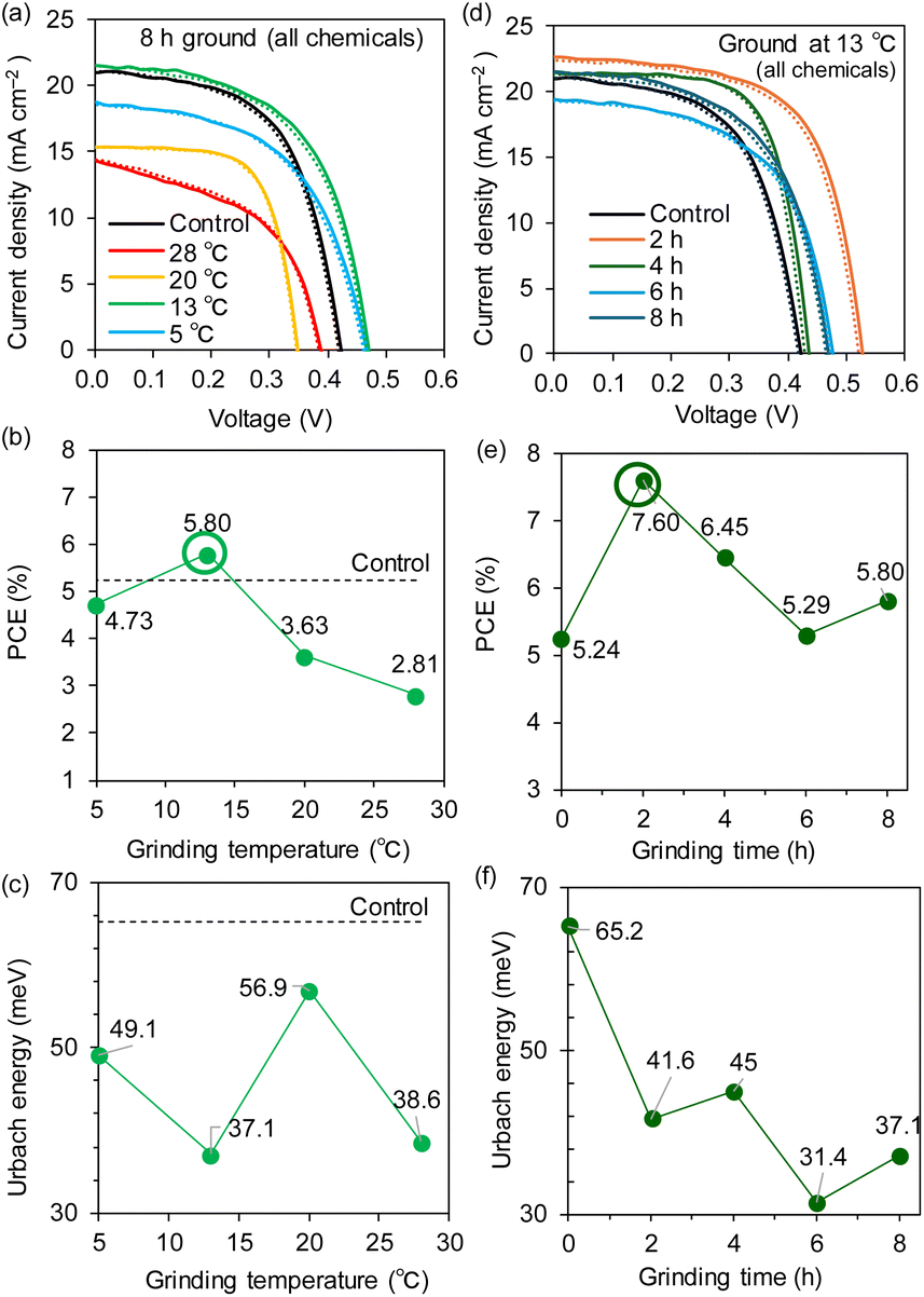
In the same way, we examined the dependence of the grinding temperature of the all-chemical ground system without TA processing for a fixed grinding time of 8 h. Notably, the optimal temperature for this system was also 13 °C, as is evident from the JV curves (Fig. 7a) and the PCE plot vs. the grinding temperature (Fig. 7b). The highest PCE of 5.80% was observed at 13 °C, whereas the PCE values significantly decreased to 3.63% at 20 °C and 2.81% at 28 °C (device parameters in Table 2 and EQE spectra in Fig. S23 (ESI†)). The XRD measurements of the all-chemical ground powders (Fig. S24 (ESI†)) and their Sn perovskite films (Fig. S25 (ESI†)) revealed that the intensity of the (100) peak reached its maximum at 13 °C among the temperatures examined. Moreover, as shown in Fig. 7c, the EU was minimized at 13 °C (37.1 meV) for the maximum PCE. The bandgap energies underwent a stepwise increase from 1.43 eV for 5–13 °C to 1.47–1.53 eV for 20–28 °C (Fig. S26 (ESI†)). These results are consistent with the device performance and indicate the particular weakness of Sn perovskites at high temperatures.
 | ||
| Fig. 7 (a) JV curves, (b) PCE dependence, and (c) EU dependence on the grinding temperature. (d) JV curves, (e) PCE dependence, and (f) EU dependence on the grinding time at 13 °C. The solid and dotted lines in (a) and (d) are forward and reverse scans, respectively. | ||
| Grinding T (°C) | Grinding time (h) | PCE (%) | V OC (V) | J SC (mA cm−2) | FF | HIb |
|---|---|---|---|---|---|---|
| a ITO/PEDOT: PSS/Sn perovskite/C60/BCP/Ag. The values in parentheses are the averages and standard deviations for devices 12–28. The average values were calculated for forward and reverse scans using multiple devices. b Hysteresis index (HI) = (reverse PCE − forward PCE)/(forward PCE). c Control indicates no grinding. d Identical data. | ||||||
| Controlc | Controlc | 5.24 (4.45 ± 0.33) | 0.455 (0.406 ± 0.030) | 21.8 (20.8 ± 0.7) | 0.590 (0.528 ± 0.039) | 0.0000 (−0.223 ± 0.0180) |
| 28 | 8 | 2.81 (1.81 ± 0.42) | 0.411 (0.356 ± 0.030) | 17.2 (14.3 ± 1.7) | 0.510 (0.351 ± 0.057) | 0.0000 (−0.005 ± 0.0219) |
| 20 | 8 | 3.63 (2.23 ± 0.64) | 0.348 (0.298 ± 0.040) | 15.4 (14.6 ± 0.5) | 0.679 (0.504 ± 0.089) | −0.0100 (−0.0783 ± 0.0670) |
| 13d | 8d | 5.80 (4.63 ± 0.45) | 0.480 (0.447 ± 0.031) | 22.4 (19.3 ± 2.7) | 0.582 (0.541 ± 0.028) | −0.0042 (−0.0335 ± 0.0274) |
| 5 | 8 | 4.73 (3.73 ± 0.54) | 0.493 (0.429 ± 0.036) | 18.8 (17.9 ± 0.46) | 0.543 (0.483 ± 0.033) | 0.0014 (−0.0222 ± 0.0176) |
| 13 | 2 | 7.60 (5.57 ± 1.13) | 0.544 (0.487 ± 0.037) | 23.2 (21.7 ± 0.9) | 0.637 (0.523 ± 0.070) | −0.0133 (−0.0374 ± 0.0199) |
| 13 | 4 | 6.45 (5.46 ± 0.71) | 0.461 (0.429 ± 0.021) | 22.1 (21.2 ± 0.6) | 0.702 (0.589 ± 0.069) | −0.0007 (−0.0158 ± 0.0155) |
| 13 | 6 | 5.29 (3.87 ± 0.59) | 0.477 (0.383 ± 0.045) | 20.9 (19.6 ± 0.7) | 0.571 (0.505 ± 0.034) | −0.0053 (−0.0338 ± 0.0494) |
| 13d | 8d | 5.80 (4.63 ± 0.45) | 0.480 (0.447 ± 0.031) | 22.4 (19.3 ± 2.7) | 0.582 (0.541 ± 0.028) | −0.0042 (−0.0335 ± 0.0042) |
Accordingly, we varied the grinding time (2, 4, 6, and 8 hours) for the all-chemical system at an optimal temperature of 13 °C. The JV curves and PCE plots with respect to the grinding time (Fig. 7d and e), respectively, showed that the PCEs increased from 5.24% for the control (no grinding) to 7.60% after 2 h of grinding and then slowly decreased (e.g., 6.45% for 4 h). All of the PSC parameters are maximized after 2 h of grinding, namely, JSC = 23.2 mA cm−2, VOC = 0.544 V, and FF = 0.637 (Table 2 and Fig. S27 (ESI†) (EQE spectra)). The XRD patterns of the all-chemical ground powders (Fig. S28 (ESI†)) and the corresponding Sn perovskite (Fig. S29 (ESI†)) did not clearly correlate with the obtained PCE values. In contrast, the EU (Fig. 7f) and bandgap (Fig. S30 (ESI†)) decreased reasonably to 41.6 meV and 1.43 eV at 2 h, respectively. This optimal grinding time of 2 h at 13 °C is considerably shorter than the 8 h required for grinding at room temperature (Fig. 2b), which is beneficial for shortening the total device fabrication time. An improved tolerance to an accidentally increased O2 concentration (hundreds of ppm) in a glove box is another advantage of the ground samples (PCE = 0.06% for the control, 4.46% for ground Sn–SnF2, and 3.12% for all ground chemicals; see Fig. S31 (ESI) and Table S5 (ESI†)). The Sn perovskite films based on the Sn–SnF2 and all-chemical systems prepared at the optimized grinding temperature and time, exhibited pinhole-free densely packed multigrain features, as evidenced by the SEM images (Fig. 8a and b), which is consistent with their improved PCE values.
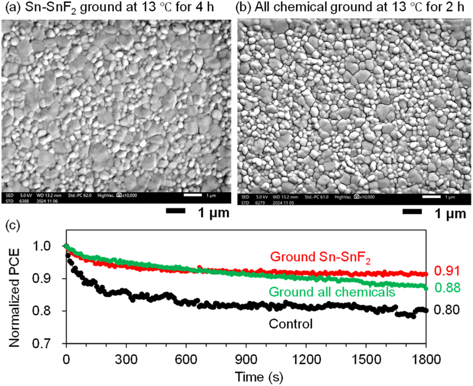 | ||
| Fig. 8 SEM images of PEA0.1FA0.9SnI3 processed with (a) Sn–SnF2 ground at 13 °C for 4 h followed by TA and (b) the all-chemical sample ground at 13 °C for 2 h. This grinding condition is optimal. (c) Normalized time-dependent PCEs (MPPT) of PEA0.1FA0.9SnI3 PSCs processed with the non-ground Sn–SnF2 system (control), ground Sn–SnF2, and ground all-chemical system. A continuous pseudo-sunlight was exposed. The initial PCEs were 5.92, 6.84, and 6.21%, respectively. See Table S7 (ESI†) for the other initial device parameters. | ||
X-ray photoelectron spectroscopy (XPS) measurements of the Sn perovskite films were performed for the control, ground Sn–SnF2, and ground all-chemical systems (Fig. S32 (ESI†)). The XPS peaks at 486 and 495 eV arising from the 3d orbital of Sn(II)29,42 were mostly similar among the samples. Energy-dispersive X-ray (EDX) spectroscopy of the ground powder showed signals from Sn and I with no signals from elements that may be included from the grinding ball and vessel (Fig. S33 (ESI†)). Electrochemical impedance spectroscopy (EIS) measurements of the Sn PSCs showed a marginal increase in the slope of Mott–Schottky plot46,58 from the control, all-chemical, to Sn–SnF2 systems (Fig. S34 (ESI†)). This suggests a decrease in the surface trap density in the ground-powder-processed Sn PSCs.
Discussion of the temperature effect
Our study revealed that low-temperature (13 °C) grinding of the precursors increased the PCE of PSCs fabricated with both the Sn–SnF2 and all-chemical systems; however excessively low (5 °C) and high (>20 °C) temperatures had a negative effect. For the Sn–SnF2 system, the PCE gradually increased with grinding time and was mostly saturated or slightly lower after 5 h. In contrast, the grinding time for the all-chemical system has a larger impact on the PCE than that of the Sn–SnF2 system; moreover, TA processing at 170 °C after grinding significantly lowered the device performance. We thus discuss the temperature effect on the basis of the following reaction enthalpies (ΔrH) at 298 K, all of which could contribute to the temperature changes during the grinding process, and were calculated from the enthalpy of formation of the species.59| Sn + SnI4 → 2SnI2, ΔrH (298 K) = −54.5 kcal mol−1 | (1) |
| Sn + I2 → SnI2, ΔrH (298 K) = −88.8 kcal mol−1 | (2) |
| SnI2 + I2 → SnI4, ΔrH (298 K) = −34.3 kcal mol−1 | (3) |
The reductive and oxidative formations of SnI2 from Sn metal (eqn (1) and (2), respectively) are largely exothermic; therefore, a low grinding temperature is preferred to lower the amounts of Sn4+ and I2. Untraceable amounts of Sn4+ are presumably included in the SnI2 precursors and generated during the film fabrication process, whereas I2 may be generated from the decomposition of organic salts. I2 can also react with SnI2 to form SnI4 according to eqn (3), whereas the presence of excess Sn at low temperatures gives rise to the main path of SnI2 formation viaeqn (2).30 In addition to the accelerated oxidation of Sn2+ in high-temperature DMSO solutions,52 these thermodynamics reasonably explain the preference for low-temperature grinding in the all-chemical systems. In contrast, the reason for the decline in the performance at the excessively low temperature (5 °C) is unknown. This may be due to the inclusion of a small amount of dewfall that appeared in the grinding vessel under a liquid nitrogen atmosphere, although the vessel was carefully sealed and opened in an N2-filled glove box. Notably, the temperature of the glove box during spin coating of the Sn perovskite films also has a critical effect on the performance, where the PCE (5.24%) of the control Sn-PSC (non-ground sample) prepared at 22 °C is higher than those of 3.73% at 19 °C, 4.79% at 24 °C, and 2.01% at 27 °C (Fig. S35 and Table S6 (ESI†)).
SnF2 is a reductant, and the chemical reactions involved in Sn perovskite processing are as follows:37
| 2SnF2 + SnI4 = SnF4 + 2SnI2, ΔE = 0.35 eV | (4) |
| 4SnF2 + SnI4 = Sn3F8 + 2SnI2, ΔE = −0.70 eV | (5) |
| 2SnF2 + SnF4 = Sn3F8, ΔE = −1.05 eV | (6) |
| 4SnF2 + I2 = Sn3F8 + SnI2, ΔE = −0.73 eV | (7) |
Although the formation of the perovskite from the all-chemical system provided clear evidence that the mechanochemical reaction actually took place, it was not clear whether the Sn–SnF2 system underwent any reactions. We performed 119Sn nuclear magnetic resonance (NMR) measurements of SnF2 and Sn–SnF2 (ground and filtered); however, Sn4+ and the reduction thereof36 were not detected in either solution (Fig. S36 (ESI†)). However, the acceleration of Sn4+ reduction was observed in the DMSO solution (Fig. 4), suggesting that SnF2-related reactions are presumably activated by grinding. The improved stability of the Sn PSC fabricated with the Sn–SnF2- and the all-chemical ground systems compared to the control (no grinding) was also notable (Fig. 8c, maximum power point tracking (MPPT) under continuous illumination with pseudo-sunlight for 30 min), reinforcing the advantage of our mechanochemical pretreatment of Sn perovskite precursors.
Conclusions
We investigated the mechanochemical grinding of Sn powder with SnF2 (the Sn–SnF2 system) for comparison with the combination of Sn perovskite precursors (the all-chemical system) in a ball-mill facility. The grinding temperature and time significantly affected the PCE values of the PEA0.1FA0.9SnI3 PSCs. For the Sn–SnF2 system, grinding at 13 °C for 4 h was optimal, and increased the PCE to 7.76% with JSC = 22.7 mA cm−2, VOC = 0.525 V, and FF = 0.705. For the all-chemical system, the optimal conditions were 13 °C for 2 h to yield a PCE of 7.60% with JSC = 23.2 mA cm−2, VOC = 0.544 V, and FF = 0.637. The minimized EU and bandgap energies along with the improved multicrystalline morphology under optimal conditions, rationalized the improved PCE, whereas the XRD patterns of the ground powder and Sn perovskite films did not differ to any noticeable extent. More importantly, the exothermic reaction involving the elimination of Sn4+ supports the preference for low-temperature processes. In addition, the accelerated reduction of SnI4 in DMSO and the oxygen tolerance of the Sn-PSCs demonstrated the advantages of grinding the precursors. Our work led to the development of a reliable and reproducible method to fabricate Sn PSCs and offers a thermodynamics-based strategy toward efficient lead-free PSCs.Experimental
Materials
Chemicals for the synthesis of passivation molecules were purchased from Sigma-Aldrich or Tokyo Chemical Co. Ltd (TCI). Solvents for the synthesis were purchased from Kishida Kagaku Co. Ltd, Kanto Kagaku Co. Ltd, or Wako-Fuji Film Industries Ltd (WFFI) and used as received. Deoxidized grade dimethyl sulfoxide (DMSO) and toluene were purchased form WFFI and used as received. Formamidinium iodide (FAI) and phenethylammonium iodide (PEAI) were purchased from GreatCell Solar (Australia). BCP (bathocuproine purified by sublimation, 99.0%) were purchased from Tokyo Chemical Industry Co. Ltd. SnF2 (99%), and Sn powder (<1 ppm, H2O < 0.001%) were purchased from Wako-Fuji Film Industries Ltd. SnI2 (anhydrous, beads, 99.99% trace metals basis) were purchased from Sigma-Aldrich. They were used without further purification.Mechanochemical pretreatment of powder
For the Sn–SnF2 system, 500 mg of the mixture (250 mg Sn powder and 250 mg SnF2 powder) was weighed, placed in a grinding stainless vessel (volume: 5 mL) with φ = 7 mm two stainless balls, and sealed in a glovebox. For the all-chemical system, a total weight of 4225.2 mg chemicals (PEAI: 119.4 mg, FAI: 742.8 mg, SnI2: 1788 mg, SnF2: 75 mg, Sn: 1500 mg) was weighed in a glove box and sealed similarly into a vessel. The ball milling process was carried out using a Retsch MM400 model at 30 Hz in a hand-made cooling box (5–28 °C) with ±0.5 °C accuracy as shown in Fig. S1 (ESI†). After grinding was complete, the vessels containing the ground mix powder were transferred to a glovebox, followed (or not) by thermal annealing at 170 °C for one hour.Precursor preparation
A 0.8 M DMSO solution of PEA0.1FA0.9SnI3 with 10 mol% SnF2 and 250 mg mL−1 Sn powder was applied throughout the whole study. For the ground Sn–SnF2 system, 19.9 mg of PEAI, 123.8 mg of FAI, 298.0 mg of SnI2, 25 mg of ground Sn–SnF2 powder, and 237.5 mg of Sn powder were weighed and poured into 1 mL of DMSO and rigorously stirred at 45 °C for more than 2 h in a glove box. For a ground all-chemical system, 704.2 mg of ground mixed powder of all chemicals was weighed and poured into 1 mL of DMSO and rigorously stirred at 45 °C for more than 2 h in a glovebox.Device fabrication and characterization
Under ambient conditions, a PEDOT: PSS layer (Clevios P VP AI 4083) was deposited on a cleaned Sn-doped ITO (155 nm in thickness, 2.5 × 2.5 cm2 in size, and ∼90% transmittance at 550 nm, <10 Ω sq−1) on glass by spin-coating at the slope of 5 s, 5000 rpm for 60 s, and a slope of 1 s followed by thermal annealing at 140 °C for 20 min. In a glovebox (the internal temperature was controlled using a radiator attached to a chiller), the precursor solution just after filtering Sn powder off was dropped on PEDOT: PSS/ITO and spun at a slope of 5 s, 5000 rpm for 60 s, and a slope of 1 s. At a total elapsed time of 63 s, 450 μL of toluene warmed at 65 °C prior to the use (HAT method) was continuously dropped within 1 s by using an φ = ∼2 mm dry pipette tip at appropriate position. A transparent brownish film was thermally annealed on a hot plate at 45, 65, and 100 °C for each 10 min, which led to a gradual colour change to a deeper colour. The films were transferred to a vacuum vessel (<10−4 Pa), and a 30 nm-thick C60 layer was thermally deposited at ∼0.1 Å s−1 (<5 nm) and ∼0.2 Å s−1 (>5 nm). After replacing with a nine-dot blank mask, 7 nm-thick BCP at ∼0.1 Å s−1 and 100 nm-thick Ag layers at ∼0.1 Å s−1 (<3 nm), ∼0.2 Å s−1 (3–20 nm) and ∼0.5 Å s−1 (>20 nm) were sequentially deposited in a vacuum chamber. The current density–voltage curves were measured using a source meter unit (SMU) (ADCMT Corp., 6241A) under AM1.5G pseudo-solar illumination at 100 mW cm−2 using a 300 W solar simulator (SAN-EI, XES-301S, monitored by a calibrated standard cell of Bunko Keiki BS-520BK). The device was packed in a measurement chamber with a light mask (area = 0.0314 cm2 and the area of the device = 0.071 cm2). The scan was conducted from 0.7 V to −0.1 V and then backwards, with a step size of 0.02 V, a hold time of 150 ms, a limited current of 20 mA, an integration time of 10 ms, and a measurement delay of 100 ms. The EQE spectra were recorded using a Bunko Keiki SM-250KD equipped with a Keithley 2401 SMU. The monochromatic light power of the EQE instrument was calibrated using a silicon photovoltaic cell (Bunko Keiki model S1337-1010BQ). All the measurements were performed at 25 °C in the air.Measurements
Steady-state photoabsorption and photoluminescence spectroscopy studies were performed using Jasco V-730 ultraviolet-visible (UV-vis) and Jasco FP-8300 spectrophotometers, respectively. X-ray diffraction (XRD) measurements were performed using a Rigaku Corp. MiniFlex-600 instrument (Cu Kα radiation: λ = 1.54 Å). SEM measurements were performed on a JEOL JSM-IT700HR (5 keV, 50 μA). Photoluminescence lifetime measurements based on a time-correlated single-photon counting (TCSPC) technique for TRPL were performed on a HORIBA model FluoroCube 3000U-UltraFast-SP spectrophotometer (λex = 377 nm, resolution <50 ps). In the TRPL measurements, samples were prepared as quartz/polystyrene sulfonate (PSS)/Sn perovskite/polymethylmethacrylate (PMAA) to prevent hole transfer to PEDOT: PSS and degradation in the air. 119Sn NMR was performed on an Oxford Instruments X-pulse (60 MHz, a table top NMR with a permanent magnet). XPS and EDX measurements were performed using a Shimadzu KRATOS ULTRA2 and a Malvern-Panalytical Epsilon 1, respectively. EIS measurements were conducted on a HIOKI IM3570.Data availability
The data supporting this article have been included as part of the ESI.†Conflicts of interest
The authors declare no competing financial interests.Acknowledgements
We acknowledge the financial support received from the Japan Science and Technology Agency (JST) CREST (JPMJCR23O2 to A. S.), MIRAI (JPMJMI22E2 to A. W. and A. S.), and PRESTO (JPMJPR21A2 to I. F.), the New Energy and Industrial Technology Development Organization (NEDO) Green Innovation Project (JP21578854 to A. S.), and KAKENHI of the Japan Society for the Promotion of Science (JSPS) (JP20H05836 and JP24H00484 to A. S.). This research was partially supported by the Research Support Project for Life Science and Drug Discovery (Basis for Supporting Innovative Drug Discovery and Life Science Research (BINDS)) from AMED under Grant number JP24AMA121054. The authors thank Mr Hitoshi Haneoka at the Comprehensive Analysis Center, SANKEN, Osaka University, for assistance with XPS measurements, Mr Shogo Tadokoro at Osaka University for the operation of device stability measurements and Ms. Mayumi Asano at JASCO International for the 119Sn NMR measurements.Notes and references
- P. Zhu, C. Chen, J. Dai, Y. Zhang, R. Mao, S. Chen, J. Huang and J. Zhu, Adv. Mater., 2024, 36, 2307357 CrossRef CAS.
- H.-S. Kim and N.-G. Park, Adv. Energy Mater., 2024, 14, 2400089 Search PubMed.
- A. Kojima, K. Teshima, Y. Shirai and T. Miyasaka, J. Am. Chem. Soc., 2009, 131, 6050–6051 CrossRef CAS PubMed.
- H.-S. Kim, C.-R. Lee, J.-H. Im, K.-B. Lee, T. Moehl, A. Marchioro, S.-J. Moon, R. Humphry-Baker, J.-H. Yum, J. E. Moser, M. Grätzel and N.-G. Park, Sci. Rep., 2012, 2, 591 CrossRef PubMed.
- M. M. Lee, J. Teuscher, T. Miyasaka, T. N. Murakami and H. J. Snaith, Science, 2012, 338, 643–647 CrossRef CAS PubMed.
- G. Xing, N. Mathews, S. Sun, S. S. Lim, Y. M. Lam, M. Grätzel, S. Mhaisalkar and T. C. Sum, Science, 2013, 342, 344–347 CrossRef CAS PubMed.
- S. Li, Y. Jiang, J. Xu, D. Wang, Z. Ding, T. Zhu, B. Chen, Y. Yang, M. Wei, R. Guo, Y. Hou, Y. Chen, C. Sun, K. Wei, S. M. H. Qaid, H. Lu, H. Tan, D. Di, J. Chen, M. Grätzel, E. H. Sargent and M. Yuan, Nature, 2024, 635, 82–88 CrossRef CAS PubMed.
- Z. Liang, Y. Zhang, H. Xu, W. Chen, B. Liu, J. Zhang, H. Zhang, Z. Wang, D.-H. Kang, J. Zeng, X. Gao, Q. Wang, H. Hu, H. Zhou, X. Cai, X. Tian, P. Reiss, B. Xu, T. Kirchartz, Z. Xiao, S. Dai, N.-G. Park, J. Ye and X. Pan, Nature, 2023, 624, 557–563 CrossRef.
- H. Gao, R. Lin, S. Zhao, W. Wang, S. Dayneko, C. Duan, C. Ji, H. Sun, A. D. Bui, C. Liu, J. Wen, W. Kong, H. Luo, X. Zheng, Z. Liu, H. Nguyen, J. Xie, L. Li, M. I. Saidaminov and H. Tan, Science, 2024, 383, 855–859 CrossRef CAS PubMed.
- Y. Huang, K. Yan, X. Wang, B. Li, B. Niu, M. Yan, Z. Shen, K. Zhou, Y. Fang, X. Yu, H. Chen, L. Zhang and C.-Z. Li, Adv. Mater., 2024, 36, 2408101 CrossRef CAS.
- W. Ke and M. G. Kanatzidis, Nat. Commun., 2019, 10, 965 CrossRef PubMed.
- E. Jokar, C.-H. Chien, C.-M. Tsai, A. Fathi and E. W.-G. Diau, Adv. Mater., 2019, 31, 1804835 CrossRef PubMed.
- S. Attique, N. Ali, S. Ali, R. Khatoon, N. Li, A. Khesro, S. Rauf, S. Yang and H. Wu, Adv. Sci., 2020, 7, 201903143 Search PubMed.
- R. Chiara, M. Morana and L. Malavasi, ChemPlusChem, 2021, 86, 879–888 CrossRef CAS.
- Y.-F. Chen, Z.-M. Luo, C.-H. Chiang and C.-G. Wu, ACS Appl. Mater. Interfaces, 2022, 14, 46603–46614 CrossRef CAS.
- F. Iyoda, R. Nishikubo, A. Wakamiya and A. Saeki, ACS Appl. Energy Mater., 2020, 3, 8224–8232 CrossRef CAS.
- C. Nishikawa, R. Nishikubo, F. Ishiwari and A. Saeki, JACS Au, 2023, 3, 3194–3203 CrossRef CAS.
- W. Ke, C. C. Stoumpos and M. G. Kanatzidis, Adv. Mater., 2019, 31, 1803230 CrossRef CAS.
- G. Nasti and A. Abate, Adv. Energy Mater., 2019, 9, 1902467 Search PubMed.
- R. Nishikubo, N. Ishida, Y. Katsuki, A. Wakamiya and A. Saeki, J. Phys. Chem. C, 2017, 121, 19650–19656 CrossRef CAS.
- E. Nakanishi, R. Nishikubo, F. Ishiwari, T. Nakamura, A. Wakamiya and A. Saeki, ACS Mater. Lett., 2022, 4, 1124–1131 CrossRef CAS.
- W. Shockley and H. J. Queisser, J. Appl. Phys., 1961, 32, 510–519 CrossRef CAS.
- C. C. Stoumpos, C. D. Malliakas and M. G. Kanatzidis, Inorg. Chem., 2013, 52, 9019–9038 CrossRef CAS.
- J. Chen, J. Luo, E. Hou, P. Song, Y. Li, C. Sun, W. Feng, S. Cheng, H. Zhang, L. Xie, C. Tianm and Z. Wei, Nat. Photonics, 2024, 18, 464–470 CrossRef CAS.
- P. F. Chan, M. Qin, C.-J. Su, L. Ye, X. Wang, Y. Wang, X. Guan, Z. Lu, G. Li, T. Ngai, S. W. Tsang, N. Zhao and X. Lu, Adv. Sci., 2024, 11, 2309668 CrossRef CAS PubMed.
- J. Choi, S. J. Yang, G. S. Han, W. Sung, D. Yoo and K. Cho, Chem. Mater., 2023, 35, 1148–1158 CrossRef CAS.
- L. Wang, Q. Miao, D. Wang, M. Chen, H. Bi, J. Liu, A. K. Baranwal, G. Kapil, Y. Sanehira, T. Kitamura, T. Ma, Z. Zhang, Q. Shen and S. Hayase, Angew. Chem., Int. Ed., 2023, 62, e202307228 CrossRef CAS PubMed.
- L. Wang, M. Chen, S. Yang, N. Uezono, Q. Miao, G. Kapil, A. K. Baranwal, Y. Sanehira, D. Wang, D. Liu, T. Ma, K. Ozawa, T. Sakurai, Z. Zhang, Q. Shen and S. Hayase, ACS Energy Lett., 2022, 7, 3703–3708 CrossRef CAS.
- B.-B. Yu, Z. Chen, Y. Zhu, Y. Wang, B. Han, G. Chen, X. Zhang, Z. Du and Z. He, Adv. Mater., 2021, 33, 2102055 CrossRef CAS.
- X. Jiang, H. Li, Q. Zhou, M. Wei, L. Jiang, Z. Wang, Z. Peng, F. Wang, Z. Zang, K. Xu, Y. Hou, S. Teale, W. Zhou, R. Si, X. Gao, E. H. Sargent and Z. Ning, J. Am. Chem. Soc., 2021, 143, 10970–10976 CrossRef CAS PubMed.
- J. Zillner, H.-G. Boyen, P. Schulz, J. Hanisch, N. Gauquelin, J. Verbeeck, J. Küffner, D. Desta, L. Eisele, E. Ahlswede and M. Powalla, Adv. Funct. Mater., 2022, 32, 2109649 CrossRef CAS.
- S. Gupta, T. Bendikov, G. Hodes and D. Cahen, ACS Energy Lett., 2016, 1, 1028–1033 CrossRef CAS.
- X. Wan, C. Xu, H. Wang, Z. Jiang, F. Li, G. Xu, Z. Dai, X. He and Q. Song, Small, 2024, 20, 2401136 CrossRef CAS.
- M. H. Kumar, S. Dharani, W. L. Leong, P. P. Boix, R. R. Prabhakar, T. Baikie, C. Shi, H. Ding, R. Ramesh, M. Asta, M. Graetzel, S. G. Mhaisalkar and N. Mathews, Adv. Mater., 2014, 26, 7122–7127 CrossRef CAS PubMed.
- W. Liao, D. Zhao, Y. Yu, C. R. Grice, C. Wang, A. J. Cimaroli, P. Schulz, W. Meng, K. Zhu, R.-G. Xiong and Y. Yan, Adv. Mater., 2016, 28, 9333–9340 CrossRef CAS PubMed.
- J. Pascual, M. Flatken, R. Félix, G. Li, S. Turren-Cruz, M. H. Aldamasy, C. Hartmann, M. Li, D. Di Girolamo, G. Nasti, E. Hgsam, R. G. Wilks, A. Dallmann, M. Bär, A. Hoell and A. Abate, Angew. Chem., Int. Ed., 2021, 60, 21583–21591 CrossRef CAS PubMed.
- D. Meggiolaro, L. Gregori and F. D. Angelis, ACS Energy Lett., 2023, 8, 2373–2375 CrossRef CAS.
- F. Gu, S. Ye, Z. Zhao, H. Rao, Z. Liu, Z. Bian and C. Huang, Sol. RRL, 2018, 2, 1800136 CrossRef.
- E. Nakanishi, R. Nishikubo, A. Wakamiya and A. Saeki, J. Phys. Chem. Lett., 2020, 11, 4043–4051 CrossRef CAS.
- J. Chen, C. Wu, M. Wang, Y. Shen, J. Qian, W. Shen, K. Cao and S. Chen, ACS Appl. Energy Mater., 2023, 6, 9815–9823 CrossRef CAS.
- B. Dou, L. M. Wheeler, J. A. Christians, D. T. Moore, S. P. Harvey, J. J. Berry, F. S. Barnes, S. E. Shaheen and M. F. A. M. van Hest, ACS Energy Lett., 2018, 3, 979–985 CrossRef CAS.
- T. Nakamura, S. Yakumaru, M. A. Truong, K. Kim, J. Liu, S. Hu, K. Otsuka, R. Hashimoto, R. Murdey, T. Sasamori, H. D. Kim, H. Ohkita, T. Handa, Y. Kanemitsu and A. Wakamiya, Nat. Commun., 2020, 11, 3008 CrossRef CAS PubMed.
- S. L. James, C. J. Adams, C. Bolm, D. Braga, P. Collier, T. Friscic, F. Grepioni, K. D. M. Harris, G. Hyett, W. Jones, A. Krebs, J. Mack, L. Maini, A. G. Orpen, I. P. Parkin, W. C. Shearouse, J. W. Steed and D. C. Waddell, Chem. Soc. Rev., 2012, 41, 413–447 RSC.
- K. Kubota and H. Ito, Trends Chem., 2020, 2, 1066–1081 Search PubMed.
- A. M. Elseman, M. M. Rashad and A. M. Hassan, ACS Sustainable Chem. Eng., 2016, 4, 4875–4886 CrossRef CAS.
- D. Prochowicz, P. Yadav, M. Saliba, M. Saski, S. M. Zakeeruddin, J. Lewiński and M. Grätzel, ACS Appl. Mater. Interfaces, 2017, 9, 28418–28425 CrossRef CAS.
- N. Leupold, K. Schötz, S. Cacovich, I. Bauer, M. Schultz, M. Daubinger, L. Kaiser, A. Rebai, J. Rousset, A. Köhler, P. Schulz, R. Moos and F. Panzer, ACS Appl. Mater. Interfaces, 2019, 11, 30259–30268 CrossRef CAS.
- M. Saski, D. Prochowicz, W. Marynowski and J. Lewiński, Eur. J. Inorg. Chem., 2019, 22, 2680–2684 CrossRef.
- D. J. Kubicki, D. Prochowicz, E. Salager, A. Rakhmatullin, C. P. Grey, L. Emsley and S. D. Stranks, J. Am. Chem. Soc., 2020, 142, 7813–7826 CrossRef CAS PubMed.
- C. A. López, C. Abia, J. Gainza, P. Kayser, N. N. Nemes, O. J. Dura, J. L. Martínez, M. T. Fernández-Díaz, C. Álvarez-Galván and J. A. Alonso, Mater. Adv., 2021, 2, 3620–3628 RSC.
- H. Cho, Y. Yun, W. C. Choi, I. S. Cho and S. Lee, Ceramics Int., 2022, 48, 3368–3373 CrossRef CAS.
- J. Pascual, G. Nasti, M. H. Aldamasy, J. A. Smith, M. Flatken, N. Phung, D. D. Girolamo, S.-H. LiM. Turren-Cruz, A. Dallmann, R. Avolio and A. Abate, Mater. Adv., 2020, 1, 1066–1070 RSC.
- J. Liu, M. Ozaki, S. Yakumaru, T. Handa, R. Nishikubo, Y. Kanemitsu, A. Saeki, Y. Murata, R. Murdey and A. Wakamiya, Angew. Chem., Int. Ed., 2018, 57, 13221–13225 CrossRef CAS PubMed.
- Y. Dang, Y. Zhou, X. Liu, D. Ju, S. Xia, H. Xia and X. Tao, Angew. Chem., Int. Ed., 2016, 55, 3447–3450 CrossRef CAS.
- A. F. Akbulatov, S. A. Tsarev, M. Elshobaki, S. Y. Luchkin, I. S. Zhidkov, E. Z. Kurmaev, S. M. Aldoshin, K. J. Stevenson and P. A. Troshin, J. Phys. Chem. C, 2019, 123, 26862–26869 CrossRef CAS.
- Z. Zhu, C. –C. Chueh, N. Li, C. Mao and A. K.-Y. Jen, Adv. Mater., 2018, 30, 1703800 CrossRef.
- S. Kahmann, O. Nazarenko, S. Shao, O. Hordiichuk, M. Kepenekian, J. Even, M. V. Kovalenko, G. R. Blake and M. A. Loi, ACS Energy Lett., 2020, 5, 2512–2519 CrossRef CAS.
- O. Almora, C. Aranda, E. Mas-Marzá and G. Garcia-Belmonte, Appl. Phys. Lett., 2016, 109, 173903 CrossRef.
- R. E. Pabst, D. L. Perry, J. L. Margrave and J. L. Franklin, Int. J. Mass Spectrometry Ion Phys., 1977, 24, 323–333 CrossRef CAS.
Footnote |
| † Electronic supplementary information (ESI) available: Previous reports of Sn-PSCs (Table S1); device parameters (Tables S2 and S3); TRPL parameters (Table S4); effects of high O2 concentration (Table S5) and temperature (Table S6) in a glovebox; initial PV parameters for MPPT (Table S7); ball mill facility, JV curves, Tauc plot, EQE, XRD, photoabsorption spectra, SEM images, XPS, EDX, EIS, NMR, and still pictures of ground powder (Fig. S1–S36); (PDF). See DOI: https://doi.org/10.1039/d4el00034j |
| This journal is © The Royal Society of Chemistry 2025 |