 Open Access Article
Creative Commons Attribution 3.0 Unported Licence
Directing SEI formation on Si-based electrodes using atomic layer deposition†
Supti
Das
a,
Anders
Brennhagen
a,
Carmen
Cavallo‡
a,
Veronica Anne-Line Kathrine
Killi
a,
Ingvild Julie Thue
Jensen
b,
Annett
Thøgersen
b,
Jan Petter
Mæhlen
c,
Samson Yuxiu
Lai
 c,
Ola
Nilsen
 a and
Alexey Y.
Koposov
 *ac
*ac
aCentre for Materials Science and Nanotechnology, Department of Chemistry, University of Oslo, PO Box 1033, Blindern, 0315, Oslo, Norway. E-mail: alexey.koposov@kjemi.uio.no
bSINTEF Industry, Materials Physics, Forskningsveien 1, 0373 Oslo, Norway
cDepartment of Battery Technology, Institute for Energy Technology (IFE), Instituttveien 18, 2007, Kjeller, Norway
First published on 21st November 2024
Abstract
The design of artificial solid eletroctrolyte interphase is an important task to minimize capacity losses in Li-ion batteries. Herein, TiO2 created through atomic layer deposition was used as an artificial SEI on Si nanoparticles. Such coating led to substantial improvement of cycling stability when evaluated with FEC-free electrolyte.
Since the commercialization of Li-ion batteries (LIBs) by Sony in early 1990s,1 it has been one of the most predominant energy storage solutions for a wide variety of applications such as electric vehicles, grid storage, and multiple portable electronic devices.2–5 However, the energy density of modern LIBs is not adequate to completely satisfy the growing demand for energy storage. Therefore, there is a necessity for low-cost LIBs that can safely deliver high power and energy density with a long cycle life. This need drives the global search for new active materials and electrolytes to replace those that are currently utilized in commercially produced LIBs. Within this search, the quest for suitable high-capacity negative electrodes for high-performance LIBs has led to the investigation of various materials that can outperform state-of-the-art graphite with a capacity of 372 mA h g−1.6 Considerable interest has been devoted to alloying-type anode materials, as they can accommodate multiple Li-ions per alloying atom.7
Among these alloying materials, silicon (Si) has gained a great traction attributed to its low working potential, light weight, high abundance and theoretical capacity almost ten times higher (3579 mA h g−1) than that of graphite.8–10 However, the grand challenge of developing Si-based anodes is to mitigate the massive volume changes (∼300%) during Li-ion insertion (lithiation) and extraction (delithiation) processes, which lead to severe capacity decay during continuous cycling. This most intractable problem causes pulverization of Si resulting in loss of electrical connection within the electrodes, and a continuous growth of the solid electrolyte interphase (SEI) layer due to the constant changes of the Si surface area. As a result, these anode materials typically show inferior cycling stability and low initial Coulombic efficiency. Moreover, the continuously growing SEI constantly consumes the electrolyte components, which ultimately results in cell failure.11 In addition, aggregation of Si particles through electrochemical sintering results in poor kinetics of the electrodes.12 These limitations hold back the potential application of Si-based anodes for efficient, long lasting, and safe LIBs.
The design of stable SEI on Si-based electrodes represents one of the possible routes for improving their cyclability.13–15 The common strategy for this task is to use electrolyte additives, e.g. fluoroethylene carbonate (FEC) which promotes formation of relatively stable SEI.16,17 However, additives such as FEC are continuously consumed during electrochemical cycling, and their enhancing effect disappears when their reservoir in the electrolyte is depleted.18 In addition, electrolyte additives add weight and cost to a battery.
Alternative strategies such as surface coating and hybridization with carbon-based materials have been shown to improve cyclability. Particularly, employing a suitable surface coating on nanostructured Si has been observed to improve cycling performance by reducing the reactivity of Si with electrolytes, although the challenge with huge volume changes cannot be eradicated entirely.19
Among multiple coating techniques, atomic layer deposition (ALD) has been demonstrated to be a very versatile method for interfacial engineering. Unlike other thin film deposition methods (e.g. PVD, CVD), ALD enables an excellent control over the uniformity, conformality and thickness of thin films at the atomic level due to its surface-controlled nature. In addition, ALD could be used for modification of particles and is not limited to only flat film surfaces. Such coating could be used to enhance the battery performance by providing an artificial SEI layer preventing detrimental side reactions at the electrolyte/electrode interface.20 Several types of ALD coating have been explored for their use in modification of battery materials, such as transition metal oxides (Al2O3, TiO2, ZrO2, ZnO and SiO2), metal nitride (TiN) and aluminum oxynitride (AlOxNy).19,21–25 Among these, TiO2 has been proven as one of the most promising coating materials to enhance the cycle life and rate capability of Si-based electrodes due to its small volume change during cycling (<4%), structural stability, low polarization and good electrochemical reversibility.25–27 In this study we coated Si nanoparticles with TiO2 using ALD to examine the influence of the coating on electrochemical performance in LIBs.
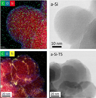
The pristine nanoparticles of amorphous Si (a-Si) with a diameter of ∼40 nm were obtained from commercial sources and stored in inert atmosphere. However, an oxide layer of ∼2 nm was still found on the surface, as was evidenced by transmission electron microscopy (TEM), energy dispersive X-ray spectroscopy (EDS) and electron energy loss spectroscopy (EELS) (Fig. 1 top panel, and Fig. S1, ESI†). This oxide layer could have been formed during sample preparation for TEM analysis, where the sample was exposed to air for ∼5 min.
 | ||
| Fig. 1 EDS mapping and TEM images of pristine amorphous silicon (a-Si, top) and TiO2-coated silicon (a-Si-T5, bottom). | ||
These Si nanoparticles were successfully coated with TiO2 by ALD after several trials during the optimization of the process (Table S1, ESI†). The initial attempts, with a deposition temperature of 150 °C (samples denoted as a-Si-Tx, where x = 1–3), resulted in an uneven TiO2 coating with a raspberry-like morphology (TEM images are shown in Fig. S2, ESI†). The uneven deposition of TiO2 was hypothesized to result from the absence of sufficient number of OH groups on the Si surface originating from a lack of exposure to moisture. Adding extra cycles with H2O pulsing in the beginning of the depositions (a-Si-T4, Fig. S2, ESI†) slightly improved the uniformity of the TiO2 coating. The best results in this study were obtained by additionally increasing the deposition temperature to 170 °C (a-Si-T5, Fig. 1 and Fig. S3, ESI†), where the a-Si nanoparticles were conformally coated with a layer of amorphous TiO2.
Fig. 1 and Fig. S1 (ESI†) presents the EDS elemental mapping for identifying the surface composition (Ti, O, C, Si) for pristine Si (a-Si) and optimized TiO2-coated Si (a-Si-T5). The detailed analysis revealed that the coated particles were encapsulated by ∼2 nm SiOx layer and TiO2 was coated on top of this layer. The thickness of the TiO2 coating was found to be ∼3 nm. XPS analysis of Ti 2p further confirmed the presence of a TiO2 coating (Fig. S5, ESI†).
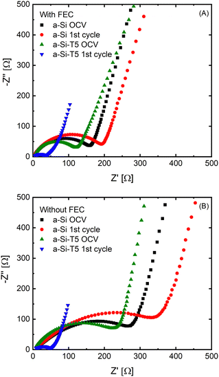
To understand the effect of the TiO2 deposition on the Li diffusion kinetics, electrochemical impedance spectroscopy (EIS) measurements of a-Si and a-Si-T5 were performed at open circuit voltage after cell assembly and after 1 charge–discharge cycle (Fig. 2). Two types of electrolytes were used for the evaluation of coating effect – an electrolyte with 10 wt% FEC (Fig. 2A) and FEC-free electrolyte (Fig. 2B), both with 1.2 M LiPF6 in EC![[thin space (1/6-em)]](https://www.rsc.org/images/entities/char_2009.gif) :
:![[thin space (1/6-em)]](https://www.rsc.org/images/entities/char_2009.gif) EMC (7
EMC (7![[thin space (1/6-em)]](https://www.rsc.org/images/entities/char_2009.gif) :
:![[thin space (1/6-em)]](https://www.rsc.org/images/entities/char_2009.gif) 3 vol%) and 2 wt% VC. All EIS plots are composed of a compressed semicircle in the middle frequency region and an inclined line in low frequency region indicating the charge transfer process and Li-ion diffusion process, respectively. The intercept at the high frequency region is attributed to the total resistance of the electrolyte, separator and the electrical contacts. The EIS data showed that the pristine electrodes based on TiO2-coated Si (a-Si-T5) had lower impedance than the uncoated samples (a-Si) with both electrolytes. The difference was largest for the FEC-free electrolyte (Fig. 2B). In addition, after one charge–discharge cycle the impedance of electrodes based on a-Si-T5 was significantly lower than the pristine electrodes, while the a-Si samples showed the opposite trend. This shows that the TiO2 coating improves the kinetics in the FEC-free electrolyte, which should lead to better performance during electrochemical cycling.
3 vol%) and 2 wt% VC. All EIS plots are composed of a compressed semicircle in the middle frequency region and an inclined line in low frequency region indicating the charge transfer process and Li-ion diffusion process, respectively. The intercept at the high frequency region is attributed to the total resistance of the electrolyte, separator and the electrical contacts. The EIS data showed that the pristine electrodes based on TiO2-coated Si (a-Si-T5) had lower impedance than the uncoated samples (a-Si) with both electrolytes. The difference was largest for the FEC-free electrolyte (Fig. 2B). In addition, after one charge–discharge cycle the impedance of electrodes based on a-Si-T5 was significantly lower than the pristine electrodes, while the a-Si samples showed the opposite trend. This shows that the TiO2 coating improves the kinetics in the FEC-free electrolyte, which should lead to better performance during electrochemical cycling.
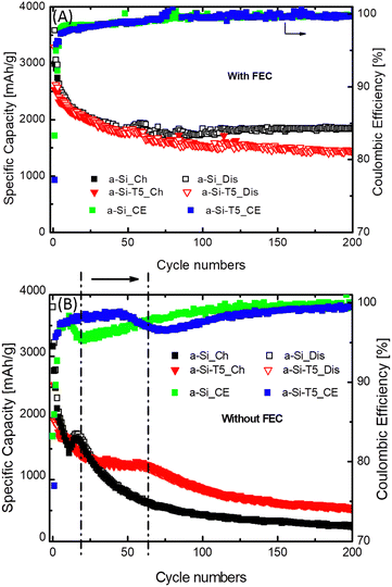
This difference in performance was further confirmed by galvanostatic cycling in coin cells vs. Li–metal reference electrode (Fig. 3 and Fig. S7–S10, ESI†). As expected, cells cycled with FEC-containing electrolyte retain relatively stable performance over the course of 200 cycles due to the improved SEI formation properties of the FEC.28–30 Predictably, the uncoated Si (a-Si) anode without FEC additive in the electrolyte suffers from fast capacity decay. However, the coating with 3 nm TiO2 (a-Si-T5) provides an improvement in capacity retention without the addition of FEC additive in the electrolyte. A careful examination revealed that the a-Si electrodes without FEC experience a fast degradation after only a few cycles (18 cycles) whereas a-Si-T5 exhibits relatively stable performance for approximately 60 cycles. Noteworthy, the initial Coulombic efficiency is significantly lower for a-Si-T5 than a-Si for both electrolytes, which is most likely due to irreversible lithiation of the TiO2-coating during the first cycle.
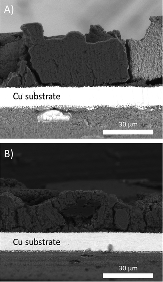
To gain further insights into the difference in cycling behavior, ex situ scanning electron microscopy (SEM) were performed on electrodes extracted after the 23rd delithiation (Fig. 4). These SEM images showed that the electrodes with uncoated a-Si (Fig. 4A) were denser, compared to the coated sample (Fig. 4B). This could be a result of electrochemical sintering where the Si nanoparticles in the uncoated sample are agglomerating as a function of electrochemical cycling, while the TiO2-coated sample maintains a more porous electrode structure.31
This difference in behavior is likely linked to the TiO2 coating and its influence on the formation of the SEI layer, which was further investigated through ex situ X-ray photoelectron spectroscopy (XPS) on pristine electrodes and electrodes extracted after the 23rd delithiation (Fig. S4–S6, ESI†). Due to the thickness of the SEI layer and the limited penetration depth of the X-ray probe, the XPS signals from Si and Ti after cycling were too weak to allow for detailed analysis of the delithiated samples (Fig. S4 and S5, ESI†).
However, XPS of F 1s showed a relative difference in the F-species on the surface of the coated vs. uncoated samples (Fig. S6, ESI†). In the delithiated uncoated sample (a-Si), the peak assigned to LiPF6 (and LixPFyO2) is higher than the peak assigned to LiF.32,33 However, in the delithiated a-Si-T5 sample the intensity of LiF is significantly higher than that of LiPF6. This indicates formation of more LiF in the SEI of the TiO2-coated sample, which is considered the key inorganic component of the SEI layer.14 This difference in the composition of the SEI layer could explain the different densities of the delithiated electrodes observed by SEM (Fig. 4). The SEI layer together with the TiO2 coating might act as a barrier between the Si nanoparticles, thus mitigating electrochemical sintering and volume change of Si during lithiation and delithiation, which can explain the enhanced cycling stability.
In conclusion, we have been able to develop a method for coating of Si nanoparticles with a thin TiO2 layer, which showed improved cycling stability in Li-ion half cells compared to the uncoated sample, when cycled with FEC-free electrolyte. This advancement can be attributed to the enhanced formation of stable SEI layer on the surface of the coated Si particles, thereby mitigating the effects of the volume changes during (de)lithiation and avoiding electrochemical sintering of the particles. As a result, the coating serves as an artificial SEI at least during initial cycling. While there are still improvements to be made, continuing to improve the ALD coating of the Si particles may lead to even better cycling performance and thus become an alternative to the use of FEC as an additive in Si-based electrodes.
This work has been primarily funded by the Research Council of Norway within EnergiX program under grant number 280985. This work was performed within MoZEES, a Norwegian Center for Environment-friendly Energy Research (FME), cosponsored by the Research Council of Norway (project number 257653), and 40 partners from research, industry, and the public sector.
Data availability
The data supporting this article have been included as part of the ESI.†Conflicts of interest
There are no conflicts to declare.Notes and references
- T. Nagaura, Prog. Batteries Sol. Cells, 1990, 9, 209 CAS.
- J. M. Tarascon and M. Armand, Nature, 2001, 414, 359–367 CrossRef CAS PubMed.
- M. Armand and J. M. Tarascon, Nature, 2008, 451, 652–657 CrossRef CAS PubMed.
- D. Deng, M. G. Kim, J. Y. Lee and J. Cho, Energy Environ. Sci., 2009, 2, 818–837 RSC.
- H. Li, Z. Wang, L. Chen and X. Huang, Adv. Mater., 2009, 21, 4593–4607 CrossRef CAS.
- H. Cheng, J. G. Shapter, Y. Li and G. Gao, J. Energy Chem., 2021, 57, 451–468 CrossRef CAS.
- M. N. Obrovac and V. L. Chevrier, Chem. Rev., 2014, 114, 11444–11502 CrossRef CAS PubMed.
- H. Wu and Y. Cui, Nano Today, 2012, 7, 414–429 CrossRef CAS.
- X. Li, M. Gu, S. Hu, R. Kennard, P. Yan, X. Chen, C. Wang, M. J. Sailor, J.-G. Zhang and J. Liu, Nat. Commun., 2014, 5, 4105 CrossRef CAS PubMed.
- G. G. Eshetu and E. Figgemeier, ChemSusChem, 2019, 12, 2515–2539 CrossRef CAS PubMed.
- N. Yuca, O. S. Taskin and E. Arici, Energy Storage, 2020, 2, e94 CrossRef CAS.
- D. Zhang, J. Lu, C. Pei and S. Ni, Adv. Energy Mater., 2022, 12, 2103689 CrossRef CAS.
- B. Chen, D. Xu, S. Chai, Z. Chang and A. Pan, Adv. Funct. Mater., 2024, 2401794 CrossRef CAS.
- D.-Y. Han, H. Y. Jang, S. Kim, J. Y. Kwon, J. Park, S. Back, S. Park and J. Ryu, Energy Storage, Materials, 2024, 65, 103176 Search PubMed.
- Y.-F. Tian, S.-J. Tan, C. Yang, Y.-M. Zhao, D.-X. Xu, Z.-Y. Lu, G. Li, J.-Y. Li, X.-S. Zhang and C.-H. Zhang, Nat. Commun., 2023, 14, 7247 CrossRef CAS PubMed.
- V. Etacheri, O. Haik, Y. Goffer, G. A. Roberts, I. C. Stefan, R. Fasching and D. Aurbach, Langmuir, 2012, 28, 965–976 CrossRef CAS PubMed.
- N.-S. Choi, K. H. Yew, K. Y. Lee, M. Sung, H. Kim and S.-S. Kim, J. Power Sources, 2006, 161, 1254–1259 CrossRef CAS.
- R. Jung, M. Metzger, D. Haering, S. Solchenbach, C. Marino, N. Tsiouvaras, C. Stinner and H. A. Gasteiger, J. Electrochem. Soc., 2016, 163, A1705 CrossRef CAS.
- M. Schnabel, E. Arca, Y. Ha, C. Stetson, G. Teeter, S.-D. Han and P. Stradins, ACS Appl. Energy Mater., 2020, 3, 8842–8849 CrossRef CAS.
- Z. Li, J. Su and X. Wang, Carbon, 2021, 179, 299–326 CrossRef CAS.
- H. Zhu, M. H. A. Shiraz, L. Liu, Y. Zhang and J. Liu, Appl. Surf. Sci., 2022, 578, 151982 CrossRef CAS.
- Y. Bai, D. Yan, C. Yu, L. Cao, C. Wang, J. Zhang, H. Zhu, Y.-S. Hu, S. Dai, J. Lu and W. Zhang, J. Power Sources, 2016, 308, 75–82 CrossRef CAS.
- L. Qiao, Z. Yang, X. Li and D. He, Surf. Coat. Technol., 2021, 424, 127669 CrossRef CAS.
- S. Casino, P. Niehoff, M. Börner and M. Winter, J. Energy Storage, 2020, 29, 101376 CrossRef.
- E. M. Lotfabad, P. Kalisvaart, A. Kohandehghan, K. Cui, M. Kupsta, B. Farbod and D. Mitlin, J. Mater. Chem. A, 2014, 2, 2504–2516 RSC.
- E. Memarzadeh Lotfabad, P. Kalisvaart, K. Cui, A. Kohandehghan, M. Kupsta, B. Olsen and D. Mitlin, Phys. Chem. Chem. Phys., 2013, 15, 13646–13657 RSC.
- G. Jeong, J.-H. Kim, Y.-U. Kim and Y.-J. Kim, J. Mater. Chem., 2012, 22, 7999–8004 RSC.
- E. Markevich, G. Salitra and D. Aurbach, ACS Energy Lett., 2017, 2, 1337–1345 CrossRef CAS.
- Y. Jin, N.-J. H. Kneusels, L. E. Marbella, E. Castillo-Martínez, P. C. M. M. Magusin, R. S. Weatherup, E. Jónsson, T. Liu, S. Paul and C. P. Grey, J. Am. Chem. Soc., 2018, 140, 9854–9867 CrossRef CAS PubMed.
- T. Hou, G. Yang, N. N. Rajput, J. Self, S.-W. Park, J. Nanda and K. A. Persson, Nano Energy, 2019, 64, 103881 CrossRef CAS.
- J. Shin and E. Cho, Chem. Mater., 2018, 30, 3233–3243 CrossRef CAS.
- B. Philippe, R. Dedryvère, J. Allouche, F. Lindgren, M. Gorgoi, H. K. Rensmo, D. Gonbeau and K. Edström, Chem. Mater., 2012, 24, 1107–1115 CrossRef CAS.
- B. Philippe, R. Dedryvère, M. Gorgoi, H. K. Rensmo, D. Gonbeau and K. Edström, Chem. Mater., 2013, 25, 394–404 CrossRef CAS.
Footnotes |
| † Electronic supplementary information (ESI) available: Experimental section, detailed electrochemical evaluation, detailed SEM, TEM and XPS analyses. See DOI: https://doi.org/10.1039/d4cc05458j |
| ‡ Present address: FAAM, Strada Statale via Appia 7 bis – 81030, Teverola (CE), Italy. |
| This journal is © The Royal Society of Chemistry 2024 |


