
 Open Access Article
 This Open Access Article is licensed under a Creative Commons Attribution-Non Commercial 3.0 Unported Licence
Concrete-based energy storage: exploring electrode and electrolyte enhancements
Deeksha N. Bangeraa,
Sudhakar Y. N. *b and
Ronald Aquin Nazareth*a
*b and
Ronald Aquin Nazareth*a
aDepartment of Chemistry, St Aloysius (Deemed to be University), Mangaluru, 575003, India. E-mail: ronald.nazareth@gmail.com
bDepartment of Chemistry, Manipal Institute of Technology, Manipal Academy of Higher Education, Manipal, 576104, India. E-mail: sudhakar.yn@manipal.edu
First published on 11th September 2024
Abstract
The exploration of concrete-based energy storage devices represents a demanding field of research that aligns with the emerging concept of creating multifunctional and intelligent building solutions. The increasing need to attain zero carbon emissions and harness renewable energy sources underscores the importance of advancing energy storage technologies. A recent focus has been on structural supercapacitors, which not only store electrochemical energy but also support mechanical loads, presenting a promising avenue for research. We comprehensively review concrete-based energy storage devices, focusing on their unique properties, such as durability, widespread availability, low environmental impact, and advantages. First, we elucidate how concrete and its composites revolutionize basic building blocks for the design and fabrication of intrinsically strong structural materials. Afterward, we categorized concrete into two major parts of a supercapacitor, i.e., electrode and electrolyte materials. We further describe the synthesis of concrete-based electrodes and electrolytes and highlight the main points to be addressed while synthesizing porous surface/electroactive matrices. The incorporation of carbon, polymers, metals, etc., enhances the energy density and durability of electrode materials. Furthermore, as an electrolyte, how concrete accommodates metal salts and the mode of diffusion/transport have been described. Although pure concrete electrolytes exhibit poor ionic conductivity, the addition of conducting polymers, metal/metal oxides, and carbon increases the overall performance of energy storage devices. At the end of the review, we discuss the challenges and perspectives on future research directions and provide overall conclusions.
Introduction
Given the recent decades of diminishing fossil fuel reserves and concerns about greenhouse gas emissions, there is a pressing demand for both the generation and effective storage of renewable energy sources.1,2 Hence, there is a growing focus among researchers on zero-energy buildings, which in turn necessitates the integration of renewable energy sources and effective energy storage solutions. Structural energy storage devices have been developed for use in various sectors, including automotive aerospace and building construction, to meet the demands of such energy systems. These devices offer advantages such as weight reduction, minimal maintenance expenses, and the ability to store and convert energy efficiently.3–5 Compared with traditional energy storage devices, concrete-based energy storage devices play a unique role in achieving zero-energy buildings due to their scalability, cost-effectiveness, and integration capabilities within building structures. Researchers have developed concrete supercapacitors that self-assemble during the curing process, eliminating the need for separate mesh electrodes and allowing carbon black to form connected electrode structures within the concrete. This innovative approach leverages the fractal-like structure of concrete to create carbon electrodes with a large surface area, enhancing the energy storage capacity. The scalability and cost-effectiveness of concrete-based devices make them a practical solution for zero-energy buildings, offering a sustainable and reliable energy storage option that aligns to reduce energy consumption and promote environmental sustainability.6Concrete, the cornerstone of modern infrastructure, boasts a legacy dating from two millennia ago to the illustrious Roman Empire. When a blend of water, aggregates, and cement is forged into a strong composite through hardening, concrete is durable, affordable, aesthetic, and accessible. However, amidst its virtues lie a series of challenges that threaten its longevity. From the effects of surface abrasion, erosion, and cracking to the relentless march of time, accompanied by temperature fluctuations, salt crystallization, and water infiltration, concrete faces a wide array of challenges. These are compounded by insidious chemical opponents such as alkali-aggregate reactions, carbonation, sulfate attacks, and the corrosion of reinforcing steel, all of which are conspiring to weaken its structural integrity.7 The lack of advanced design and assessment tools and delayed maintenance significantly contribute to the deterioration of concrete structures.8 The strategic placement of conductive fillers throughout concrete forms a consistent and strong pathway for improving conductivity within the material. This unique feature allows concrete to exhibit exceptional electrical conductivity. When subjected to external forces, the conductive framework within the concrete transforms, thereby influencing its electrical characteristics, specifically the electrical resistance. This innovative approach enables the detection of stress, strain, cracks, and structural damage in concrete structures in both static and dynamic scenarios. According to the concept depicted in Fig. 1, the conductive network established by these fillers functions as a ‘nervous system’, transmitting electrical signals in response to internal and external stimuli to a central computational hub, essentially acting as a sophisticated ‘brain’, mirroring human-like responsiveness. Fig. 1 encapsulates the comprehensive research framework underpinning the realm of sensing concrete. Transitioning from structural to multifunctional materials, sensing concrete injects a fresh wave of innovation and dynamism into construction materials. With its dual nature of structural integrity and sensing capabilities, sensing concrete has swiftly risen as a pivotal focal point within the structural health monitoring (SHM) domain. Reflecting on the discourse presented earlier, it becomes evident that the core of crafting sensing concrete lies in infusing it with conductivity through the judicious selection of matrix materials, functional fillers, and dispersion agents, alongside meticulous control of their blending ratios. Despite these achievements, numerous hurdles persist in the practical realization of sensing concrete, posing ongoing challenges to its efficient fabrication and implementation.9
 | ||
| Fig. 1 Overall research framework of sensing concrete. Reproduced from ref. 9 with permission from AIP, copyright 2024. | ||
In the ever-evolving landscape of energy storage technologies, the quest for more efficient and sustainable solutions continues uninterrupted. Due to global energy shortages and increasing pollution concerns, novel energy storage systems (ESSs) have emerged. Traditional ESSs include batteries, dielectric capacitors, and supercapacitors. Supercapacitors (also called electric double-layer capacitors or ultracapacitors), often hailed as the bridge between traditional capacitors and batteries, have emerged as promising contenders in this pursuit. Due to their rapid energy storage and release, high power density, and exceptional cycle life, supercapacitors are receiving increased attention for applications ranging from renewable energy integration to electric vehicles and portable electronics.
Supercapacitor components and their classification
Supercapacitors, as energy storage devices, operate on the concept of a battery. Comprising two conductive electrodes, one positively and the other negatively charged, they are divided by a separator, with an electrolyte combined between them as shown in Fig. 2a. Supercapacitors are categorized into three classifications depending on the composition of the electrodes: electrochemical double-layered capacitors (EDLCs), pseudo capacitors, and hybrid supercapacitors (as shown in Fig. 2b). In the realm of EDLC, energy is stored through the electrostatic separation of ions, leading to the creation of a Helmholtz double layer (HDL) at the juncture of the electrolyte and the electrode.12 When a voltage is applied to the supercapacitor's electrodes, it leads to the buildup of charges on these electrodes. This buildup results in a potential disparity across the electrolyte, prompting positive and negative ions to move toward electrodes with opposite charges.13 As the solvent molecules become polarized and adhere to the electrode surface, they effectively block oppositely charged ions from binding to the electrodes. This process leads to the formation of an electrostatic double layer on the electrode surface. Each HDL can be likened to a standard capacitor, with the polarized solvent molecules serving as a dielectric medium.14,15 Largeot and colleagues delved into the correlation between porosity and capacitance in a supercapacitor.16 Their research revealed that when the pore size is nearly equal to the size of ions, it results in the highest capacitance value. This underscores the significance of both total porous volume and pore size distribution in influencing the capacitance of an EDLC. Unlike other mechanisms, EDLC involves no chemical reaction, enabling it to withstand a vast number of charging–discharging cycles, thus boasting an extended lifespan. Additionally, its rapid charge–discharge capability allows for a substantial power density, making it a compelling choice for energy storage applications.17 The pseudo capacitor effectively retains electrical energy through a reversible faradaic charge transfer process that takes place between the electrode and the electrolyte. This distinctive mechanism allows for the efficient storage and release of energy within the supercapacitor system. When a supercapacitor's electrodes are subjected to a voltage, electrolyte ions migrate towards the electrodes of opposite charge, establishing a double layer at the electrolyte–electrode boundary. In contrast, within a pseudo-capacitor, certain selectively adsorbed electrolyte ions infiltrate the double layer to convey their charge to the electrodes. This intricate charge transfer process is facilitated by highly reversible mechanisms such as redox reactions, intercalation, and electro-sorption.18 A pseudo capacitor has the ability to store a greater quantity of charge compared to an EDLC, resulting in a proportionally higher specific energy output.19 A hybrid supercapacitor integrates elements of both EDLC and pseudo-capacitor technologies, enhancing its overall energy storage capabilities through a synergistic approach.20 The pseudo-capacitive electrode enhances the specific capacitance, working voltage, and specific energy of the supercapacitor, whereas the double-layer capacitive electrode offers improved cyclic stability and higher specific power.13,19,21 Thus, a hybrid supercapacitor demonstrates significantly enhanced electrochemical performance. Hybrid supercapacitors can also be developed using combinations of materials with pseudocapacitive and double-layer capacitive properties, further boosting their overall efficiency and capabilities.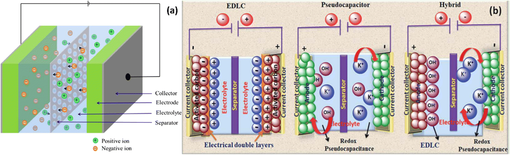 | ||
| Fig. 2 Schematic representations showing (a) components of supercapacitor. Reproduced from ref. 10 with permission from Elsevier, copyright 2024 and (b) types of supercapacitors. Reproduced from ref. 11 with permission from RSC, copyright 2024. | ||
Batteries excel at high energy density but exhibit relatively moderate power density, whereas dielectric capacitors show impressive power density but fall short in energy density. When evaluated based on criteria such as cycle life, specific power, charge–discharge speed, cell voltage, and operational expenses, supercapacitors have emerged as the superior choice among this array of devices.22 Compared to batteries, supercapacitors offer distinct advantages. Unlike batteries, which may require hours for charging and discharging, supercapacitors accomplish this task within minutes. Furthermore, they boast an exceptionally longer lifespan, enduring millions of cycles instead of mere thousands. In batteries, which rely on chemical reactions for energy storage, supercapacitors store energy through the accumulation of electrically charged ions on their electrode surfaces. Table 1 outlines a comparison of the fundamental performance metrics among capacitors, batteries, and supercapacitors. These parameters play a pivotal role in shaping the performance of supercapacitors.23–25
| S. no. | Parameters | Capacitor | Supercapacitor | Battery | Reference |
|---|---|---|---|---|---|
| 1 | Specific energy (W h kg−1) | 0.01–0.1 | 1–10 | 10–120 | 24–27 |
| 2 | Specific power (W kg−1) | 104–107 | 102–105 | 1–103 | 26 |
| 3 | Discharge time | 10−6–10−3 s | Seconds to minutes | 0.3–3 h | 23 |
| 4 | Charge time | 10−6–10−3 s | Seconds to minutes | 1–4 h | 23 |
| 5 | Cycle life | Almost infinite | >100![[thin space (1/6-em)]](https://www.rsc.org/images/entities/char_2009.gif) 000 000 |
500–2000 | 24 |
Positioned as a versatile electrical energy storage solution, structural supercapacitors are poised to not only bear mechanical loads but also deliver valuable electrical performance. Furthermore, structural supercapacitors have the potential to strike a balance, providing a foundation for combining the power density of dielectric capacitors with the substantial energy density typical of batteries. In the search for a perfect structural supercapacitor, the ultimate goal is to attain both the energy storage capacity found in conventional supercapacitors and the load-bearing capability similar to traditional structural components. However, the pursuit of this ideal is often limited by the inherent trade-off between the electrical and mechanical attributes of structural electrolytes, along with the challenges posed by the rigid contact between the electrolyte and electrode. Crucially, safety concerns must remain at the forefront when employing organic electrolytes and adopting gentle and neutral electrolytes for supercapacitors represents a potential remedy. Nevertheless, the formidable obstacle of achieving substantial energy density remains a primary hindrance to the widespread adoption of supercapacitors in commercial applications.28,29 We have critically reviewed both electrodes and electrolytes, which are made up of either concrete or its composites for supercapacitor applications.
Electrode materials play a crucial role in energy storage devices and are widely recognized in the field.30,31 Consequently, the ideal electrode material should exhibit exceptional electrical conductivity, a porous structure, a substantial specific surface area, and robust resistance to both temperature variations and chemical influences.32–34 By enabling the efficient conversion and storage of electrical energy, these materials play a pivotal role in various applications, from batteries to supercapacitors and fuel cells. Their selection and design profoundly impact the performance, capacity, and longevity of energy storage devices. As we strive for sustainable and high-performance energy storage solutions, the properties and characteristics of electrode materials serve as a guiding example for innovation and progress in this dynamic field. The relationship between pore size and the performance characteristics of electrode materials in energy storage devices is a delicate balance. On one hand, electrode materials with smaller pores tend to offer higher capacitance and, consequently, higher energy density. This is because the smaller pores provide a larger surface area for charge storage, allowing for more efficient utilization of the available volume. However, this comes at the cost of increased equivalent series resistance (ESR) within the device. The smaller pores create more resistance to the flow of current, which can limit the power density of the system. This is a crucial consideration, as applications that require high peak currents, such as in power-intensive applications, would benefit more from electrode materials with larger pores that can facilitate faster charge and discharge rates. Conversely, for applications where higher energy density is the primary concern, such as in energy storage devices for long-duration use, the trade-off favors electrode materials with smaller pores, even at the expense of slightly reduced power density. This is because the higher capacitance and energy density offered by the smaller pores can outweigh the impact of the increased ESR in these use cases.35,36 Carbon-based materials, such as activated carbons, carbon nanotubes, and graphene, are widely used due to their high specific surface area, good electrical conductivity, and low cost. Activated carbons are the most commonly used electrode materials, with specific surface areas. Carbon nanotubes offer unique pore structures, good mechanical and thermal stability, and superior electrical properties, making them attractive for high-power applications. Graphene, with its exceptional electrical and mechanical properties, has shown promise in enhancing the capacitance and rate capability of supercapacitors. Metal oxides, such as ruthenium oxide, nickel oxide, and manganese oxide, are also explored as electrode materials due to their high specific capacitance and low resistance. Conducting polymers, like polyaniline, offer the advantage of easy synthesis and high conductivity, but suffer from poor cycling stability.13 Concrete can function as an electrode in energy storage devices by exploiting its integral properties to facilitate the storage and release of electrical energy. Typically, this involves impregnating concrete with conductive materials or coatings to enhance its electrochemical properties. When used as an electrode, concrete can store electrical energy through processes such as electrochemical capacitive storage or redox reactions, depending on the specific design of the device. The high surface area of concrete structures and their durability and abundance make them promising electrode materials for use in energy storage applications. The porous structure of concrete mixture provides abundant surface sites for electrochemical reactions, allowing for more efficient ion storage and transfer. This can significantly increase the overall energy storage capacity of supercapacitors and batteries utilizing concrete-based electrodes. Concrete electrodes are still a relatively new technology, and further research and development are needed to improve their performance, efficiency, and cost-effectiveness.37 The lack of standardization in the manufacturing process and testing procedures for concrete electrodes hinders their widespread adoption. Standardization would help ensure consistency in performance and quality across different manufacturers and applications.38,39
Electrolytes are equally vital components within energy storage devices. These structural electrolytes must strike a harmonious balance between mechanical strength and ionic conductivity, enabling the seamless fusion of electrochemical and mechanical performance.40 Crucial considerations in the choice of an electrolyte include factors such as ion size and type, ion concentration, electrode materials, and the interplay of ions with their surroundings. The choice of electrolyte can influence the cycle longevity, capacitance, and energy or power density of the system.41,42 Electrolytes can be categorized based on their physical state as either liquid or solid, depending on their existing form.43,44 In the early days of energy storage technology, liquid electrolytes were favored due to their exceptional ionic conductivity and their ability to facilitate strong electrode–electrolyte interactions.45,46 Nevertheless, liquid electrolytes have certain drawbacks, including potential leakage, flammability, and toxicity.47 Currently, prevalent solid electrolytes include both ceramic-based and polymer-based variants.48–50 While ceramics are widely acknowledged as structurally robust materials, their ionic conductivity tends to be notably limited, especially at ambient temperatures, owing to the substantial impediments posed by high barriers to the motion of ionic defects within ceramics. Conversely, polymer-based electrolytes exhibit comparatively enhanced ionic conductivity but often suffer from reduced mechanical strength. Additionally, it is worth noting that in the majority of instances, polymers are flammable and possess inherent toxicity.51–53 Concrete-based electrolytes offer a novel solution to the safety concerns associated with traditional liquid or gel electrolytes used in energy storage systems such as rechargeable batteries and supercapacitors. Instead of relying on flammable solvents and salts, these innovative electrolytes utilize concrete, a sturdy composite material, as both the structural support and the medium for ion conduction. By integrating ionic species within its matrix, concrete enables safe and efficient ion transport while eliminating the risks of leakage and evaporation. This solid-state approach enhances safety and provides additional mechanical strength and stability to the energy storage device, boosting its durability and reliability. Unlike traditional electrolytes where ion transport occurs in a liquid or gel medium, ions move through the solid matrix in concrete-based electrolytes, offering a unique energy storage mechanism. Moreover, the abundance and affordability of concrete make these electrolytes cost-effective for large-scale applications, potentially reducing production costs. Additionally, concrete-based electrolytes have the potential to form a stable interface with electrodes, improving the energy density and cycling life. Overall, concrete-based electrolytes represent a promising advancement in energy storage technology, offering both safety and performance benefits. Water-based electrolytes are electrolytes that are primarily composed of water. These electrolytes are used in various applications, including batteries, due to their unique properties and advantages. Water-based electrolytes are considered safer and more environmentally friendly than organic electrolytes, as they pose lower risks of flammability and toxicity. In the context of batteries, water-based electrolytes are being explored as alternatives to organic electrolytes in lithium-ion batteries to enhance safety and sustainability. These electrolytes play a crucial role in facilitating ion transport and energy storage in various systems, contributing to the development of safer and more efficient technologies.54–56 Concrete-based electrolytes offer distinct advantages over water-based electrolytes, showcasing superior long-term durability, scalability, and cost-effectiveness. Unlike water-based electrolytes, concrete-based electrolytes leverage the inherent durability and stability of cement, ensuring prolonged performance without degradation. This long-term durability makes concrete-based electrolytes ideal for applications requiring sustained functionality over extended periods.54,55 The pivotal element for batteries and other energy storage devices offering high energy density, extended cycle life, and superior safety lies in their choice of appropriate electrolytes.57
Structure and the properties of concrete
Cement stands as an innovative entrant in the realm of solid electrolytes, offering a fresh perspective. Its remarkable environmental adaptability, that is its ability to withstand and perform well in various environmental conditions such as exposure to changing temperatures, humidity, chemical influences, and other external factors, and resistance to fire render cement an attractive choice as a solid electrolyte and lightweight.58–60 Concrete can be made lightweight by incorporating lightweight aggregates like expanded polystyrene (EPS) or ceramsite into the mixture. Lightweight porous concrete, like expanded polystyrene concrete (EPSC) and ceramics–cement-based porous material (CCPM), introduces a significant amount of pores, which results in a lighter and more porous material. These porous materials exhibit excellent energy-absorbing properties, making them ideal for civil defense projects. EPS is lightweight due to its cellular structure. When used as an aggregate in concrete, it contributes to the creation of lightweight and porous concrete.61 Cement plays a crucial role in concrete by binding the aggregates together, creating a synthetic stone-like material. Typically accounting for about 10 to 15% of the weight of a standard concrete mix, cement comprises four primary oxides: CaO, SiO2, Al2O3, and Fe2O3, although their proportions vary based on the specific type of cement being used. Upon mixing with water, cement undergoes hydration, forming calcium silicate hydrate (CSH) and Ca(OH)2. CSH serves as the primary hydration product that enhances concrete strength, while Ca(OH)2 influences the pH of concrete, playing a role in its durability. Due to its high resistivity and relative impermeability, hardened cement paste can effectively serve as a separator in a supercapacitor. However, for concrete/cement paste to function as an effective separator in a supercapacitor, it should not only be porous but also offer ionic conductivity.62 By incorporating additional alkaline materials or salts, the ionic conductivity of hardened concrete/cement paste can be enhanced, making it a suitable separator material for supercapacitors. Concrete comprises three primary components: cement, aggregates, and water. When water is added to a blend of cement and aggregates (both fine and coarse), it initiates a chemical reaction known as hydration, transforming the mixture into a solid material resembling rock, which is concrete. Within concrete, cement acts as the binding agent for the aggregates, while the aggregates contribute strength as fillers. The addition of water serves the essential role of hydrating the cement, influencing both fresh and hardened characteristics of the concrete. Concrete, while inherently porous and insulating when dry, transforms into a proficient ionic conductor in moist environments. This transformation is facilitated by the pore water content and the elevated basicity resulting from the presence of calcium hydroxide, sodium, and potassium salts inherent in cement. Such characteristics render concrete a favorable material choice for integration into supercapacitors.63Using the special features of cement, concrete-based supercapacitors are a new way to store energy. They can be used in many ways. For example, they could be put into building materials such as concrete to store energy for applications such as lights or sensors. They could also be used as backup power for renewable energy systems. Concrete structures integrated with cement-based sensors can autonomously detect damage, such as cracks, and monitor environmental conditions like temperature and humidity. This capability provides critical information regarding the structural health of buildings, enabling timely alerts for occupants to evacuate in the event of a dangerous situation. Additionally, cement-based sensors can be utilized in infrastructure such as bridges and tunnels to identify deformations and monitor crack progression, offering alarms for issues like differential settlement and leakage.64,65 Scientists are still working on improving them and finding more ways to use them. Like regular batteries, concrete-based supercapacitors usually cannot store as much energy.
Battery energy storage technologies, including lithium-ion, lead acid, sodium–sulfur, and redox flow batteries (Table 2), each have unique characteristics that make them suitable for various applications. Lithium-ion batteries are known for their high energy density, exceptional efficiency, and long cycle life, making them ideal for portable electronics, electric vehicles, and grid-scale energy storage.71 In contrast, lead acid batteries, with their lower energy density and efficiency, are more affordable and reliable, commonly used in vehicles for starting and backup power supplies.66 Sodium–sulfur batteries stand out with their high energy density and good efficiency, operating at elevated temperatures, and can be primarily used for grid-scale storage in renewable energy systems.67,68 Redox flow batteries, while having lower energy density and efficiency, excel in long-duration energy storage due to their unique liquid electrolyte system.69,70 The different types of batteries mentioned in Table 2 share a certain similarities with concrete-based systems in that they integrate the energy storage components directly into the overall system, rather than having a standalone battery pack. This allows for a more seamless integration with the built environment, similar to how concrete-based storage is embedded within the building materials. While the batteries and concrete-based storage systems share these similarities, there are also key differences in terms of energy and power density, efficiency, and specific applications. Concrete-based energy storage, on the other hand, utilizes concrete to store energy, which can later be converted back into electricity. While concrete-based systems and batteries serve similar applications in grid-scale energy storage especially in integrating renewable energy and providing backup power they differ significantly in their mechanisms and characteristics. Concrete storage is better suited for long-duration energy needs due to its lower energy density, whereas batteries are more effective for short-duration, high-power applications.
One major challenge is finding a type of liquid that works well with cement and still allows the supercapacitor to work effectively. Cement materials exhibit high porosity, facilitating extensive ion accumulation during the charging and discharging phases of concrete-based supercapacitors. Additionally, the malleability of cement enables supercapacitors to be molded into diverse configurations, ensuring adaptability to various applications and design specifications. This significant difference has been attributed to the conductivity of concrete.73 The exploration of conductive concrete involved the incorporation of various types of conductive fillers or phases, either in particle or fiber form, within the cement matrix, establishing an innovative approach to the study. Recent research findings have underscored the significance of filler size and dispersion on conductivity, highlighting their crucial influence on the electrical properties of concrete. Moreover, investigations have revealed that the volume or quantity of the filler directly impacts the concrete conductivity, showing that even low-volume fractions of fillers can enhance the conductivity. Intriguingly, studies have identified a minimum filler content of 0.8% of the concrete volume as essential for achieving favorable conductivity, challenging previous notions about the filler content required for conductivity enhancement.74
In this review, we discuss a complete, comprehensive topic of concrete material-based electrodes, electrolytes, and their composites, such as polymer-coated, carbon-doped composites with suitable salts for use in energy devices. This article provides a summary of recent advancements in employing construction building materials for energy storage devices. The gradual shift to concrete-based materials in the energy storage sector presents an attractive opportunity for leveraging the durability, abundance, and cost-effectiveness of concrete. As evidenced by this review, concrete not only underpins current development but also forms the foundation for future energy storage systems. The primary goal of this review is to further delineate the potential of concrete-based materials and their properties, design opportunities, and application prospects for meeting global-scale energy demands. This review seeks to highlight the promising potential of concrete-based materials and their role in addressing future energy needs.
Working principle of concrete-based energy storage device
The core principle underlying supercapacitors (SCs) is rooted in the concept of electrostatic capacitors, as articulated in eqn (1).
 | (1) |
This equation incorporates several key parameters: the permittivity of free space (ε0), the relative permittivity of the dielectric material (εr), the surface area of the electrodes (A), and the separation distance between the electrodes (d). The capacitance of a supercapacitor can be modified by altering the surface area and thickness of the dielectric material, following the relationship defined in eqn (1).75 This flexibility allows for optimization in energy storage performance, making supercapacitors highly adaptable for various applications. Similarly, the working principle of concrete-based supercapacitors involves the use of electrochemical double-layer capacitance to store energy. This is achieved by incorporating conductive materials, such as carbon nanotubes, graphene, or conductive fibers, into the concrete mixture. When an electrical potential is applied across the concrete-based supercapacitor, the conductive materials in the concrete act as the electrodes, and the concrete itself serves as the electrolyte. The charge is stored at the interface between the electrode materials and the electrolyte (the concrete), forming an electrical double layer. This double-layer capacitance allows the concrete-based supercapacitor to store and release energy rapidly, enabling high power density applications.
The choice of concrete/cement-based electrode materials for batteries must satisfy specific energy and power density requirements tailored to applications. At the same time, considerations such as round-trip energy efficiency, shelf life, cost, safety, and environmental impact are also essential. The energy density of a battery cell is determined by its voltage and capacity, which can be expressed through a specific eqn (2).
 | (2) |
The essential components of a battery consist of a cathode and an anode, both immersed in an electrolyte. The primary role of the electrolyte is to facilitate the movement of ions, serving as a transport medium. Although the electrolyte itself does not engage in the electrochemical reactions, its selection is crucial as it significantly influences the overall performance of the battery. Typically, this involves a combination of organic solvents and lithium salts. A separator is also a vital component, ensuring that the two electrodes remain physically apart to prevent short circuits.77 Typically, concrete-based batteries incorporate materials like lithium-ion, sodium-ion, or other battery-active materials into the concrete mix. These materials can be in the form of particles, fibers, or coatings, and they act as the active electrodes within the concrete. The working principle of concrete-based batteries is similar to traditional battery technologies but with the energy storage components integrated into the concrete mixture. When the concrete-based battery is charged, the electrochemical reactions occur within the embedded battery materials, causing the storage and release of energy. The concrete itself serves as the electrolyte, facilitating the ion transport between the positive and negative electrodes during the charge and discharge cycles.
Electrochemical measurement techniques
Cyclic voltammetry (CV)
CV is a versatile and widely employed electrochemical technique that provides a comprehensive understanding of the thermodynamic and kinetic behavior of an electrochemical system.78,79 This powerful method involves the measurements of the current response as a function of the applied potential, generating a characteristic “duck-shaped” cyclic voltammogram. The underlying principles of CV are rooted in the interplay between potentiometry and voltammetry. Potentiometry, a static measurement technique, is used to determine the electric potential of an electrochemical cell, while voltammetry involves the dynamic measurement of current as the potential is varied. By combining these approaches, CV offers a wealth of insights into the redox processes, reaction kinetics, and electrochemical properties of the system under investigation.80,81 The cyclic voltammogram is typically obtained using a three-electrode setup (i.e. working electrode, counter electrode, and reference electrode), where the potential is swept between two defined limits at a specified scan rate, typically in the range of millivolts per second. The versatility of CV lies in its ability to provide a comprehensive electrochemical fingerprint of the system, enabling researchers to delve into the thermodynamic and kinetic aspects of the electrochemical processes.82Galvanostatic charging–discharging (GCD)
In addition to CV, galvanostatic charge–discharge data is utilized to assess specific capacitance, as well as energy and power densities. These measurements are conducted at various charge densities. For instance, cyclic stability can be evaluated using the GCD curve by analyzing the duration of the charging and discharging cycles. It is important to note that there is an inverse relationship between current density and specific capacitance.83 For electric double-layer capacitor materials,84 the GCD curve exhibits a linear profile, with the value of b consistently equal to 1, signifying excellent electrochemical capacitive behavior. In contrast, pseudocapacitive materials display non-linear variations in their charging and discharging profiles.85 Meanwhile, battery-type materials are characterized by GCD curves that feature distinct plateaus.86Electrochemical impedance spectroscopy (EIS)
Electrochemical impedance spectroscopy (EIS) is a highly effective technique that provides valuable insights into the electrochemical performance of supercapacitors. It allows for the assessment of key parameters such as series resistance, charge transfer resistance, double layer capacitance, and Warburg impedance, which arises from diffusion processes.87,88 Most EIS instruments have a measurement capability limit of approximately 1010 Ω for impedance. The fundamental electrical circuit elements involved in EIS include resistors inductors, and capacitors. EIS is typically conducted using an alternating current over a frequency range of 0.01 Hz to 1 mHz.89,90 The data obtained from EIS can be represented in Nyquist and Bode plots. In a Nyquist plot, the real part of the impedance is plotted on the x-axis, while the imaginary part is plotted on the y-axis. These plots often display semicircles in the high-frequency region, indicative of faradaic redox reactions or electronic conduction at the electrode. A 45° straight line in the medium frequency range corresponds to molecular diffusion, known as the Warburg region, while a 90° straight line at low frequencies signifies the formation of a double layer on the electrode surface. The extension of the semicircle from high to medium frequencies suggests that charge transfer processes occur at the electrode–electrolyte interfaces.91 Thus, EIS serves as a crucial tool for investigating the charge transfer characteristics of the prepared electrodes.Concrete-based electrode materials
Concrete-based electrode materials exhibit a dual nature, providing both the structural strength of concrete and the electrical conductivity of advanced materials. This combination allows for the creation of multifunctional structures that can store and release electrical energy efficiently. The creation of cement-based electrodes involves two distinct techniques: blending powders and metal-coating processes. In the powder-mixing method, metal particles are directly integrated into the cement mixture, resulting in post hydration of the electrode layer. Despite its simplicity, this approach has raised health concerns due to the use of metals such as Ni-containing powders, leading to subpar electrical performance issues. Conversely, the metal-coating process of electroplating active metals onto carbon fiber (CF) meshes with iron-coated CF meshes results in a deliberately thicker coating for enhanced anode stability (Fig. 3a and b).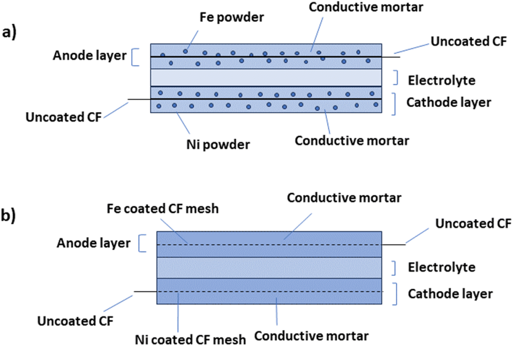 | ||
| Fig. 3 A visual representation depicting the conceptual design of an energy storage device created through (a) the powder mixing process and (b) the metal coating process. | ||
Table 3 illustrates the weight changes in the pre- and post-electroplating meshes and the calculated coating thicknesses based on the applied total electrical charge. Cement-based electrodes, enhanced with Ni and Fe metal coatings through electroplating, achieved a 7 W h m−2 peak energy density in a liquid electrolyte, maintaining an average of 6.8 W h m−2 over six charge/discharge cycles. Significantly, metal-plated cement-based electrodes outperform those created using metal or metal oxide powders. When added to cementitious materials, carbon fibers increase the conductivity, increase the strength, and reduce drying shrinkage. Overlooking costly carbon additives such as carbon black or nanotubes was strategic due to cost barriers and dispersion challenges affecting workability.92–94 Carbon-based additives such as carbon black or carbon nanotubes have been used as alternatives to metals for two primary reasons. First, their exorbitant cost presents a formidable barrier to future large-scale production. Second, their challenging dispersion properties pose a considerable impediment to workability, leading to significant adverse effects.94 Wen et al. incorporated short carbon fibers as functional additives into cement mixtures to create conductive layers. They found a general trend of decreasing resistivity in conductive cementitious mortar as the volume of carbon fibers increased.95
| Fe–CF mesh | Ni–CF mesh | |
|---|---|---|
| Initial weight (g) | 2.433 | 2.433 |
| Final weight (g) | 8.714 | 4.955 |
| Gained weight (g) | 6.281 | 2.522 |
| Theoretical thickness of the coating (μm) | 60 | 23 |
Zhang et al. made a structural supercapacitor comprising two graphene-based electrodes, sandwiching a robust sheet of cement paste infused with a 1 M KOH solution. The CV curves for structural supercapacitors, depicted in Fig. 4a, exhibit a rectangular shape at a scan rate of 100 mV s−1. This nearly ideal rectangular shape indicates the absence of pseudo-capacitance effects in these structural supercapacitors. Notably, the rectangular characteristic is more pronounced in early-stage cement paste than in late-stage cement paste. This can be attributed to decreased porosity as the cement paste undergoes hydration and hardens.96 This outcome indicates that the structure exhibits sufficient stability to serve effectively as an electrode material (Fig. 4a).99 The fabrication process involves preparing cement pastes with varying water-to-cement ratios and casting them into thin circular molds to create hardened cement paste sheets and prism molds for compressive strength testing. After curing, the thin cement paste sheets are infused with an electrolyte solution (1 M KOH) and sandwiched between two graphene electrodes to assemble the structural supercapacitor. This novel approach directly integrates energy storage capabilities within structural elements by utilizing a cement paste sheet as a separator and electrolyte reservoir, while graphene is the electrode material. The varying water-to-cement ratios allow investigation into the impact of paste porosity and workability on the electrochemical performance of these multifunctional structural supercapacitors, which can potentially enable sustainable and energy-efficient building materials.96 Incorporating 0.03% graphene oxide (GO) by weight into cement has been shown to enhance tensile strength, flexural strength, and compressive strength compared to control samples.100 The hydration crystal formation processes in cement significantly influence mechanical strength, and graphene oxide demonstrates considerable potential for practical applications.101 The improvement in the pore structure of cement composites may result from an increased rate of hydration, with the addition of GO further enhancing the strength characteristics of ordinary Portland cement (OPC) paste.102 The incorporation of graphene oxide can enhance the pore structure within cement paste, which contributes to a reduction in the sorptivity of cement composites. Meng et al. designed a battery system that incorporates electrode layers made from cement mixed with active additives. The cathode layer consists of a blend of manganese dioxide particles and cement, while the electrolyte is composed of cement, and the anode contains cement combined with zinc particles. This design offers a significant advantage over traditional protruding electrode (non-cement-based) probes, as the active materials in both the anode (zinc) and cathode (manganese dioxide) are in direct contact with the electrolyte (the pore solution within the cement paste) throughout the anodic and cathodic layers, rather than just at the interface with the electrolyte. However, the performance of this battery design was limited, achieving maximum open circuit voltages of 0.72 V and currents of 120 μA (equating to a current density of 3.8 μA cm−2). Notably, it only generated current when saturated.103
 | ||
| Fig. 4 Schematic methods of synthesis of the concrete-based electrodes and their CV graphs. Reproduced from ref. 96–98 with permission from (a) IOP, (b and c) Elsevier, copyright 2024. | ||
Cement is a commonly employed synthetic substance that contains no organic compounds. Upon mixing with water, it transforms into a material characterized by its porous nature.104 As carbon is a commonly employed electrode material, it has been combined with cement to give rise to a novel substance known as “cement–carbon”. The exceptional conductivity properties of this material make it suitable for the creation of cement–carbon electrodes. To craft these electrodes, a simple manual process is employed: a precise blend of graphite powder, cement, and deionized water is meticulously mixed using a mortar and pestle. The resulting paste is then firmly packed into the electrode cavity within a Teflon sleeve. Cement, known for its ability to bond with various materials, coupled with the cost-effectiveness of both cement and carbon, positions cement–carbon as a promising electrode material, even though its applications are still relatively limited (Fig. 4b).97 We highlight that achieving uniform dispersion within conductive materials is essential for optimizing performance. A dual strategy involving mechanical and physical dispersion techniques is utilized to address this issue. The process begins with the mechanical stirring of a mixture containing surfactants and carbon black in deionized water to create a homogeneous paste. Subsequently, cement powder is added and stirred to form a uniformly mixed slurry, which is then cast into cylindrical molds (Fig. 4c). Ensuring the proper integration of nanoscale carbon black particles within the cement matrix requires precise control of the water content to prevent any negative effects on cement hydration and the mechanical properties of the composite electrode. To address this challenge, a post-casting pressurization step is implemented to remove excess water, allowing for tight packing of composite particles and ensuring the electrode's optimal structural and conductive characteristics. By combining mechanical stirring with physical dispersion techniques, the reported study demonstrated a methodical way to enhance the performance of composite electrodes. The controlled integration of nanoscale particles and careful management of water content constitute a systematic approach for achieving the desired structural and conductive properties. The fabrication process of the supercapacitor involved meticulous steps aimed at ensuring uniformity, efficiency, and performance. Initially, after a curing period, the electrodes were precisely cut and sanded to a consistent thickness, which is crucial for optimal functionality. The subsequent use of fine-grit sandpaper to polish the electrode surfaces further enhanced their quality. The novelty lies in the particular preparation and treatment of the electrodes, ensuring uniformity and smooth surfaces, which are vital for maximizing the energy storage capacity. The unique aspect of the assembly is the use of identical electrodes, along with glass fiber filter paper and graphite paper, immersed in a KCl solution for saturation, highlighting a meticulous approach to electrolyte impregnation for enhanced supercapacitor performance.98 The predominantly rectangular shape of these CV curves signifies excellent capacitive behavior in the supercapacitors, marked by the absence of significant faradaic processes during charge–discharge cycles.105 Interestingly, as the scan rate increases from 10 mV s−1 to 200 mV s−1, there is a noticeable increase in the area under the CV curve, gradually changing the curve shape to a more shuttle-like appearance. This transformation highlights the increasing influence of polarization effects on capacitor performance at higher scan rates. The intensified polarization, reflected in the enlarged areas of the CV curves, reveals the constraints on the energy storage efficiency imposed by higher scan rates.106,107
Fig. 5 illustrates that the proportion of carbon black in the electrodes significantly impacts their electrochemical performance. A low carbon black content limits charge transfers due to its sparse distribution, leading to high resistance and reduced efficiency. As the carbon black content increases, the interconnected pathways within the electrode multiply, reducing the internal resistance and enhancing the electrical charge storage capacity. Changes in the ion and cement matrix paths visually represent this innovative insight. The novelty of this study lies in elucidating the relationships among the carbon black content, internal resistance, and electrochemical performance, which offers valuable insights for optimizing electrode design and supercapacitor efficiency.
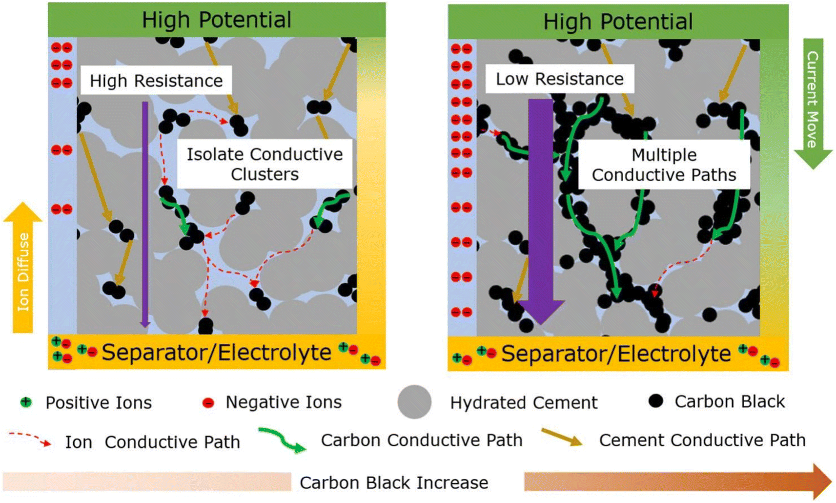 | ||
| Fig. 5 Mechanism of the cement–carbon composite supercapacitor. Reproduced from ref. 98 with permission from Elsevier, copyright 2024. | ||
The illustration provided in Fig. 6a is the energy storage mechanism within the potassium-geopolymer (KGP) cementitious composite-based capacitor. Fig. 6b shows the process of energy storage in KGP capacitors during charging. The results show that ions with opposite charges become segregated when the capacitors are charged. Specifically, the positively charged K+ ions become adsorbed onto the negative electrode, while the negatively charged [SiO4/AlO4]− ions (and potentially OH− ions) are adsorbed onto the positive electrode. This segregation results in the creation of two layers of charges with opposite polarities, separated by an effective distance ‘d’ at the interface between the electrode and the KGP matrix (Fig. 6c). Consequently, this configuration results in the formation of a capacitor structure for efficient energy storage at the electrode/KGP matrix interface.108 The CV curves reveal the electrochemical behavior of KGP capacitors 1 and 2 across different scan rates within the potential window of −0.5 to 0.5 V (Fig. 6d and e). The observed CV curves exhibit symmetric and slightly distorted rectangular shapes, indicating favorable capacitive behavior for energy storage, as noted in the literature.109 This shape provides evidence for the presence of an electrochemical double layer (EDL) mechanism within KGP cementitious capacitors, underscoring their energy storage potential. Furthermore, the energy storage mechanism inherent in KGP capacitors stems from the reversible electrostatic accumulation of ions that are adsorbed onto the surface of the steel mesh electrodes. This process substantiates the ability of capacitors to effectively store energy through electrostatic means, adding additional dimensions to their performance and application in energy storage systems.
 | ||
| Fig. 6 Energy storage mechanism in KGP capacitors. (a) KGP capacitor, (b) charging mechanism, (c) formation of a double layer capacitor. (d and e) Cyclic voltammetry curves of the KGP capacitors at different scan rates. Reproduced from ref. 108 with permission from Elsevier, copyright 2024. | ||
Fig. 7a shows the experimental setup for the CV and GCD (galvanostatic charge–discharge) tests. The electrodes are made of carbon–cement composites and are separated by an insulator. The electrolyte was 1 M KCl. The CV curves in Fig. 7b and c show the capacitance values obtained from CV tests performed on two different carbon–cement electrode samples. The main difference between the two curves is the magnitude of the capacitance. The curve in Fig. 7b shows a higher capacitance than the curve in Fig. 7c. This difference is due to the different carbon black used in the two electrode samples. Overall, the CV curves show that the capacitance values obtained from CV tests can vary depending on the specific carbon black used in the electrode samples. Fig. 7d shows that the rate-dependent capacitance is a function of the dimensionless diffusion variable, which is a measure of the ratio of the diffusion length to the electrode thickness. The capacitance values are plotted against this variable, and the resulting curve describes the rate-dependent capacitance of the carbon–cement composites. Overall, these findings highlight the unique textural properties of carbon–cement composites and their impact on the rate-dependent capacitance.6
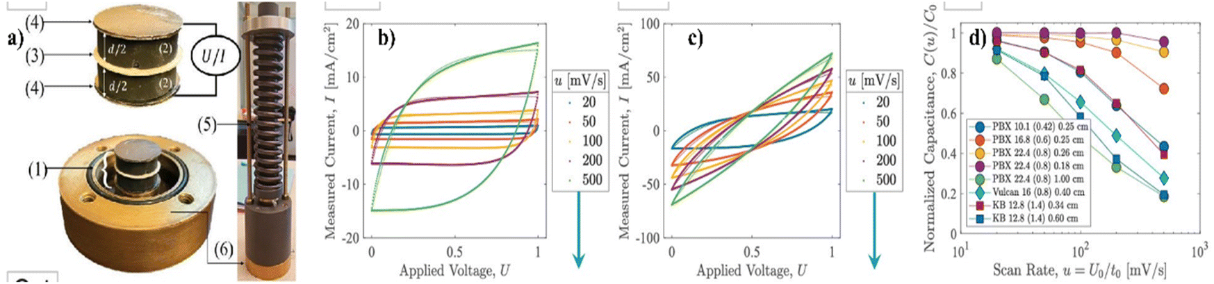 | ||
| Fig. 7 (a) (1) An electric double-layer capacitor (EDLC) composed of (2) two polished, electrolyte-saturated carbon–cement electrodes (thicknesses) (d) separated by (3) a glassy fiber membrane soaked in the same electrolyte (1 M KCl) and covered by (4) conductive graphite paper. The electrodes are (5) prestressed in (6) a closed cell to improve contact between the charge collectors and the electrodes. (b and c) Steady-state CV measurements of current, I, during cyclic charge/discharge at different scan rates, u = U0/t0, for two carbon–cement electrode samples prepared with different carbon blacks, water-to-cement ratios, and electrode thicknesses. (d) By applying eight different carbon–cement electrode materials with different carbon black materials, mix designs, and electrode thicknesses, a characteristic scaling of the rate-dependent CV capacitance is obtained, which is indicative of the high rate capability of the electrode materials. Reproduced from ref. 6 with permission from PNAS, copyright 2024. | ||
Scientists have tried different methods to create special materials from concrete that can store and release electrical energy efficiently, such as using graphene-based materials and metal coatings, to make these materials better at conducting electricity. Carbon fibers were also added to the materials to increase strength. Carbon with cement material is good at conducting electricity and could be a low-cost option for making electrodes, even though it is not widely used yet. This research provides valuable insights into optimizing the performance of concrete-based materials for various applications, particularly in the development of advanced electrode materials with enhanced conductivity and structural integrity. Therefore, creating an electroactive path or channel is crucial for preparing concrete-based electrode materials. Carbon and graphite embedded with metals provide these pathways for easy access to ions.
Concrete-based electrolytes
An electrolyte is a conduit between two electrodes of opposite charge, facilitating the transfer and equilibrium of charges between them. This transfer mechanism helps maintain a balanced environment essential for the functioning of energy storage devices. The development of efficient and safe electrolytes is crucial for the advancement of energy storage systems.110 Concrete-based electrolytes offer several advantages over traditional electrolyte materials. First, concrete-based electrolytes are known for their excellent thermal stability, which is essential for preventing thermal runaway and ensuring the safe operation of energy storage systems. Furthermore, concrete-based electrolytes have high ionic conductivity, allowing for efficient ion transport during charge and discharge processes.Fang et al. developed a cement-based electrolyte by blending cement paste with a range of alkali metal salts, including KOH, K2SO4, KCl, NOH, Na2SO4, NaCl, LiOH, and LiCl (Fig. 8a). Notably, they observed that the composite incorporating Na2SO4 exhibited the most favorable characteristics, with an impressive compressive strength of 33 MPa and an areal capacitance of 30 mF cm−2. Fig. 8a shows the CV curves of the rGO (reduced graphene oxide) foam, demonstrating that the EDLC performance was characterized by nearly rectangular shapes.45 A thorough examination of the literature revealed that the inclusion of alkaline or alkaline metal salts effectively enhanced the areal capacitance of Structural supercapacitors (SSCs). SEM (scanning electron microscope) analysis revealed distinctive characteristics between pure Portland cement and Portland cement electrolytes infused with Na2SO4. According to the SEM image of pure Portland cement, a complex three-dimensional network of porous gel material emerged, which was supplemented with needle-shaped ettringite, hexagonal plank-shaped Ca(OH)2, and an abundance of colloids. Conversely, according to the SEM images of the Portland cement electrolytes with Na2SO4, the microstructure appears more relaxed, attributed to the pronounced drying shrinkage and water expansion induced by the addition of Na2SO4. While the SEM images of both samples are similar, the incorporation of Na2SO4 notably alters the microstructure, rendering the microstructure more porous than that of pristine Portland cement. The SEM images presented in Fig. 9a and b illustrate how the presence of Na2SO4 salt results in a notable increase in the porosity of the cement.45
 | ||
| Fig. 8 Schematic methods of synthesis of concrete-based electrolyte and its CV graphs. Reproduced from ref. 45, 96, 111 and 112 with permission from (a) Elsevier, (b) IOP, (c) RSC, (d) SAGE, copyright 2024. | ||
 | ||
| Fig. 9 SEM micrographs of (a) Portland cement and (b) Portland cement with Na2SO4 alkali salt. Reproduced from ref. 45 with permission from Elsevier, copyright 2024. | ||
Nonetheless, introducing alkalis into the mix may pose a potential risk to the long-term durability and structural stability of cement-based materials.113,114 In the context of civil engineering, SSCs incorporated within cement matrix composites hold notable significance. When SSCs are seamlessly integrated into cement matrices, we effectively imbue infrastructure with the ability to not only support structural loads but also to store and manage electrical energy. This transformative fusion bridges the gap between concrete and circuitry, giving rise to infrastructure that embodies resilience, intelligence, and energy efficiency.46,96,115 However, one of the most formidable hurdles facing these SSCs lies in the creation of structural electrolytes constructed from inorganic cement-based materials. These electrolytes must excel in terms of mechanical strength, ionic conductivity, and seamless compatibility with the electrodes, a triad of demanding criteria to meet.
The porosity of the pure Portland cement electrolyte was 23.58%, showing a slight increase in porosity in the order of K2SO4 < Na2SO4 < Li2SO4 < KCl < NaCl < LiCl < KOH < NaOH < LiOH (30.51%). This indicates that the addition of alkali metal salts contributes to a marginal increase in the porosity of Portland cement electrolytes, which is attributed to the formation of hydration products within the cement pastes, as illustrated in Fig. 10a. The ionic conductivity of Portland cement electrolytes incorporating various alkali metal salts is shown in Fig. 10b. The initial ionic conductivity of the pure Portland cement was measured at 0.02 S cm−1. With the addition of different alkali metal salts, the ionic conductivity of the structural electrolytes increases, which is consistent with previously observed porosity trends ranging from 0.06 to 0.08 S cm−1. The porosity of cement electrolytes increases slightly with the addition of alkali metal salts, whereas the ionic conductivity of the structural electrolytes also increases after the addition of alkali metal salts. In Fig. 10c, the compressive strength of Portland cement electrolytes featuring various alkali metal salts is depicted. For pure Portland cement, the compressive strength was 40.6 MPa. Notably, as alkali metal salts are introduced in accordance with the porosity order, there is a decrease in the compressive strength of Portland cement electrolytes. Fig. 10d shows the multifunctional capabilities of Portland cement electrolytes enriched with various alkali metal salts; the graph shows the correlation between the ionic conductivity and compressive strength. A strategically chosen ideal point, representing the electrolyte with the highest combination of compressive strength and ionic conductivity, serves as a benchmark. The closer a data point is to this ideal, the better the multifunctional performance of the Portland cement electrolyte. According to a comprehensive assessment, Portland cement–NaSO4 has emerged as the optimal alkali metal salt for structural electrolytes in civil engineering, with a compressive strength of 32.67 MPa and an ionic conductivity of 0.062 S cm−1. This structural electrolyte outperforms others in the domain of both mechanical and electrochemical properties, marking a significant advancement for energy storage applications in civil engineering compared to relevant structural electrolytes.28,116–118
 | ||
| Fig. 10 (a) Total porosity, (b) ionic conductivity, (c) compressive strength, and (d) multifunctional performance of Portland cement electrolytes with various alkali metal salts. Reproduced from ref. 45 with permission from Elsevier, copyright 2024. | ||
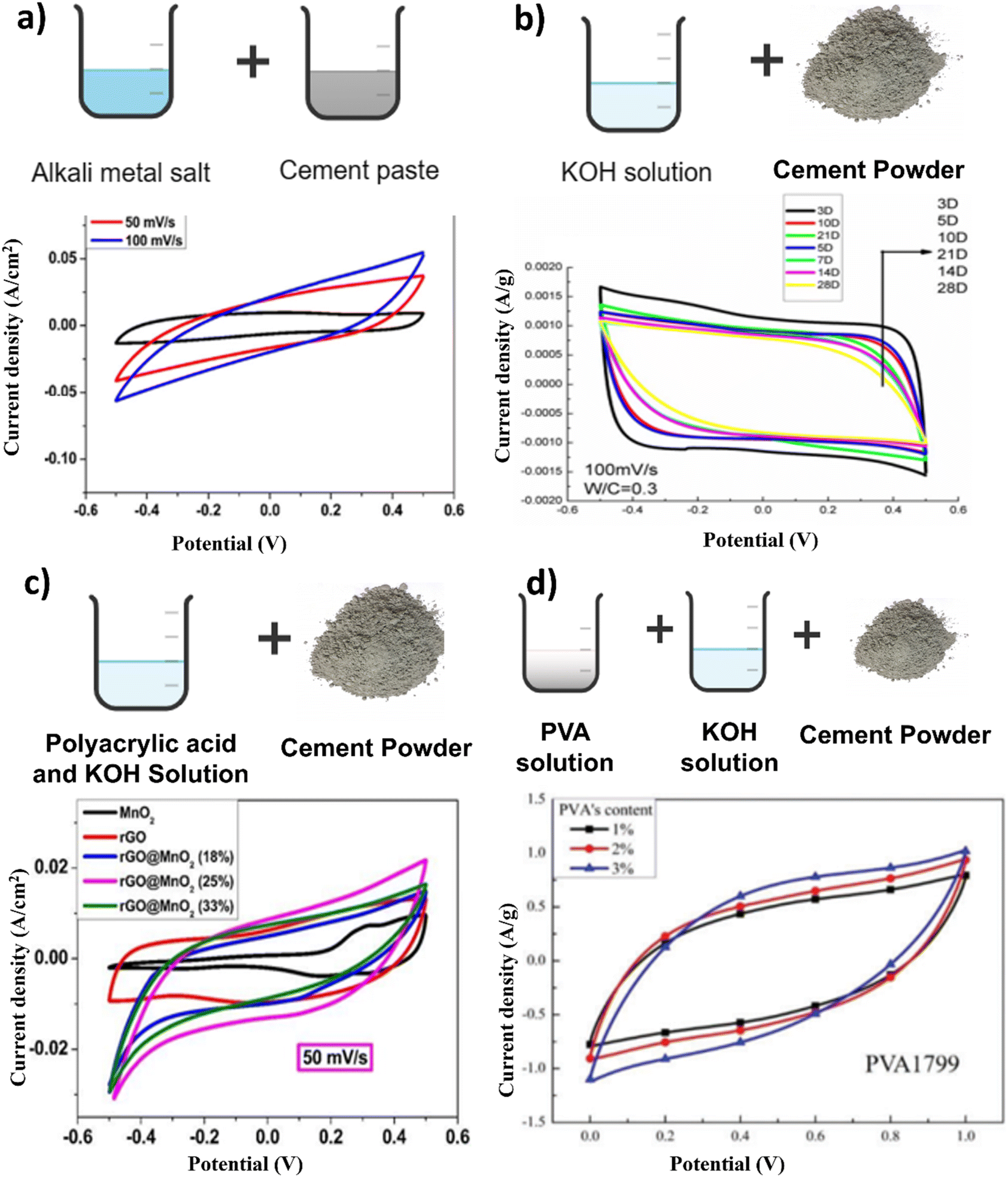
As shown in Fig. 11, the addition of H2O2 as a foaming agent significantly increased the total porosity of the cement specimens. The pore size distribution shows that most of the pores are in the “less harmful” range of 20–100 nm in diameter.120 As the H2O2 content increases, the total porosity increases, with the (Portland cement) PC0.6 specimen exhibiting the optimal balance of porosity and pore size distribution. Based on prior research, pores are classified into harmful categories based on their diameter, with pores larger than 100 nm thought to be detrimental to concrete properties.121,122 Hence, the pore structure of cement plays a crucial role in determining its electrochemical performance, particularly in terms of capacitance. From this, we can say that by carefully engineering the pore network within cement-based materials, we can unlock their full potential as high-performance energy storage devices.
 | ||
| Fig. 11 Comparative analysis of pore size distribution curves in diverse cement specimens. Reproduced from ref. 119 with permission from Elsevier, copyright 2024. | ||
Zhang et al. made an innovative breakthrough by introducing a novel SSC with a remarkable specific capacitance of 10 F g−1 and a robust compressive strength of 9.85 MPa. Their pioneering approach involved immersing Portland cement in a 1 M KOH solution, marking a significant advancement in the field (Fig. 8b).96 Fang and Zhang created structural electrolytes based on polyethylene oxide (PEO) for cement-based applications in multifunctional structural supercapacitors employing rGO@CuCo2O4 electrodes. The PEO material was modified with a combination of KOH (5%) and LiOTf (lithium trifluoromethanesulfonate) (5%) to develop two distinct structural supercapacitors. The findings indicated that an optimal 2 wt% PEO content offered the best compromise between the mechanical properties and ionic conductivity within the polymer cement electrolyte.123 Structural electrolytes for structural supercapacitors were crafted using polyacrylic acid (PAA) in conjunction with Portland cement and KOH, along with a three-dimensional rGO@MnO2 foam electrode. The process involved the creation of a PAA and KOH solution (at a concentration of 2 mol L−1), to which cement was introduced at a specific w/c (water–cement) ratio of 0.4. Vigorous mixing was employed during the preparation of these structural electrolytes (Fig. 8c). The CV curve exhibits distinct redox peaks at approximately 0.3–0.4 V, which is indicative of the characteristic pseudocapacitive behavior of MnO2 nanoparticles.124 As the PAA polymer content increased, there was a noticeable transition in the pore structure. Larger pores decreased in size, giving rise to smaller, denser pores (Fig. 12). This transformation occurred due to the filling effect facilitated by the interaction of the PAA polymeric chains with the Portland cement, resulting in a compacted structure.111
 | ||
| Fig. 12 SEM images of Portland cement–KOH. Reproduced from ref. 111 with permission from RSC, copyright 2024. | ||
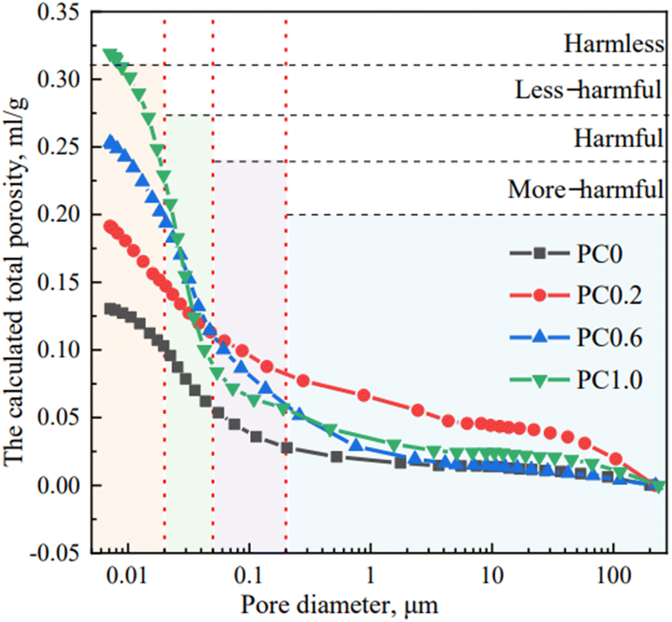
The role of salt or dopants is to enhance the energy storage capabilities of cement-based electrolytes. Precisely controlling the concentration of K3Fe(CN)6 incorporated into cement composites, driven by the remarkable solubility and electrochemical reactivity exhibited by the Fe(CN)63−/Fe(CN)64− redox pair, is another aspect of increasing the energy storage capabilities. Cement-based electrolytes were meticulously crafted, maintaining a consistent water–binder ratio (w/b) of 0.42. The polymer content, PAA, was fixed at 10% of the cement mass. The synthesis of various redox-active cement-based electrolytes was achieved by precisely controlling the addition of K3Fe(CN)6 (KFCN) to Portland cement. In the formulation process, a 50% PAA aqueous solution and KOH were added at 20% and 10% of the cement mass, respectively. Standard GB/T (Guobiao/T) 1346-2001 procedures were followed to prepare the redox-active cement-based electrolyte slurry, which was then cast into custom acrylic molds of varying sizes. Cement composites lacking potassium ferricyanide (KFCN) display a finely textured and consistent three-dimensional interconnected pore system characterized by delicate hexagonal plank-shaped Ca(OH)2, needle-like ettringite (AFt), and hydrated calcium silicate gel (C–S–H) (Fig. 13a). As the quantity of added KFCN increases, there is a corresponding increase in the number of pores, leading to a more open microstructure, as depicted in Fig. 13b–d. Fig. 13e prominently reveals the presence of numerous sizable pores dispersed throughout the microstructure of the sample. Alterations in the micromorphology of cement-based electrolytes have implications for their compressive strength, ion migration, and redox reactions.125
 | ||
| Fig. 13 (a) SEM images of various redox-active cement composites (a) KFCN-0, (b) KFCN-0.02, (c) KFCN-0.04, (d) KFCN-0.06, (e) KFCN-0.08. Reproduced from ref. 125 with permission from Elsevier, copyright 2024. | ||
The combined mechanism of charge storage as an EDL and redox reactions can be attributed to the superior performance of solid supercapacitors, as shown in Fig. 14. During the charging process, an accumulation of negatively charged ions occurs on the surface of the rGO electrode to maintain charge equilibrium, which is then released during discharge. This swift electrostatic ion adsorption and redox reaction imparts solid devices with both high-power capabilities and exceptional cycling stability. In the rGO/Fe2O3 electrode, protons can undergo adsorption near the electrode surface accompanied by faradaic reactions.126 Within the redox-active cement electrolyte, a distinctive process occurs during charging wherein K4Fe(CN)6 is adsorbed onto the rGO electrode until it reaches its reduction potential. At this point, electrons are transferred from the electrolyte to the electrode, causing the oxidation of K4Fe(CN)6 to K3Fe(CN)6. Significantly, the oxidized K3Fe(CN)6 can diffuse into the surrounding electrolyte solution, thereby enhancing the charge storage capacity of the system. This enhancement arises not only from the faradaic reaction occurring at the electrode/electrolyte interface but also from the contributions of the bulk electrolyte outside this interface.127 The seamless interplay between the rapid electrostatic adsorption of ions and faradaic redox reactions at the electrode–electrolyte interface is the key to unlocking the superior performance of these solid supercapacitors. By harnessing both the EDL formation and the redox-active nature of the materials, the devices can deliver high power output while maintaining remarkable cycling stability.
 | ||
| Fig. 14 Charge storage mechanisms for solid devices based on cement-based electrolytes. Reproduced from ref. 125 with permission from Elsevier, copyright 2024. | ||
Polymer-infused cement is a unique fusion of cement and a polymer, creating a powerful composite.128 In the modern approach, we can mix polymers with cement using polymer particles or solutions. It is now well accepted that polymers not only blend physically with cement but also chemically interact as cement hydrates. When we reach equilibrium, these interactions can improve the structure and quality of polymer-modified cement.129 Sakai's research revealed that polymer particles alter cement by creating a protective coating on the surface of cement particles.130 Polymer solutions enhance the strength of polymer-modified cement by creating connections, or crosslinks, between the polymer, calcium ions, and products of cement hydration.131 Xu and Zhang employed a novel approach utilizing a composite of cement and polyvinyl alcohol (PVA) doped with KOH to create a structural electrolyte for a multifunctional structural supercapacitor featuring graphene electrodes (Fig. 8d). Their findings revealed a direct correlation between the specific capacitance and the quantity of PVA, as well as the extent of hydrolysis. However, they noted a decrease in the specific capacitance as the degree of polymerization of PVA increased. The CV graph shows that the specific capacitance of the structural supercapacitor increases with increasing PVA content.112
J. Wang et al. prepared a structural electrolyte using an in situ polymerization method, as shown in Fig. 15. In situ polymerization enhances performance by creating a polymer within the structure of the electrolyte material itself, leading to improved mechanical and chemical stability. This method allows for uniform polymer distribution throughout the electrolyte, ensuring better adhesion between the different components. As a result, the electrolyte becomes more resistant to mechanical stress and provides enhanced support for the electrodes, resulting in improved overall performance and durability of the supercapacitor cells. Additionally, the in situ polymerization process can adapt the properties of the polymer to meet specific requirements, such as flexibility, ionic conductivity, and interfacial compatibility, further contributing to the superior performance of structural supercapacitors. The in situ polymerization method leads to the formation of a three-dimensional porous network with Portland cement, allowing for a shortened ion transport distance without sacrificing the electrolyte's mechanical properties. The microstructure becomes denser over time, contributing to the formation of a compact and integral reinforced structure. Additionally, the addition of pore-forming agents such as SnO2 creates a three-dimensional structure with an increased contact area between the electrolyte and the electrode, thus enhancing ion transport and storage. The novelty lies in using the in situ polymerization method to create the PAM–Portland cement structural electrolyte, which enhances its structural integrity and sets the stage for subsequent testing and characterization.132
 | ||
| Fig. 15 Synthetic scheme for the preparation of the PAM–Portland cement electrolyte. | ||
The assembly schematic diagram in Fig. 16 illustrates a symmetric structural supercapacitor cell, utilizing rGO/SnO21− as both the positive and negative electrodes, while PAM–Portland cement–KOH functions as the solid electrolyte. To evaluate the performance of this configuration, cyclic voltammetry, galvanostatic charge–discharge, and electrochemical impedance spectroscopy tests were performed within a two-electrode system. The cyclic voltammetry curves of the structural supercapacitor at varying scan rates are illustrated in Fig. 16b, while Fig. 16c presents the corresponding areal capacitances. It was observed that the areal capacitance significantly decreased with increasing scan rates, reaching a maximum value of 23.3 mF cm−2. As shown in Fig. 16d, the galvanostatic charge–discharge curves of the structural supercapacitor cell exhibited symmetry across different current densities, with all plots demonstrating clear linearity and symmetrical characteristics. The reduction in areal capacitance can be attributed to the decreased interaction time for ions between the electrode and electrolyte, which hampers the electrochemical reaction as the current density rises.133
 | ||
| Fig. 16 (a) Schematic diagram of a structural supercapacitor cell. (b) CV curves of structural supercapacitor cell at various scan rates, (c) areal capacitance of the structural supercapacitor calculated from CV curves, (d) galvanostatic charge/discharge curves of the structural supercapacitor with different current densities. Reproduced from ref. 132 with permission from Elsevier, copyright 2024. | ||
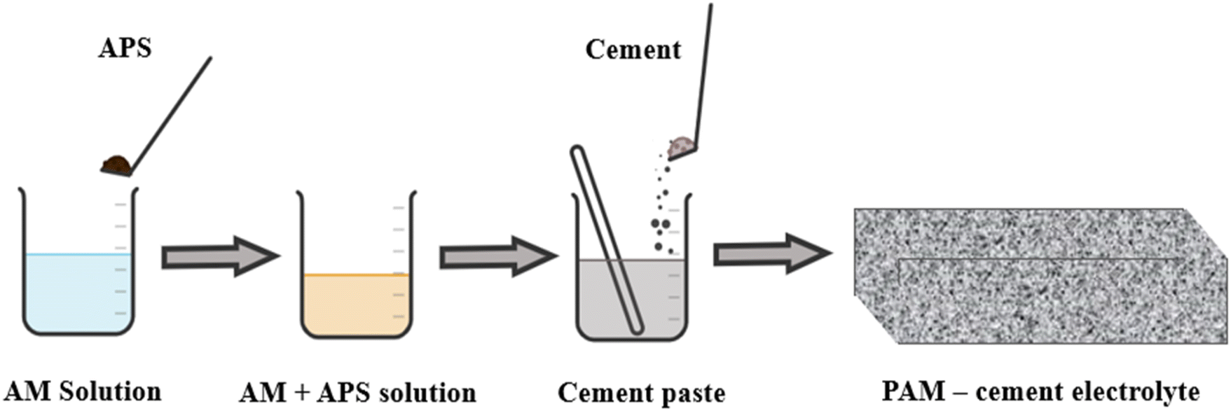
All-solid-state structural supercapacitors (ASSCs) have attracted considerable interest in civil engineering because they offer dependable energy storage and output for renewable sources.46,96,134 A mixture containing ammonium persulfate (APS) solution (as the initiator), acrylamide (AM) (as the monomer), and KOH and a specific quantity of polyacrylamide (PAM) was combined with Portland cement and agitated to create a uniform cement slurry (Fig. 17). The heat generated by cement hydration facilitated the in situ polymerization of PAM from the monomer and initiator, resulting in a unique synthesis method. In efforts to enhance the ionic conductivity of cement-based solid electrolytes, researchers, including Fang et al., have explored the introduction of polymers such as PAA and PAM. Fang et al. notably increased the ionic conductivity from 1.81 mS cm−1 to 4.20 mS cm−1 by incorporating PAA into cement-based materials.59 However, this improvement was accompanied by a significant decrease in strength. Interestingly, the introduction of PAA to PC–KOH initially led to a decrease in ionic conductivity as the PAA content increased, followed by a sudden increase to 2.83 mS cm−1 at 8 wt% PAA, while the strength decreased.111 Moreover, Shi et al. successfully improved both the ionic conductivity and the compressive strength by employing PAM through in situ polymerization in ordinary PC.135 Directly adding PAM to the cement-based material resulted in a substantial decrease in compressive strength, suggesting a trade-off between enhanced ionic conductivity and reduced strength. These challenges in achieving high ionic conductivity in cement-based solid electrolytes while maintaining high mechanical strength require further research.136
 | ||
| Fig. 17 Schematic diagram of the cement electrolyte. | ||
The innovative cement-based battery described in ref. 137 differs significantly from conventional and prior-art cement batteries in terms of construction. Unlike conventional batteries, which consist of distinct anode, cathode, and electrolyte components held together by a sealed container, this new cement-based battery features all components embedded within a continuous cement matrix. This unique monolithic structure provides excellent mechanical integrity, enhanced handling, and intimate interfaces between the electrolyte and electrodes. The need for sealing due to the use of liquid electrolytes is eliminated in the absence of a traditional container. Additionally, the large geometric area of the electrodes decreases the resistance and increases the capacity of the battery. In innovative cement-based batteries, the electrolyte, which corresponds to the pore solution in cement, is distributed spatially. Through a layer-by-layer casting process, as depicted in Fig. 18, the cement-based anode, electrolyte, and cathode components can be seamlessly integrated. Interestingly, the positioning of either the anode or cathode at the base of the battery does not impact its overall performance. However, for improved mechanical stability, it is recommended that an electrode with a higher density be situated at the bottom. To enhance the operational efficiency by minimizing the resistance, a thin electrolyte layer is favored in this design. This novel approach highlights a strategic method of assembly that optimizes the performance of cement-based batteries.
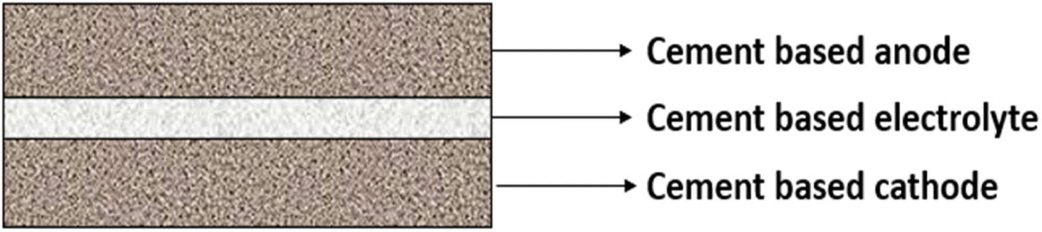 | ||
| Fig. 18 Schematic illustration of a battery, with cement as the continuous constituent in the cathode, electrolyte, and anode regions. | ||
The concept of a continuous cement-based battery has superior current capability and power density compared to other batteries utilizing set cement. However, its operation is limited to the wet state. Notably, the resistivity measurements reveal that, while the cement-based electrolyte exhibits higher resistivity with electronic contacts than the cement-based anode or cathode, it displays lower resistivity with ionic contacts. This suggests the prevalence of ionic conduction over electronic conduction in cement-based electrolytes. Nevertheless, the presence of some electronic conduction poses a hurdle to the further advancement of cement-based batteries. Addressing this challenge is critical for unlocking the full potential of cement-based battery technology and paving the way for broader applications in the future.
Magnesium phosphate cement (MPC), a rapidly setting cementitious substance, boasts superior eco-friendliness compared to that of PC, positioning it at the forefront of sustainable cement production practices in the future. Due to its amorphous structure and exceptional water-binding properties, polyacrylamide plays a dual role by enhancing ion conductivity in polymer solid electrolytes and bolstering the durability of concrete materials. The polymerized PAM within the MPC matrix can absorb a significant quantity of ions, thereby boosting the ionic conductivity of the composite electrolyte.138–140 Two distinct methods were employed for the fabrication of PAM/MPC composite electrolytes. The first method involved the in situ polymerization of monomers, referred to as IPSE (in situ polymerized solid electrolyte), while the second method, serving as the control group, entailed the direct addition of polymers, known as DASE (directly added solid electrolyte). The synthesis process for IPSE and DASE involves combining acrylamide (AM) or PAM with deionized water and then mixing the raw MPC materials. The resulting mixtures are then poured into test molds for evaluation. For IPSE, different concentrations of AM are used, while for DASE, different dosages of PAM are examined. The introduction of AM or PAM into the MPC pastes aims to enhance the structural and electrochemical properties of the resulting materials. The use of different concentrations of AM or dosages of PAM allows researchers to explore the influence of these additives on the performance of the final products. The careful curing of the materials for 28 days within a designated chamber is a critical step to ensure proper development of the structural and electrochemical properties. This approach provides valuable insights into improving the performance of these materials and provides a foundation for further advancements in electrolyte material synthesis for electrochemical applications141 (Fig. 19a and b).
 | ||
| Fig. 19 Two distinct methods were utilized for the fabrication of PAM/MPC composite electrolytes. (a) In situ Polymerized Solid Electrolyte (IPSE) and (b) Directly Added Solid Electrolyte (DASE). | ||
A layered cement–PVA hydrogel solid-state electrolyte (l-CPSSE) was designed for self-energy-storage buildings. l-CPSSE utilizes a cement matrix to provide structural support for the electrolyte, ensuring its mechanical strength and load-bearing capacity. The layered micropores are also filled with fast-ion-conducting hydrogels, creating ion diffusion pathways. The incorporation of PVA–KOH hydrogels not only enhances the electrochemical performance of cement but also facilitates cement hydration. The introduction of l-CPSSE, characterized by an exemplary compressive strength of 26.5 MPa and an ionic conductivity of 27.8 mS cm−1, represents a significant advancement in cement-based and hydrogel-based electrolytes. The successful assembly of all-cement-based solid-state energy storage devices demonstrated a notable full-cell specific capacity of 72.2 mF cm−2. Moreover, the practical application of a 5 × 5 cm2 building envelope model powered by 4 l-CPSSE-based full cells in series underscores the feasibility of cement-based supercapacitors in self-energy-storage buildings (Fig. 20).142 This innovative approach addresses the need for efficient energy storage solutions and demonstrates the potential for integrating sustainable and durable materials into the construction of energy-efficient infrastructure.
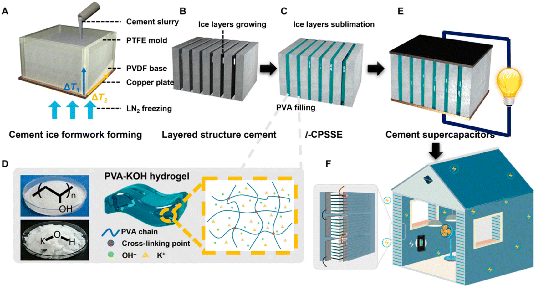 | ||
| Fig. 20 Schematic illustrations of the fabrication process of the layered cement–PVA solid-state electrolyte. (A) The placement of cement slurry in the mold with a bidirectional temperature gradient. (B) The oriented growth of ice sheets and the formation of cement lamellae. (C) The filling of PVA hydrogels between the cement lamellae after the ice sublimated. (D) Preparation and structure of PVA–KOH hydrogels. (E) Supercapacitors assembled based on l-CPSSE with electrodes. (F) Practical application illustrations of energy storage in building facilities. Reproduced from ref. 142 with permission from Elsevier, copyright 2024. | ||
Steel slag powder (SSP), a common byproduct of steel manufacturing, poses environmental challenges when improperly disposed.143 Given its composition is rich in calcium silicate compounds, particularly C2S, there is potential for utilizing SSP as a supplementary cementitious material (SCM) in cement-based products.144,145 The inclusion of SSP holds promise for enhancing the conductivity of cementitious materials due to the presence of conductive iron compounds.45,146,147 However, the limited reactivity of SSP has hindered its widespread adoption as an SCM.148
Kourounis et al.149 noted a decrease in the compressive strength of cement paste at 28 days when 15–45% SSP was incorporated, ranging from 12% to 28%. To address this issue, a proposed solution involves combining SSP with pozzolanic SCMs such as silica fume (SF) and fly ash (FA) to counterbalance the adverse effects of SSP.150 Research by Liu et al.151 highlights the significant improvement in the bond between calcium silicate hydrate (C–S–H) gel and SSP with the addition of SF, which positively impacts the pore structure of hardened paste and the strength of the concrete in later stages. Additionally, Peng et al.152 observed enhanced mechanical properties in concrete when utilizing both SSP and FA, attributing the improvements to the heightened hydration degree and refined microstructure facilitated by FA. Utilizing waste glass in powder form as a siliceous material with pozzolanic activity has proven to be a successful supplementary cementitious material in concrete, presenting an alternative avenue for recycling glass waste that would otherwise be landfilled or stockpiled.153,154 He et al.155 demonstrated that glass powder (GP) effectively enhances the microstructure of concrete through its pozzolanic reactivity and microfilling effect. The synergistic benefits of simultaneously incorporating SSP and GP have been substantiated by the compensatory role of GP in mitigating the workability and mechanical property losses associated with SSP (Fig. 21).157
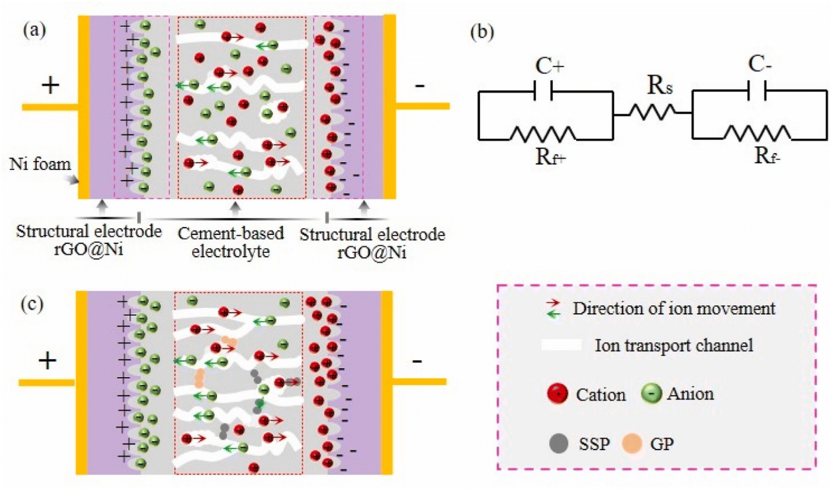 | ||
| Fig. 21 Schematic diagrams of (a) the SSCs with pure cement-based electrolyte paste, (b) equivalent circuit model, and (c) the SSCs with the cement-based electrolyte pastes containing SSP and GP. Reproduced from ref. 156 with permission from Elsevier, copyright 2024. | ||
In a study by Zhan et al.,158 it was found that replacing 20% of the cement with SSP and 10% with GP resulted in a remarkable increase in the compressive strength of the concrete. Specifically, the concrete exhibited a 28.3% and 22.8% improvement in compressive strength at 28 days and 120 days, respectively, compared to plain concrete. Notably, the unique characteristic of this environment is an extremely low oxygen content, rendering the cathodic reaction incompatible with oxygen reduction under such conditions. The cathodic reaction involves the evolution of hydrogen on the surface of the steel. For the efficient functioning of this battery system, it is crucial that the generated hydrogen can disperse from the steel surface at a rate consistent with its production rate. Failure to achieve this balance would lead to the accumulation of hydrogen pressure at the interface of steel and cement. As the electrolyte is a solid, this pressure build-up could result in brittle electrolyte cracking, allowing hydrogen to permeate into the steel. The permeation of hydrogen into steel has the additional consequence of rendering the steel more brittle, potentially leading to the formation of cracks. Consequently, this battery system is best suited for operation under a low discharge current density. Despite this limitation, it is theoretically possible to determine a substantial absolute current by employing a large surface area for the battery system. Such a significant surface area is necessary to facilitate a reasonable ion current flow through the electrolyte.159
In summary, concrete-based electrolytes consisting of different materials, including cement, polyvinyl alcohol, and polyacrylamide, doped with substances such as KOH and LiOTf enhance the specific capacitance of these structural supercapacitors while maintaining the crucial structural integrity of the materials. Furthermore, the focus on eco-friendly alternatives such as magnesium phosphate cement and the use of polyacrylamide to enhance ion conductivity represents a commitment to sustainable cement production practices, helping in a new era of construction technology. Concrete-based electrolytes represent a significant advancement in the domain of energy storage technologies, offering not only enhanced performance but also notable environmental benefits. Their utilization holds the potential to revolutionize sustainability in construction practices and reduce the carbon footprint associated with traditional energy storage solutions. Integrating concrete-based electrolytes into energy storage devices results in a notable reduction in the reliance on materials with larger carbon footprints. The incorporation of concrete-based electrolytes in energy storage systems promotes circularity in construction practices. This circular economy model emphasizes reusing waste materials and reducing overall environmental impact. Concrete, a material that can be recycled and repurposed, aligns with sustainability and resource efficiency principles.
The key parameters for concrete-based electrolytes include the use of Na2SO4 for better performance, the challenge of ensuring long-term durability, and the innovative creation of concrete electrolytes with high capacitance and structural strength. The electrolyte plays a pivotal role in cement-based energy storage systems, serving as the interface between structural functionality and electrical conductivity. Notably, it must withstand load-bearing demands while exhibiting high areal capacitance and facilitating ion flow over a large surface area to enhance energy storage capabilities. An intriguing aspect pertains to the interaction of polymers within the concrete, aiming to reconcile structural integrity with enhanced electrical performance, paving the way for a new era of multifunctional construction materials. These key parameters collectively transform traditional construction materials into an arena for pioneering technology and promising resilient, intelligent, and energy-efficient infrastructure.
Table 4 reveals that polyethylene oxide + cement with 5% LiOTf demonstrates superior performance to the other electrolytes in terms of energy density and compressive strength. This electrolyte exhibits an impressive energy density, indicating its ability to store significant energy per unit area. Additionally, it boasts a high compressive strength, highlighting its structural integrity and suitability for load-bearing applications. These properties indicate that polyethylene oxide + cement with 5% LiOTf is the most suitable electrolyte among those listed. In comparison, other electrolytes, such as cement, magnesium phosphate cement, the cement/PVA–KOH composite, hardened cement paste, and PAA + Portland, demonstrate varying levels of energy density and compressive strength. For example, the PAA + Portland electrolyte exhibits compressive strength, indicating its suitability for structural applications. On the other hand, PAA + Portland with 5% LiOTf demonstrated a moderate energy density and compressive strength, suggesting its potential for energy storage and construction applications. However, none of the other electrolytes in the table match the balanced combination of high energy density and robust compressive strength offered by the polyethylene oxide + cement with 5% LiOTf, making it a well-rounded option for advanced energy storage systems with a focus on both energy storage and structural applications.
| Material | Electrolyte | Specific/areal capacitance | Energy density | Compressive strength (MPa) | Reference |
|---|---|---|---|---|---|
| Cement | 2 wt% Na2SO4 | 35.18 mF cm−2 | — | 32.67 | 45 |
| Magnesium phosphate cement | 2 M KOH | 46.38 F g−1 | — | 24.59 | 134 |
| Cement/PVA–KOH composite | KOH | 9.74 mF cm−2 | 0.13 mW h cm−2 | — | 112 |
| Hardened cement paste | 1 M KOH | 10 F g−1 | — | 9.85 | 96 |
| Polyethylene oxide cement | 5% KOH | 439.35 mF cm−2 | 0.2 mW h cm−2 | 22.29 | 123 |
| Polyethylene oxide + cement | 5% LiOTf | 407.07 mF cm−2 | 0.74 mW h cm−2 | 28.26 | 123 |
| Polyacrylic acid (PAA) + Portland | KOH | 51.5 mF cm−2 | — | 28.5 | 111 |
| Polyacrylic acid (PAA) + Portland | 5% LiOTf | 314.9 mF cm−2 | 0.65 mW h cm−2 | 23.65 | 59 |
As we referred to current trends using Scopus-736-Analyze-Year with our query (TITLE-ABS-KEY (cement-based energy storage)), we found 736 articles from the year 2000 related to cement-based energy storage. However, only 10 to 20 articles studied electrochemical theory-based concrete/cement-based energy storage devices, which were recently discussed within the last 3 years. Hence, revealing a large scope for all-solid-state energy storage devices wherein challenges such as brittleness, curing time, conducting elements, hybrid structures (meso and microporous), wettability, elemental compositions, additives, fillers, etc., need to be addressed.
Conclusions, challenges, and future perspective
Concrete-based energy storage devices face several challenges that need to be addressed for their successful implementation and commercialization. Both concrete-based batteries and supercapacitors currently face limitations in energy density compared to conventional lithium-ion batteries. While advancements have been made, such as the development of carbon–cement supercapacitors that utilize materials like carbon black to enhance conductivity, achieving competitive energy densities remains a significant hurdle. The energy storage capacity of concrete-based systems needs to be improved to make them viable alternatives for applications requiring substantial energy storage. The integration of conductive materials, such as carbon black and carbon fibers, into concrete formulations can increase production costs. Although concrete itself is inexpensive, the need for these additional materials may raise the overall cost of concrete-based energy storage devices. Balancing cost-effectiveness with performance is crucial for widespread adoption. Integrating concrete-based energy storage solutions into existing buildings and infrastructure poses logistical challenges. The rebuilding of structures to incorporate energy storage capabilities requires careful design and planning. Additionally, the transition from traditional energy storage methods to concrete-based systems necessitates changes in regulatory frameworks and standards to accommodate these new technologies. Although there is growing interest in concrete-based energy storage technologies, research is still in its early stages. More extensive studies are required to explore the full potential of these systems, including their scalability, efficiency, and integration with renewable energy sources. Continued investment in research and development is vital to overcoming the challenges and unlocking the benefits of concrete-based energy storage.In the future, the integration of energy storage devices with concrete-based materials represents a realm ripe for innovation. Future research could focus on enhancing the mechanical strength, ionic conductivity, and electrode compatibility to merge structural and energy functionalities seamlessly. The interplay between porosity, compressive strength, and energy storage capacity offers a promising avenue for exploration, paving the way for multifunctional and resilient infrastructure solutions. Additionally, the incorporation of innovative additives into concrete-based electrolytes and electrodes holds vast potential for enhancing energy performance and advancing the efficiency of structural supercapacitors. By leveraging alkali metal salts in Portland cement electrolytes, researchers have unlocked a new realm of possibilities, where the relationship between porosity, compressive strength, and energy storage properties has catalyzed the creation of highly functional electrolytes. This transformative synergy between construction materials and energy technologies within concrete electrodes offers strength and adaptability and paves the way for sustainable and effective infrastructure solutions.
In conclusion, this comprehensive review sheds light on the evolving landscape of energy storage technologies. The imperative need for efficient energy storage solutions in the face of diminishing fossil fuel reserves and escalating environmental concerns has steered the trajectory of research toward innovative structural energy storage devices. Concrete-based energy storage devices, characterized by their multifunctional attributes and transformative potential, represent a pivotal convergence of material science, energy technology, and sustainable construction practices. This paper provides details on how the use of concrete-based electrolytes and electrodes provides distinct advantages in terms of electrical properties, mechanical strength, and energy storage capacity.
Data availability
No data has been used in this article.Conflicts of interest
There are no conflicts to declare.Acknowledgements
During the preparation of this work, the authors used ChatGPT and Grammarly to improve the language and readability. After using this tool/service, the authors reviewed and edited the content as needed and takes full responsibility for the content of the publication.References
- V. Khare, S. Nema and P. Baredar, Renewable Sustainable Energy Rev., 2016, 58, 23–33 CrossRef.
- J. Benedek, T. T. Sebestyén and B. Bartók, Renewable Sustainable Energy Rev., 2018, 90, 516–535 CrossRef.
- K. Y. Chan, B. Jia, H. Lin, N. Hameed, J. H. Lee and K. T. Lau, Compos. Struct., 2018, 188, 126–142 CrossRef.
- Y. Huang, M. Zhu, Y. Huang, Z. Pei, H. Li, Z. Wang, Q. Xue and C. Zhi, Adv. Mater., 2016, 28, 8344–8364 CrossRef CAS PubMed.
- N. Shirshova, H. Qian, M. S. P. Shaffer, J. H. G. Steinke, E. S. Greenhalgh, P. T. Curtis, A. Kucernak and A. Bismarck, Composites, Part A, 2013, 46, 96–107 CrossRef CAS.
- N. Chanut, D. Stefaniuk, J. C. Weaver, Y. Zhu, Y. Shao-Horn, A. Masic and F.-J. Ulm, Proc. Natl. Acad. Sci. U. S. A., 2023, 120, e2304318120 CrossRef CAS PubMed.
- P. K. Mehta and P. Monteiro, Concrete: Microstructure, Properties, and Materials, McGraw-Hill, 4th edn, 2014 Search PubMed.
- B. Han, S. Ding and X. Yu, Measurement, 2015, 59, 110–128 CrossRef.
- S. Ding, S. Dong, A. Ashour and B. Han, J. Appl. Phys., 2019, 126, 241101 CrossRef.
- R. B. Choudhary, S. Ansari and B. Purty, J. Energy Storage, 2020, 29, 101302 CrossRef.
- B. Pal, S. Yang, S. Ramesh, V. Thangadurai and R. Jose, Nanoscale Adv., 2019, 1, 3807–3835 RSC.
- R. Kötz and M. Carlen, Electrochim. Acta, 2000, 45, 2483–2498 CrossRef.
- Z. S. Iro, C. Subramani and S. S. Dash, Int. J. Electrochem. Sci., 2016, 11, 10628–10643 CrossRef CAS.
- M. Y. Ho, P. S. Khiew, D. Isa, T. K. Tan, W. S. Chiu and C. H. Chia, Nano, 2014, 09, 1430002 CrossRef CAS.
- A. González, E. Goikolea, J. A. Barrena and R. Mysyk, Renewable Sustainable Energy Rev., 2016, 58, 1189–1206 CrossRef.
- C. Largeot, C. Portet, J. Chmiola, P.-L. Taberna, Y. Gogotsi and P. Simon, J. Am. Chem. Soc., 2008, 130, 2730–2731 CrossRef CAS PubMed.
- P. Lu, D. Xue, H. Yang and Y. Liu, Int. J. Smart Nano Mater., 2013, 4, 2–26 CrossRef CAS.
- S. M. Halper and J. C. Ellenbogen, Supercapacitors: A Brief Overview, 2006 Search PubMed.
- Y. Huang, C.-F. Yan, C.-Q. Guo, Z.-X. Lu, Y. Shi and Z.-D. Wang, Int. J. Hydrogen Energy, 2017, 42, 4007–4016 CrossRef CAS.
- A. Muzaffar, M. B. Ahamed, K. Deshmukh and J. Thirumalai, Renewable Sustainable Energy Rev., 2019, 101, 123–145 CrossRef CAS.
- J. Yan, Z. Fan, W. Sun, G. Ning, T. Wei, Q. Zhang, R. Zhang, L. Zhi and F. Wei, Adv. Funct. Mater., 2012, 22, 2632–2641 CrossRef CAS.
- A. Balducci, R. Dugas, P. L. Taberna, P. Simon, D. Plée, M. Mastragostino and S. Passerini, J. Power Sources, 2007, 165, 922–927 CrossRef CAS.
- A. G. Pandolfo and A. F. Hollenkamp, J. Power Sources, 2006, 157, 11–27 CrossRef CAS.
- S. I. Wong, J. Sunarso, B. T. Wong, H. Lin, A. Yu and B. Jia, J. Power Sources, 2018, 396, 182–206 CrossRef CAS.
- T. C. Mendes, F. Zhou, A. J. Barlow, M. Forsyth, P. C. Howlett and D. R. MacFarlane, Sustainable Energy Fuels, 2018, 2, 763–771 RSC.
- H. D. Abruña, Y. Kiya and J. C. Henderson, Phys. Today, 2008, 61, 43–47 CrossRef.
- K. Hung, C. Masarapu, T. Ko and B. Wei, J. Power Sources, 2009, 193, 944–949 CrossRef CAS.
- S.-H. Bae, C. Jeon, S. Oh, C.-G. Kim, M. Seo and I.-K. Oh, Carbon, 2018, 139, 10–20 CrossRef CAS.
- S. W. Zhang, B. S. Yin, X. X. Liu, D. M. Gu, H. Gong and Z. B. Wang, Nano Energy, 2019, 59, 41–49 CrossRef CAS.
- N. L. Wulan Septiani, Y. V. Kaneti, K. B. Fathoni, J. Wang, Y. Ide, B. Yuliarto, Nugraha, H. K. Dipojono, A. K. Nanjundan, D. Golberg, Y. Bando and Y. Yamauchi, Nano Energy, 2020, 67, 104270 CrossRef CAS.
- Y. Li, J. Henzie, T. Park, J. Wang, C. Young, H. Xie, J. W. Yi, J. Li, M. Kim, J. Kim, Y. Yamauchi and J. Na, Bull. Chem. Soc. Jpn., 2020, 93, 176–181 CrossRef CAS.
- A. González, E. Goikolea, J. A. Barrena and R. Mysyk, Renewable Sustainable Energy Rev., 2016, 58, 1189–1206 CrossRef.
- D. P. Dubal, N. R. Chodankar, D. H. Kim and P. Gomez-Romero, Chem. Soc. Rev., 2018, 47, 2065–2129 RSC.
- S. Shaheen Shah, S. M. Abu Nayem, N. Sultana, A. J. Saleh Ahammad and M. Abdul Aziz, ChemSusChem, 2022, 15, e202101282 CrossRef CAS PubMed.
- T. Shang, Y. Xu, P. Li, J. Han, Z. Wu, Y. Tao and Q.-H. Yang, Nano Energy, 2020, 70, 104531 CrossRef CAS.
- J. M. Miller, B. Dunn, T. D. Tran and R. W. Pekala, J. Electrochem. Soc., 1997, 144, L309–L311 CrossRef CAS.
- Z. Bekzhanova, S. A. Memon and J. R. Kim, Nanomaterials, 2021, 11, 2355 CrossRef CAS PubMed.
- S. Barbhuiya, F. Kanavaris, B. B. Das and M. Idrees, J. Build. Eng., 2024, 86, 108861 CrossRef.
- E. P. Sumukh, B. B. Das and S. Barbhuiya, Int. J. Civ. Eng., 2024, 22, 1137–1158 CrossRef.
- J. Lopez, Y. Sun, D. G. Mackanic, M. Lee, A. M. Foudeh, M. S. Song, Y. Cui and Z. Bao, Adv. Mater., 2018, 30, 1804142 CrossRef PubMed.
- E. Frackowiak, M. Meller, J. Menzel, D. Gastol and K. Fic, Faraday Discuss., 2014, 172, 179–198 RSC.
- B. Akinwolemiwa, C. Peng and G. Z. Chen, J. Electrochem. Soc., 2015, 162, A5054–A5059 CrossRef CAS.
- S. Domanskyi, D. T. Gentekos, V. Privman and B. P. Fors, Polym. Chem., 2020, 11, 326–336 RSC.
- Y. Xing, Y.-B. He, B. Li, X. Chu, H. Chen, J. Ma, H. Du and F. Kang, Electrochim. Acta, 2013, 109, 512–518 CrossRef CAS.
- C. Fang and D. Zhang, Constr. Build. Mater., 2021, 285, 122897 CrossRef CAS.
- J. Xu and D. Zhang, Electrochim. Acta, 2017, 224, 105–112 CrossRef CAS.
- S. Hampton, T. Fawcett, J. Rosenow, C. Michaelis and R. Mayne, Joule, 2021, 5, 285–289 CrossRef.
- Y. Gogotsi and P. Simon, Science, 2011, 334, 917–918 CrossRef CAS PubMed.
- J. W. Fergus, J. Power Sources, 2010, 195, 4554–4569 CrossRef CAS.
- J. F. Snyder, E. D. Wetzel and C. M. Watson, Polymer, 2009, 50, 4906–4916 CrossRef CAS.
- A. M. Stephan, Eur. Polym. J., 2006, 42, 21–42 CrossRef.
- J. L. Provis, Cem. Concr. Res., 2018, 114, 40–48 CrossRef CAS.
- M. A. Rafiee, T. N. Narayanan, D. P. Hashim, N. Sakhavand, R. Shahsavari, R. Vajtai and P. M. Ajayan, Adv. Funct. Mater., 2013, 23, 5624–5630 CrossRef CAS.
- Q. Meng and D. D. L. Chung, Cem. Concr. Compos., 2010, 32, 829–839 CrossRef CAS.
- A. Sundaramoorthi and P. Thangaraj, J. Eng. Appl. Sci., 2023, 70, 39 CrossRef CAS.
- A. Byrne, S. Barry, N. Holmes and B. Norton, Adv. Mater. Sci. Eng., 2017, 2017, 1–14 CrossRef.
- M. K. Aslam, H. Wang, S. Chen, Q. Li and J. Duan, Mater. Today Energy, 2023, 31, 101196 CrossRef CAS.
- L. Wu, L. Li, M. Fan, P. Tang, S. Yang, L. Pan, H. Wang and Y. Bin, Composites, Part A, 2020, 138, 106050 CrossRef CAS.
- C. Fang and D. Zhang, Chem. Eng. J., 2021, 426, 130793 CrossRef CAS.
- J. Lin, Q. Li, S. Lu, X. Chen and K. M. Liew, J. Hazard. Mater., 2020, 389, 121946 CrossRef CAS PubMed.
- E.-L. Bai, J.-Y. Xu, S. Lu, K.-X. Lin and Y.-M. Zhang, RSC Adv., 2018, 8, 14454–14461 RSC.
- M. Nagao, K. Kobayashi, Y. Jin, I. Maruyama and T. Hibino, J. Mater. Chem. A, 2020, 8, 15157–15166 RSC.
- S. I. Basha, S. S. Shah, S. Ahmad, M. Maslehuddin, M. M. Al-Zahrani and M. A. Aziz, Chem. Rec., 2022, 22, e202200134 CrossRef CAS PubMed.
- W. Li, W. Dong, A. Castel and D. Sheng, J. Proc. R. Soc. N. S. W., 2021, 154, 24–32 Search PubMed.
- Y. Sun, S. Ding, B. Xia, J. Duan, M. Antonietti and S. Chen, Angew. Chem., Int. Ed., 2022, 61, e202115198 CrossRef CAS PubMed.
- X. Luo, J. Wang, M. Dooner and J. Clarke, Appl. Energy, 2015, 137, 511–536 CrossRef.
- Q. Liao, B. Sun, Y. Liu, J. Sun and G. Zhou, Int. J. Energy Res., 2016, 40, 241–247 CrossRef.
- N. Kawakami, Y. Iijima, M. Fukuhara, M. Bando, Y. Sakanaka, K. Ogawa and T. Matsuda, in 2010 IEEE International Symposium on Industrial Electronics, IEEE, 2010, pp. 2371–2376 Search PubMed.
- N. Tokuda, T. Kanno, T. Hara, T. Shigematsu, Y. Tsutsui, A. Ikeuchi, T. Itou and T. Kumamoto, Development of a Redox Flow Battery System, SEI Technical Review, 2000, vol. 50, pp. 88–93 Search PubMed.
- C. Ponce de León, A. Frías-Ferrer, J. González-García, D. A. Szánto and F. C. Walsh, J. Power Sources, 2006, 160, 716–732 CrossRef.
- B. Diouf and R. Pode, Renewable Energy, 2015, 76, 375–380 CrossRef.
- L. Yin, S. Liu, D. Yin, K. Du, J. Yan, C. K. Armwood-Gordon and L. Li, J. Energy Storage, 2024, 93, 112181 CrossRef.
- B. Chen, K. Wu and W. Yao, Cem. Concr. Compos., 2004, 26, 291–297 CrossRef CAS.
- S. Wen and D. D. L. Chung, Carbon, 2007, 45, 263–267 CrossRef CAS.
- B. K. Kim, S. Sy, A. Yu and J. Zhang, in Handbook of Clean Energy Systems, Wiley, 2015, pp. 1–25 Search PubMed.
- L. Yu, L. P. Wang, H. Liao, J. Wang, Z. Feng, O. Lev, J. S. C. Loo, M. T. Sougrati and Z. J. Xu, Small, 2018, 14, 1703338 CrossRef PubMed.
- Y. Ma, Energy Environ. Mater., 2018, 1, 148–173 CrossRef CAS.
- M. S. Palagonia, C. Erinmwingbovo, D. Brogioli and F. La Mantia, J. Electroanal. Chem., 2019, 847, 113170 CrossRef CAS.
- N. Elgrishi, K. J. Rountree, B. D. McCarthy, E. S. Rountree, T. T. Eisenhart and J. L. Dempsey, J. Chem. Educ., 2018, 95, 197–206 CrossRef CAS.
- J. J. Van Benschoten, J. Y. Lewis, W. R. Heineman, D. A. Roston and P. T. Kissinger, J. Chem. Educ., 1983, 60, 772 CrossRef CAS.
- G. A. Mabbott, J. Chem. Educ., 1983, 60, 697 CrossRef CAS.
- E. M. Espinoza, J. A. Clark, J. Soliman, J. B. Derr, M. Morales and V. I. Vullev, J. Electrochem. Soc., 2019, 166, H3175–H3187 CrossRef CAS.
- W. Lu, R. Hartman, L. Qu and L. Dai, J. Phys. Chem. Lett., 2011, 2, 655–660 CrossRef CAS.
- M. D. Stoller and R. S. Ruoff, Energy Environ. Sci., 2010, 3, 1294 RSC.
- B. K. Kim, V. Chabot and A. Yu, Electrochim. Acta, 2013, 109, 370–380 CrossRef CAS.
- Y. Jiang and J. Liu, Energy Environ. Mater., 2019, 2, 30–37 CrossRef.
- S. Sharma and P. Chand, Results Chem., 2023, 5, 100885 CrossRef CAS.
- H. Wang and L. Pilon, Electrochim. Acta, 2012, 76, 529–531 CrossRef CAS.
- J. C. Dixon, The Fourier Transform, in Suspension Geometry and Computation, Wiley, 2009, pp. 395–402 Search PubMed.
- B. A. Mei, O. Munteshari, J. Lau, B. Dunn and L. Pilon, J. Phys. Chem. C, 2018, 122, 194–206 CrossRef CAS.
- V. Sedlakova, J. Sikula, J. Majzner, P. Sedlak, T. Kuparowitz, B. Buergler and P. Vasina, J. Power Sources, 2015, 286, 58–65 CrossRef CAS.
- E. Q. Zhang and L. Tang, Buildings, 2021, 11, 103 CrossRef.
- N. Holmes, A. Byrne, B. Norton, P. Brian Norton and S. Servicesnews, Journal of Sustainable Design and Applied Research, 2015 DOI:10.21427/D7H32N.
- A. D'Alessandro, M. Rallini, F. Ubertini, A. L. Materazzi and J. M. Kenny, Cem. Concr. Compos., 2016, 65, 200–213 CrossRef.
- S. Wen and D. D. L. Chung, Cem. Concr. Res., 2000, 30, 661–664 CrossRef CAS.
- J. Zhang, J. Xu and D. Zhang, J. Electrochem. Soc., 2016, 163, E83–E87 CrossRef CAS.
- Y. Yuan, H. Li, S. Han, L. Hu and G. Xu, Talanta, 2011, 84, 49–52 CrossRef CAS PubMed.
- D. Yan, J. Mao, R. Gao, W. Wang, S. Wang, S. Ruan, H. Qian, F. Mu, S. Chen and Y. Liu, J. Energy Storage, 2024, 96, 112717 CrossRef.
- M. Bagge-Hansen, B. C. Wood, T. Ogitsu, T. M. Willey, I. C. Tran, A. Wittstock, M. M. Biener, M. D. Merrill, M. A. Worsley, M. Otani, C.-H. Chuang, D. Prendergast, J. Guo, T. F. Baumann, T. van Buuren, J. Biener and J. R. I. Lee, Adv. Mater., 2015, 27, 1512–1518 CrossRef CAS PubMed.
- S. Lv, Y. Ma, C. Qiu, T. Sun, J. Liu and Q. Zhou, Constr. Build. Mater., 2013, 49, 121–127 CrossRef CAS.
- S. Lv, J. Liu, T. Sun, Y. Ma and Q. Zhou, Constr. Build. Mater., 2014, 64, 231–239 CrossRef.
- K. Gong, Z. Pan, A. H. Korayem, L. Qiu, D. Li, F. Collins, C. M. Wang and W. H. Duan, J. Mater. Civ. Eng., 2014, 27, A4014010 CrossRef.
- Q. Meng and D. D. L. Chung, Cem. Concr. Compos., 2010, 32, 829–839 CrossRef CAS.
- J. J. Thomas, H. M. Jennings and A. J. Allen, Nat. Mater., 2007, 6, 311–316 CrossRef PubMed.
- L. Li, J. Zhang, Z. Peng, Y. Li, C. Gao, Y. Ji, R. Ye, N. D. Kim, Q. Zhong, Y. Yang, H. Fei, G. Ruan and J. M. Tour, Adv. Mater., 2016, 28, 838–845 CrossRef CAS PubMed.
- S. Aderyani, P. Flouda, S. A. Shah, M. J. Green, J. L. Lutkenhaus and H. Ardebili, Electrochim. Acta, 2021, 390, 138822 CrossRef CAS.
- X. Xu, J. Tang, H. Qian, S. Hou, Y. Bando, M. S. A. Hossain, L. Pan and Y. Yamauchi, ACS Appl. Mater. Interfaces, 2017, 9, 38737–38744 CrossRef CAS PubMed.
- M. Saafi, A. Gullane, B. Huang, H. Sadeghi, J. Ye and F. Sadeghi, Compos. Struct., 2018, 201, 766–778 CrossRef.
- J. Tao, N. Liu, L. Li, J. Su and Y. Gao, Nanoscale, 2014, 6, 2922 RSC.
- B. Tripathi, Mater. Today: Proc., 2021, 42, 1689–1691 CAS.
- C. Fang and D. Zhang, J. Mater. Chem. A, 2020, 8, 12586–12593 RSC.
- C. Xu and D. Zhang, J. Compos. Mater., 2021, 55, 1359–1369 CrossRef CAS.
- Z. Lu, S. Li, J. Xie, Q. Huang, B. Zhang, P. Huang, J. Li and L. Li, Constr. Build. Mater., 2022, 326, 126979 CrossRef CAS.
- Y. Chang, Y. Wang, M. Wang, Z. Zhou and J. Ou, Constr. Build. Mater., 2021, 307, 124878 CrossRef CAS.
- C. Fang and D. Zhang, Mater. Des., 2020, 186, 108322 CrossRef CAS.
- N. Shirshova, A. Bismarck, S. Carreyette, Q. P. V. Fontana, E. S. Greenhalgh, P. Jacobsson, P. Johansson, M. J. Marczewski, G. Kalinka, A. R. J. Kucernak, J. Scheers, M. S. P. Shaffer, J. H. G. Steinke and M. Wienrich, J. Mater. Chem. A, 2013, 1, 15300 RSC.
- S. Leijonmarck, T. Carlson, G. Lindbergh, L. E. Asp, H. Maples and A. Bismarck, Compos. Sci. Technol., 2013, 89, 149–157 CrossRef CAS.
- T. Adam, G. Liao, J. Petersen, S. Geier, B. Finke, P. Wierach, A. Kwade and M. Wiedemann, Energies, 2018, 11, 335 CrossRef.
- C. Zhou, Q. Wang and C. Zhang, Materials, 2022, 15, 2459 CrossRef CAS PubMed.
- Z. He, P. Zhan, S. Du, B. Liu and W. Yuan, Composites, Part B, 2019, 166, 13–20 CrossRef CAS.
- P. Zhan, X. Zhang, Z. He, J. Shi, O. Gencel, N. T. Hai Yen and G. Wang, J. Cleaner Prod., 2022, 341, 130892 CrossRef CAS.
- P. Zhan, J. Xu, J. Wang and C. Jiang, Constr. Build. Mater., 2021, 307, 125082 CrossRef CAS.
- C. Fang and D. Zhang, Electrochim. Acta, 2022, 401, 139491 CrossRef CAS.
- M. Liu, W. W. Tjiu, J. Pan, C. Zhang, W. Gao and T. Liu, Nanoscale, 2014, 6, 4233 RSC.
- J. Wang, P. Zhan and D. Zhang, Cem. Concr. Compos., 2023, 138, 104987 CrossRef CAS.
- N. Yoshida, Y. Yamada, S. Nishimura, Y. Oba, M. Ohnuma and A. Yamada, J. Phys. Chem. C, 2013, 117, 12003–12009 CrossRef CAS.
- T. Nguyen and M. F. Montemor, Appl. Surf. Sci., 2017, 422, 492–497 CrossRef CAS.
- M. Drábik, S. C. Mojumdar and R. C. T. Slade, Prospects of novel macro defect free cements for the new millennium, Ceramics-Silikaty, 2002, 46, 68–73 Search PubMed.
- Y. Lijuan, W. Peiming and W. Ru, Bull. Chin. Ceram. Soc., 2011, 30, 818–821 Search PubMed.
- E. Sakai and J. Sugita, Cem. Concr. Res., 1995, 25, 127–135 CrossRef CAS.
- A. Amore Bonapasta, F. Buda and P. Colombet, Chem. Mater., 2000, 12, 738–743 CrossRef.
- J. Wang and D. Zhang, Mater. Chem. Phys., 2022, 277, 125488 CrossRef CAS.
- X. Liu, C. Shi, C. Zhai, M. Cheng, Q. Liu and G. Wang, ACS Appl. Mater. Interfaces, 2016, 8, 4585–4591 CrossRef CAS PubMed.
- W. Ma and D. Zhang, J. Compos. Mater., 2019, 53, 719–730 CrossRef CAS.
- N. Shi and D. Zhang, Electrochim. Acta, 2021, 391, 138998 CrossRef CAS.
- Q. Yuan, Z. Xie, H. Yao, T. Huang and M. Fan, J. Build. Eng., 2022, 56, 104763 CrossRef.
- Q. Meng and D. D. L. Chung, Cem. Concr. Compos., 2010, 32, 829–839 CrossRef CAS.
- S. A. Walling and J. L. Provis, Chem. Rev., 2016, 116, 4170–4204 CrossRef CAS PubMed.
- A. Virya and K. Lian, Electrochem. Commun., 2017, 81, 52–55 CrossRef CAS.
- Z. Sun and Q. Xu, Mater. Sci. Eng., A, 2008, 490, 181–192 CrossRef.
- P. Jiao, C. Fang and D. Zhang, J. Energy Storage, 2022, 55, 105416 CrossRef.
- W. Lin, J. Xing, Y. Zhou, L. Pan, L. Yang, Y. Zhang, X. X. Liu, C. Xiong, W. Li and Z. Sun, Research, 2024, 7, 0379 CrossRef CAS PubMed.
- S. Zhang, Z. Ghouleh, A. Mucci, O. Bahn, R. Provençal and Y. Shao, J. Cleaner Prod., 2022, 342, 130948 CrossRef CAS.
- C. Shi, J. Mater. Civ. Eng., 2004, 16, 230–236 CrossRef CAS.
- J. Zhao, P. Yan and D. Wang, J. Cleaner Prod., 2017, 156, 50–61 CrossRef CAS.
- Z. Pan, J. Zhou, X. Jiang, Y. Xu, R. Jin, J. Ma, Y. Zhuang, Z. Diao, S. Zhang, Q. Si and W. Chen, Constr. Build. Mater., 2019, 200, 570–577 CrossRef.
- Q. Wang, P. Yan, J. Yang and B. Zhang, Constr. Build. Mater., 2013, 47, 1414–1420 CrossRef.
- Y. Jiang, T.-C. Ling, C. Shi and S.-Y. Pan, Resour., Conserv. Recycl., 2018, 136, 187–197 CrossRef CAS.
- S. Kourounis, S. Tsivilis, P. E. Tsakiridis, G. D. Papadimitriou and Z. Tsibouki, Cem. Concr. Res., 2007, 37, 815–822 CrossRef CAS.
- C. Shi and J. Qian, Resour., Conserv. Recycl., 2000, 29, 195–207 CrossRef.
- J. Liu and D. Wang, Powder Technol., 2017, 320, 230–238 CrossRef CAS.
- Y. Z. Peng, K. Chen and S. G. Hu, Adv. Mater. Res., 2011, 194–196, 956–960 CAS.
- Y. Du, W. Yang, Y. Ge, S. Wang and P. Liu, J. Cleaner Prod., 2021, 287, 125018 CrossRef CAS.
- M. Mirzahosseini and K. A. Riding, Cem. Concr. Compos., 2015, 56, 95–105 CrossRef CAS.
- Z. He, P. Zhan, S. Du, B. Liu and W. Yuan, Composites, Part B, 2019, 166, 13–20 CrossRef CAS.
- P. Zhan, J. Xu, J. Wang, J. Zuo and Z. He, Cem. Concr. Compos., 2023, 137, 104924 CrossRef CAS.
- Y. C. Lim, Y.-J. Shih, K.-C. Tsai, W.-D. Yang, C.-W. Chen and C.-D. Dong, J. Environ. Manage., 2020, 270, 110869 CrossRef CAS PubMed.
- P. Zhan, X. Zhang, Z. He, J. Shi, O. Gencel, N. T. Hai Yen and G. Wang, J. Cleaner Prod., 2022, 341, 130892 CrossRef CAS.
- G. T. Burstein and E. I. Speckert, ECS Trans., 2008, 3, 13–20 CrossRef.
| This journal is © The Royal Society of Chemistry 2024 |