 Open Access Article
Creative Commons Attribution 3.0 Unported Licence
A novel ultra-high vacuum diffusion setup to study Knudsen diffusion
Maria
Mourkou
 a,
Haiyue
Yu
a,
Sander
Baltussen
b,
Nicholas
Snead
a,
Nidhi
Kapil
a,
Haiyue
Yu
a,
Sander
Baltussen
b,
Nicholas
Snead
a,
Nidhi
Kapil
 a and
Marc-Olivier
Coppens
 *a
*a
aCentre for Nature Inspired Engineering & Department of Chemical Engineering, University College London, Torrington Place, London WC1E 7JE, UK. E-mail: m.coppens@ucl.ac.uk
bIndependent Researcher, Nijmegen, NL, The Netherlands
First published on 3rd September 2024
Abstract
A new experimental technique has been developed for studies of transport diffusion in the Knudsen regime. At atmospheric pressure, the Knudsen regime is prevalent for gas diffusion in mesoporous materials. A unique, specially designed Ultra-High Vacuum Diffusion Setup has been built that allows the generation of high Knudsen numbers at macroscopic scales by employing ultra-high vacuum conditions. The diffusion channel of the setup can, therefore, act as a magnified nanopore model to help study the impact of different pore geometries on Knudsen diffusion. Pore channels with varying pore length, pore cross-sectional shape, and pore diameter were realised and tested with this setup. The results obtained using this experimental technique can be compared with analytical and computational results to gain insight into diffusion in nanoporous materials.
Introduction
Nanoporous materials are a vast category of materials with pore sizes smaller than 100 nm that find applications in catalysis, sorption, membrane separation and drug delivery.1 Diffusion in nanoporous materials has been the subject of extensive studies over the years.2–9 Amongst these materials, a notably challenging category comprises of amorphous mesoporous materials (pore sizes between 2 and 50 nm), because their structure is disordered and their pore space complex.10 A major difficulty in the characterization of these materials lies in their heterogeneities, both chemical and geometrical, which can be difficult to isolate in experimental studies.11 Pore network topology, surface roughness of single pores, and flexibility of the pore walls are some of the geometrical heterogeneities that can be encountered, while, for example, inhomogeneous distribution of adsorption or catalytically active sites over the surface of the pore walls can be listed among the chemical heterogeneities.12,13 These heterogeneities are responsible for changes in the mobility of the guest molecules and accessibility to active sites, from confinement effects in single pores, and changes in adsorbate binding energies or the stability of reaction intermediates along the catalyst surface, to changes in pore network connectivity. All these effects can impact the diffusion coefficients, adsorption isotherms, effective reaction rates, and, thus, the observed catalytic selectivity and reactant conversion.14 Therefore, these heterogeneities are important to be identified and considered in simulations, catalyst design, and reactor design and modelling.The effect of geometric attributes of single pores or channels, including their length and shape, on rarefied gas flow, corresponding to Knudsen diffusion, has drawn much attention. Over the years, a wide array of geometries has been studied analytically and computationally, employing methods that include Monte Carlo simulations and continuum approaches. Davis15 developed a method to compute the molecular trajectories of test molecules inside short channels via Monte Carlo simulations to calculate the mass flow rate. This method was applied to various geometries, including a cylindrical pipe with a circular cross section, a cylindrical elbow, and other configurations, such as a cylindrical annulus and a cylinder with restrictions at both ends. Davis also performed a parametric study of the length-to-radius ratio (L/R) for all the aforementioned geometries. Varoutis et al.16 continued this computational work with a test system consisting of two reservoirs at both ends connected to a pipe with L/R ratios varying from 0 to 10 to calculate the flow rates for rarefied gas flow in vacuum systems, while Titarev17 extended their research to examine L/R ratios up to 50.
Whilst these studies were mainly carried out with vacuum technological applications in mind, it is not only the length of a single channel that can be significant, particularly when studying Knudsen diffusion in porous materials. Amorphous porous materials typically possess different pore sizes, pore structures, complex textural characteristics and irregular pore network connectivity, the impact of which on diffusion is usually described using parameters such as the porosity and tortuosity.13 Evans and Abbasi18,19 conducted Monte Carlo simulations within porous media represented as an assembly of randomly packed spheres, adopting Davis' approach of utilizing test molecules, to establish correlations between Knudsen diffusion, porosity and tortuosity. Nakano et al.20 continued this exploration by conducting Monte Carlo simulations in pore channels with straight, concave, and convex pore walls, concluding that the Knudsen diffusivity, as well as the number of collisions with the pore walls are greatly affected by the pore geometry, proving the importance of studying different pore geometries in the Knudsen regime. Burganos and Payatakes21 investigated pores with converging–diverging pore walls and stated that the effect of pore geometry and, more specifically, constrictions in a pore is far stronger than the effect of the pore length on the diffusivity, leading to a steeper decrease of the diffusivity as the relative size of the narrowing decreases. Another important finding in their work is that, although a constriction inside a pore can cause a decrease in the diffusivity, repeated periodic cavities in a pore channel could cause an increase in the diffusivity.
To provide experimental evidence for the influence of geometrical characteristics on Knudsen diffusivity, different approaches have been proposed. Davis, Levenson, and Milleron22 measured the flow of gas through ducts that were smooth or rough at the microscale. A comparison of the experimental results with results from Monte-Carlo simulations revealed a larger than anticipated decrease of the conductance, due to the microscopic roughness of the engineered surface. Subsequently, Porodnov et al.23 also investigated the molecular flow of gases in different channel geometries with microroughness and confirmed the results by Davis et al.22 Other experimental and computational studies followed to investigate the impact of microscopic roughness of engineered surfaces with various geometries on rarefied flows for a wide range of Knudsen numbers.24–26 In a recent study by Marino,27 an experimental apparatus was set up where a bundle of microtubular capillaries was used, instead of a large channel, thus improving the accuracy of gas flow measurements.
There is a lack of experimental research that focuses on examining pore-scale geometrical effects on Knudsen diffusion in nanoporous materials. Gruener and Huber28 developed a gas flow apparatus to conduct membrane permeation experiments with a silicon membrane consisting of parallel nanochannels with Knudsen numbers ranging from 102 to 107. Their findings reveal that by calculating a nominal diameter to include the fluctuations in cross section due to the membrane's rough channels, the diffusivity of gas molecules with low adsorption affinity in the apparatus is consistent with Knudsen's predictions. In addition, experimental investigations of diffusion of guest gas molecules within nanoporous materials can be carried out utilizing pulsed-field gradient nuclear magnetic resonance (PFG NMR), and zero-length column (ZLC), but the complexity of the pore space and the sample heterogeneity2 can pose additional challenges to elucidate pore-scale geometrical effects on Knudsen diffusion in amorphous porous materials, compared to activated diffusion in microporous, crystalline zeolites.
In this work, a novel experimental technique is developed as a representative system to study Knudsen diffusion in mesopores of arbitrary geometry, by scaling up a single mesopore from the nanoscale to the macroscale, with pressure conditions adjusted to ensure that diffusion remains in the Knudsen regime. Thanks to recent advances in vacuum technology and additive manufacturing via 3D printing, an Ultra-High Vacuum Diffusion Setup (UHVDS) has been designed, and built, and channels of various geometries have been employed to investigate, in first instance, the effects of pore length, shape, and diameter on Knudsen diffusion. The experimental results derived from this system can be compared to analytical, and computational results to provide a better understanding of the effect of each geometrical characteristic on Knudsen diffusion in nanoporous materials.
This paper will present a summary of the theoretical background underpinning this work, followed by the conceptualization of the experimental apparatus design, including an analysis of its main components and the material compatibility considerations. Furthermore, the experimental procedure implemented for investigations of Knudsen transport diffusivity will be described in detail. Example channel geometries that have been prototyped will be presented to showcase potential pore geometries, along with experimental results from initial diffusion experiments. This contribution will conclude with a summary of the study, how to overcome complications in the design and operation, and key features to highlight the impact that this new experimental technique can bring to studying Knudsen diffusion in nanoporous materials.
Theoretical background
Knudsen diffusion is a mass transport mechanism that occurs in pore channels when gas molecules mainly interact with the channel walls, while uninterrupted molecular trajectories are observed between the collisions. Knudsen diffusion is named after Martin Knudsen,29,30 who first derived a theoretical expression for such “molecular flow” that he validated by conducting experiments in a very long cylindrical channel at very low pressure. Based on this, the following expression for what is now called the Knudsen diffusivity, DK, is found: | (1) |
 for a known temperature T and molar mass of the guest molecules, Mw. Readers can consult an excellent historical review by Steckelmacher.31
Knudsen diffusion dominates gas transport rates when the intermolecular collisions are less frequent than the collisions of the molecules with the walls. This is the case when the pore diameter is smaller than the mean free path of the molecules. As a result of the rarefied flow of gases, the continuum assumption is not valid in the Knudsen regime, and the Navier–Stokes equations can no longer be used.32
In the Knudsen regime, it is assumed that the molecular collisions with the pore walls are followed by diffuse reflections, implying that the probability of a molecule emerging from the pore wall in any direction follows the cosine law, and that is not related to the incident direction. The fundamental origins for this were elucidated by Clausing,33 based on the second law of thermodynamics and the principle of microscopic reversibility. Despite this, many scientists have doubted the accuracy of the assumption that all collisions of the molecules with the pore walls are diffuse reflections. Smoluchowski34 suggested that a fraction of the reflections is specular, and introduced an accommodation coefficient, f, to describe the portion of reflections that are diffuse (according to work published by Maxwell35 and Gaede36). Celestini and Mortessagne37 investigated the validity of Smoluchowski's proposal by using molecular dynamics simulations, which suggested that the reflections of the molecules are never purely specular or diffusive; they proposed the use of a characteristic correlation rebound number instead of the accommodation coefficient to take into account the dynamic behaviour of the reflections. Argönül and Keil38 showed that deviations from the cosine law can also be observed when simultaneous Knudsen and surface diffusion take place in a system and proposed an alternative way to model pore systems where the contribution of surface diffusion becomes substantial. The Cercignani–Lampis model, an extension of the Boltzmann model, is also used to describe combinations of diffuse and specular reflections in both smooth and rough surfaces.39
Computational and experimental methods have been employed to investigate the accuracy of eqn (1). Bhatia and Nicholson40,41 proposed that the Knudsen model fails to predict an accurate value for the diffusivity when the effect of adsorption is significant. When the strength of the adsorption is increased, the molecules tend to be restricted to the vicinity of the pore walls and, thus, the cross-sectional chemical potential is not uniform. In this case, the diffusional behaviour of the gas molecules will be different, and the diffuse reflection law will not be accurate. In the presence of strong adsorption, the molecular trajectories may not follow straight lines, but curved ones, which will lengthen the mean free path and reduce the diffusivity. Contrary to this, Ruthven, DeSisto and Higgins42 found experimental evidence that validates the Knudsen model. By performing permeability measurements of a series of light gases in silica membranes and under different temperatures, they observed the same trend for the dependence of diffusivity with  as per the Knudsen model.
Knudsen number, Kn, which is defined as the ratio of the mean free path of the gas molecules, λ, to the pore width, d, is used as an indication to understand when Knudsen diffusion is dominant:
 | (2) |
 | (3) |
Substitution of eqn (3) into eqn (2) leads to:
 | (4) |
For systems in equilibrium, Einstein's equation for self- or tracer-diffusion is used to obtain the diffusion coefficient, Ds, by:
| Ds = 〈x2(t)〉/αt | (5) |
| Dt = −J/∇C | (6) |
 | (7) |
Transmission probability, denoted as ft, is used to account for entrance effects in pore channels of finite length. It was introduced by Clausing44 as the probability of a molecule entering the pore channel from one side to exit from the other side. Due to random collisions with the pore walls, a fraction 1 − ft of the molecules exits through the same side they entered. Dushman45 derived analytically an equation for the approximation of the transmission probability based on the diameter, d, and the length, L, of the diffusing channel:
 | (8) |
Corrections were introduced by Knudsen30 and Smoluchowski34 to include the deviations in the pore cross-sectional shape from a circle; Knudsen29 simply replaced the pore diameter in eqn (1) by the hydraulic diameter, dH:
 | (9) |
The diffusion coefficients for self- and transport diffusion obtained from eqn (5) and (6) should coincide for diffusion in the Knudsen regime, as, by definition, the intermolecular interactions are negligible.
Description of experimental setup
The ultra-high vacuum diffusion setup (UHVDS)
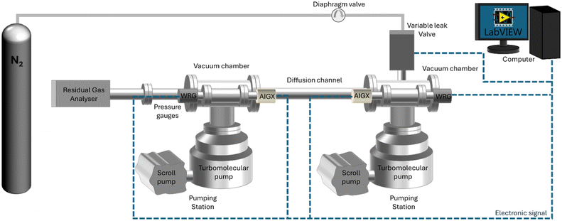
The ultra-high vacuum diffusion setup (UHVDS) was specifically designed and built to study diffusion in a single pore channel aiming to isolate and investigate the sole impact of its geometrical properties. It is schematically represented in Fig. 1. Two gas reservoirs, which are the vacuum chambers in Fig. 1, are placed at both sides of the diffusion channel, which corresponds to the pore channel modelled in fundamental analytical and computational studies. The size of the reservoirs is large enough compared to the pore channel volume. The length-to-diameter ratio varies from 10 to 20, and the Knudsen numbers studied are high (from 1 up to 100).17 The dimensions of the reservoirs allow the gas velocities to follow a Maxwell distribution inside them.15The UHVDS is able to achieve ultra-high vacuum conditions, reaching pressures as low as 10−8 mbar, to ensure smooth injection of a precise amount of gas into the system, and accurate measurements of the parameters required for deriving the Knudsen diffusivity.
The set-up consists of two pump stations (Edwards nEXT Turbo Pumping Station) interconnected with vacuum chambers, with the diffusion channel positioned in between, as depicted in Fig. 1. Each chamber is connected to its dedicated pump set, enabling easier control of the pressure within each chamber and ensuring accurate measurements. Each pump station includes a turbomolecular pump (Edwards nEXT300) with a pumping speed of 300 L s−1 to achieve ultra-high vacuum through combination with a supportive, fore-vacuum pump (Edwards nXDS6i dry scroll pump) to extract the evacuated gas into the atmosphere. The vacuum chambers are three-way cross chambers (custom-made with two additional ports) with an internal volume of approximately 3 L. Each vacuum chamber is equipped with two pressure gauges, a combined Pirani and Penning gauge with a wide range of measuring pressures (10−9–103 mbar, which is the entire operating range of the setup; Edwards Wide Range Gauge, WRG-S-NW25), but with an accuracy of only ±30% at high vacuum conditions, and a hot cathode type gauge with a higher accuracy of ±15% at the targeted ultra-high vacuum pressure range (10−9–10−6 mbar; Edwards Active Ion Gauge, AIGX-S-DN40CF). The operation of the pumps and the pressure gauges can be monitored and controlled through the instrument controller of the pump stations (Edwards Turbo and Instrument Controller, TIC). A residual gas analyzer (SRS RGA 100) is installed at one side of the UHVDS via a DN40CF connection flange for leak detection and mass spectral analysis. The RGA is a quadrupole mass spectrometer that identifies the gas species present in the system and their partial pressure. The intermediate channel that connects the two vacuum chambers is where diffusion is studied. The diffusion channel is a 304 stainless steel tube with an internal diameter of 35 mm that is connected via DN100CF flanges with the two vacuum chambers located at both sides.
All components of the setup, including the gas inlet lines, are constructed from metal, primarily stainless steel, to ensure compatibility with vacuum conditions. Copper and aluminium gaskets are positioned between the CF ConFlat and KF wingnut clamp flanges respectively that were purchased from Kurt J. Lesker to establish leak-tight connections.
Nitrogen gas of N5 grade (BOC, 99.999% purity) is selected as the guest molecule for diffusion studies. The gas is injected into the system using a variable leak valve (VAT Variable Leak Valve Series 590) with a very low leaking rate. The variable leak valve is a gate valve with varying gate positions that can regulate the pressure gradient imposed to the system. A diaphragm valve (Gas-Arc Tech Master GPP400) is installed before the leak valve, which reduces the pressure from 10 bar (at the gas cylinder head) to 0.2 bar, to control the flow of the gas entering the vacuum system. Isolation valves are also installed in the gas lines as an additional safety measure. The pressure gauges and the leak variable valve are connected electrically to a computer for pressure monitoring, with LabVIEW (2020) software chosen to automate the data acquisition process. Heating tapes with a PID temperature controller purchased from RS PRO are installed around the outer surface of the diffusion channel and the vacuum chambers for outgassing purposes, as will be discussed in the next section.
Experimental procedure
Prior to any experiments, the UHVDS is pumped down from atmospheric condition to ultra-high vacuum level (around 10−8 mbar). Leak tests are carried out with helium gas utilizing the RGA; these can aid in the detection of potential leaks that may occur during the assembly, thereby ensuring that the overall leak rate remains minimal. Additionally, conducting a mass spectra analysis with the RGA facilitates the detection of chemical contamination in the system caused by organic molecules, which could degrade pump performance over time.The pumpdown time, which is the time necessary to achieve the target pressure of 10−8 mbar, could typically last a few hours to a month at room temperature depending on the system volume, pumping speed and other parameters, but it can be reduced drastically by thermal outgassing at 120 °C using heating tapes. It is worth mentioning that the pressure of the two vacuum chambers should be close to 10−8 mbar before the start of the experiments and that, during the experiments, the pressure range should be such that the diffusion of the guest gas molecules remains within the Knudsen regime.
The study of Knudsen transport diffusion is performed by introducing a constant gas flow from one side of the system, that creates a pressure gradient between the two sides of the diffusion channel. The transport diffusivity for each experiment can be derived from eqn (6) using this pressure difference that is measured for a specific molar flux. The molar flux can be calculated using eqn (7)–(9) and a simple conversion from pressure to concentration using the ideal gas law. Attention should be given to the value of pressure, as the initial pressure before applying the molar flux should be deduced from the final value of pressure that is measured at the gas inlet. An example of the derivation of the Knudsen transport diffusivity from an experiment can be found in the Appendix.
Pressure measurements are continuously recorded during the experiments using LabVIEW, capturing the asymptotic decrease in pressure until equilibration is achieved, as illustrated in Fig. 2. LabVIEW has been a very helpful tool for the automation of experimentation and pressure monitoring of the UHVDS, as it records 4 experimental points per minute, allowing the user to capture small deviations in pressure.
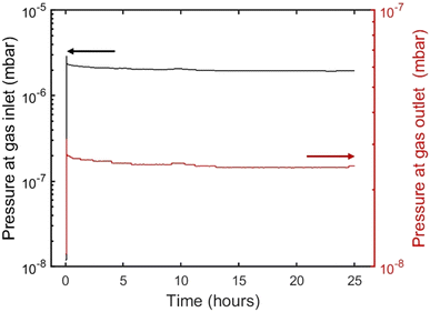 | ||
| Fig. 2 Pressures at the gas inlet and outlet of the pore channel, as measured by the hot cathode (AIGX) pressure gauge (note the different log scales for the inlet and outlet). | ||
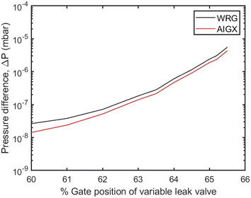
Different molar fluxes of nitrogen gas are imposed via the variable leak valve of the UHVDS, and for each experiment the pressure difference generated at the diffusion channel is measured by the hot-cathode type pressure gauges located at the left and right vacuum chambers, because of their higher accuracy under ultra-high vacuum conditions (Fig. 3). In Fig. 3, the overestimation of the pressure measured by the Penning type (WRG) gauge in comparison to the pressure measured by the hot-cathode type (AIGX) gauge could be explained by the different accuracies of the two types of gauges and the calibration of the WRG gauge. Carrying out experiments at different gas flow rates is important to test that the derived transport diffusivity is independent of the concentration, as should be in the Knudsen regime. To ensure this, it should be highlighted that the measurements should be stopped only after the system reaches the equilibrium pressure. Therefore, the pressure used for the derivation of the diffusivity should be adjusted to the final, asymptotic value. In addition, multiple (2–4) measurements were conducted for each imposed molar flux to ensure better accuracy of the experimental results. By obtaining the asymptotic pressure value, the experimental, statistical error between different repetitions of measurements is minimized.
Experimental realization of channel geometries
The UHVDS can be used to measure accurately the Knudsen diffusivity in channels with different geometries. The experimental results from the model geometries can be extrapolated to diffusion in nanoporous materials, so that the sole effect of a specific geometric characteristic – such as pore length, pore shape, and pore diameter – on Knudsen diffusion can be understood without the inherent flaws of experimental studies in nanoporous materials, as discussed in Introduction.Pore length
To investigate the effect of pore length, two stainless steel channels were manufactured with varying length of 250 mm and 500 mm (Fig. 4). Both pore channels have a circular cross section with a 22.1 mm internal diameter, leading to a length-to-diameter ratio of approximately 10 and 20, respectively. The selection of the diameter is important, as it affects the level of vacuum that is necessary inside the UHVDS to study diffusion at high Knudsen numbers. The pore channels were custom-made by Kurt J. Lesker with DN100CF flanges (one rotatable and one fixed) welded at both ends to provide leak-tight connections. It can be noted that the vacuum welds passed the leak detection check with a mass spectrometer using helium gas prior to any assembly to ensure that no leaks were present in the welded areas.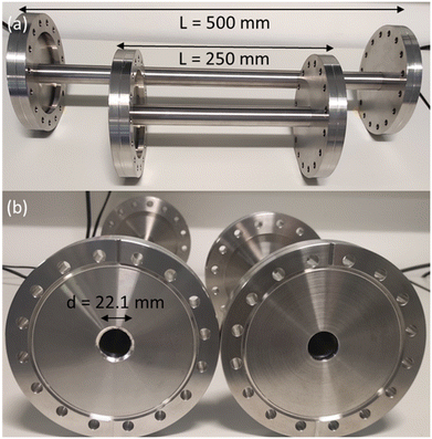 | ||
| Fig. 4 Photograph of stainless-steel channels with: (a) varying length of 250 mm and 500 mm, and (b) circular cross section with the same diameter of 22.1 mm. | ||
The experimental procedure described in the respective section was followed to study Knudsen transport diffusion. Each channel shown in Fig. 4 was assembled within the UHVDS and, after the pumpdown procedure, leak testing and degassing, a constant molar flux was applied to one side and the pressure was recorded. A series of measurements was conducted for each channel by varying the molar flux. The Knudsen transport diffusivity was derived every time as illustrated in Fig. 5. The transmission probability was calculated using eqn (8) and is equal to 0.1 for the pore channel of 250 mm length, and 0.056 for the pore channel of 500 mm length (Table 1).
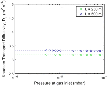 | ||
| Fig. 5 Knudsen transport diffusivity for the channels with 250 mm (green) and 500 mm (blue) length for varying pressure gradient at the gas inlet using the UHVDS. | ||
| Pore channel characteristics | Transmission probability, ft | Average experimental Knudsen transport diffusivity, DK,t,exp | Theoretical Knudsen diffusivity, DK,th |
|---|---|---|---|
| SS, circular cross section, d = 22.1 mm, L = 250 mm | 0.105 | 3.18 | 3.11 |
| SS, circular cross section, d = 22.1 mm, L = 500 mm | 0.056 | 3.33 | 3.29 |
| SS, square cross section, d = 19.6 mm, L = 500 mm | 0.050 | 2.98 | 2.93 |
| HTR, square cross section, d = 17 mm, L = 500 mm | 0.043 | 2.57 | 2.56 |
It can be deduced from Fig. 5 that the length of the channel has only a minor effect on the Knudsen diffusivity. The average experimental and theoretical values of the Knudsen transport diffusivity for the short and long channels are presented in Table 1. The theoretical value of the Knudsen diffusivity is obtained by combining eqn (1) with eqn (8) to correct for the finite length of the channel, leading to:
 | (10) |
Pore shape
To study the effect of the pore shape, two stainless steel channels were manufactured with a square and a circular cross section (Fig. 6). The pore channel with the square cross section has a 19.6 mm hydraulic diameter according to eqn (9), while the one with the circular cross section has a 22.1 mm diameter. Both pore channels have the same cross-sectional area and the same length of 500 mm, corresponding to L/d ∼ 20. The two stainless steel pore channels were also custom-made the welded areas passed a leak detection check with a mass spectrometer using helium gas.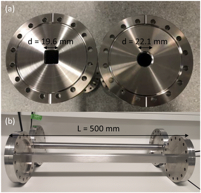 | ||
| Fig. 6 Photographs of two stainless-steel channels of: (a) varying pore shape with a square and a circular cross section of the same area, and (b) same pore length of L = 500 mm. | ||
Again, a series of measurements was conducted for each pore channel according to the experimental procedure for the study of Knudsen transport diffusivity by applying a constant and varying molar flux on one side of the diffusion channel and recording the pressure. The Knudsen diffusivity was derived for every inlet pressure and results are shown in Fig. 7; the average experimental value for each channel is presented in Table 1. Here, the two pore geometries have a transmission probability of ∼0.05–0.06 (Table 1), as the pore channels have approximately the same hydraulic diameter and length. In Fig. 7, the derived Knudsen diffusivity of the pore channels with circular and square cross section have a ∼10% difference that could be attributed to the effect of pore size, as there is a small deviation in the hydraulic diameter. However, the experimental values are very close to the theoretical values shown in Table 1 with a 1.3% and 1.6% difference between experiments and theory for the channel of circular and square cross section, respectively.
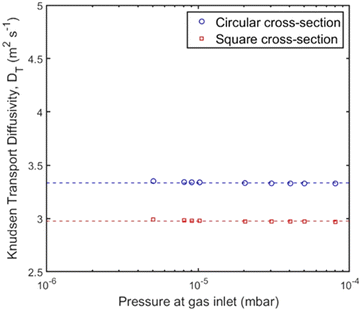 | ||
| Fig. 7 Knudsen transport diffusivity for the channels with circular (blue circles) and square (red squares) cross section for varying pressure gradient at the gas inlet using the UHVDS. | ||
3D-printed pore channel
The capability of the UHVDS to study the effect of pore channel geometries can be expanded by extending the type of materials and manufacturability of more complex geometries. Two important parameters to consider during the design of the system are the compatibility of the components' material and the manufacturing techniques. The choice of the right material plays a crucial role in controlling the base pressure, i.e., the lowest value of the pressure that the ultra-high vacuum system can reach. At the same time, it is essential to evaluate the available manufacturing processes for producing these components. When the geometry of the pore channel becomes complex and common manufacturing techniques, such as extrusion, moulding or machining, are impractical, 3D printing technologies emerge as a viable alternative.Several metals, especially stainless steels, are good candidates and are very widely used in ultra-high vacuum systems due to their favourable properties, such as their robustness, inertness, lack of porosity, and familiar ways to machine. However, the use of metal is impeded by the high cost of metal 3D-printing,48 especially for larger pieces, and, thus, polymers were considered as potential materials for the fabrication of diffusion channels. The choice of the right polymeric material and manufacturing technology are important to overcome the inherent flaws originating from the material itself and from the additive manufacturing process.49 For this reason, the use of plastics in vacuum applications has, until recently, been prohibitive for large parts.50 With the rising potential of additive manufacturing techniques, the commercialization of equipment, and the development of new, more robust materials with improved physical or chemical properties, the use of plastics in vacuum applications is actively being re-examined for various purposes.51–54
In this study, the materials chosen for 3D printing were PA2200 nylon and high-temperature resin. PA2200 nylon was used in a selective laser sintering (SLS) (EOS Formiga P100) 3D printer, while high-temperature resin (RS-F2-HTAM-02, Formlabs) was used in a stereolithography (SLA) (Formlabs Form 3) 3D printer. Both SLS and SLA 3D printing are light-based technologies that are commercially available and can offer adequate printing quality and good printing times.55,56 For the SLS 3D printing, the 3D printing build rate was 20 mm height per hour, while for SLA 3D printing, the smallest layer thickness of 25 μm was used, and the smallest size supports of 0.3 mm to achieve a great printing quality. PA2200 nylon is a polyamide 12 powder with titanium dioxide additives that can produce high-strength parts with a smooth surface. High-temperature resin (HTR) is a photopolymerization resin that has high thermal stability,57 making it an ideal candidate for application in an ultra-high vacuum environment, as outgassing at higher temperatures can help achieve lower values of the ultimate pressure.
To improve the vacuum properties of the material, a post-process procedure was followed, which includes the following steps. First, chemical cleaning with ethanol or isopropanol, depending on the material used in each 3D printing technique, to remove excess nylon powder or uncured resin and/or any other possible chemicals, dust, or oils that can cause chemical contamination. Second, for the part made by an SLA 3D printer, post-curing in a UV curing station provided by Formlabs at 80 °C for 2 h to improve the mechanical strength and stability of the parts by full solidification.57 Third, a heating treatment, called outgassing, at 65 °C for 24 h for the SLS 3D-printed part and at 180 °C for 8 hours for the SLA 3D-printed part under rough vacuum, followed by 24 hours at room temperature in a vacuum oven (Jeio Tech OV-12) to lower the outgassing rate.53 Finally, the parts were stored inside a desiccator with careful handling to avoid contamination.
After the post-treatment, the 3D-printed piece was fitted into the stainless-steel diffusion channel of the UHVDS and, after assembly, the UHVDS was left to pump down until it reached the base pressure. Only a small part made by the SLS 3D printer was used, while the total channel was used for the part made by the SLA 3D printer. However, due to the desired total length of the channel (500 mm) and the limitations in the maximum print size of the 3D printer (50 mm), the total channel could not be fabricated as one piece. For this reason, the channel was divided into smaller segments and appropriate connections were added in the design of each segment. To ensure secure bonding and airtight connections, it is recommended to use an epoxy adhesive (such as Araldite 2020), well-suited for ultra-high vacuum applications, to bond successive pieces before inserting the complete channel into the vacuum setup.
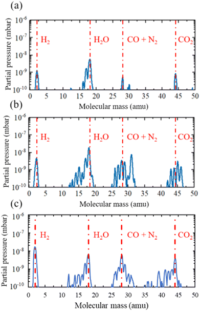
When the base pressure of around 10−8 mbar was reached, the vacuum compatibility of the 3D printed materials was tested by performing a residual gas analysis (RGA), as suggested by Povilus et al.,51 using the RGA quadrupole mass spectrometer of the UHVDS. The outgassing properties were assessed in three settings: the UHVDS with the empty stainless-steel diffusion channel, the UHVDS with the 3D printed piece made by SLS inside the diffusion channel, and the UHVDS with the 3D printed pore channel made by SLA respectively. The resulting graphs are presented in Fig. 8.
Each graph contains valuable information about the gas species that are present inside the UHVDS and their amount, as partial pressure. It is clear from Fig. 8 that Nylon 12 is unsuitable for vacuum application, as its outgassing property of one small piece is high and is expected to increase for the total channel. On the other hand, the HTR is deemed suitable for ultra-high vacuum applications, as the outgassing properties of the total channel are similar to the outgassing properties of a single piece made by SLS. This result agrees with the finding of Kellermeier et al.,53 where they tested the outgassing of various samples of high-temperature resin subjected to different post-treatment conditions, using an RGA and showed that the HTR is compatible with ultra-high vacuum applications. It is obvious from Fig. 8 that the need for outgassing is increased significantly when using 3D printed polymers and their use should be considered only in cases where metals cannot be used.
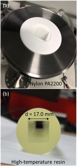
Two channels with square cross section were designed as test geometries with a 3D CAD software and were manufactured using the SLS and SLA 3D printing from PA2200 nylon and HTR, respectively (Fig. 9). The 3D printed channels have an inner diameter of 17 mm, outer diameter of around 35 mm, and a length of 500 mm. These channels were pre-treated and inserted into a stainless-steel tube with a circular cross section that has an inner diameter of 35 mm, and a length of 500 mm, and which can be connected to the vacuum chambers on both ends via DN100CF flanges, as pictured in Fig. 9a. Both pore channels were leak tested on-site with helium using the RGA after the assembly and pumpdown of the UHVDS, and thermal outgassing was performed according to the experimental procedure. Due to the excessive outgassing of the PA2200 nylon material, the base pressure of the UHVDS was too high and no experiments could be performed. In contrast, the HTR has proven to be compatible with ultra-high vacuum applications and the base pressure of the UHVDS with the total pore channel of 500 mm length inserted into the diffusion channel reached the target pressure of around 10−8 mbar.
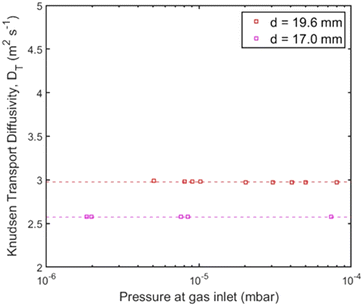
When the UHVDS achieved the base pressure, experimental measurements were conducted with a constant molar flux applied to one side of the vacuum chamber. The Knudsen diffusivity was derived using the pressure recordings over time and acquiring the pressure after equilibration. A series of experiments was performed under different molar fluxes. The pore channel of high-temperature resin was compared to the stainless-steel channel with a square cross section pictured on the left in Fig. 6a that has a diameter of 19.6 mm and a length of 500 mm. The transmission probability of the stainless-steel channel is 0.050, and of the high-temperature resin channel is 0.043 (Table 1). The experimental results from the transport diffusion studies are shown in Fig. 10.
Based on the results in Fig. 10, it can be observed that the experimental diffusivity for the channel with the smaller diameter made by high temperature resin is smaller than the diffusivity for the stainless-steel pore channel, in a ratio that agrees quite well with the theoretical values. The average experimental Knudsen transport diffusivity and theoretical Knudsen diffusivity for the pore channel made with 3D printing are displayed in Table 1. This evidence also supports that the 3D printing technique can be further utilised to construct more complex pore geometries for future studies of Knudsen diffusion using the UHVDS.
Summary
An experimental technique to derive the transport diffusivities and help pinpoint the sole effect of pore length and pore shape on Knudsen diffusion is presented. Instead of a direct experimental investigation using nanoporous materials, a scale up of a single pore channel from the nanometre to the centimetre scale is preferred to isolate a single geometrical characteristic. A unique-purpose setup, called Ultra-High Vacuum Diffusion Setup (UHVDS), has been designed and built with a vacuum chamber and a turbomolecular pump station at each side of the diffusion channel. The ultra-high vacuum conditions generated by the pump station help to achieve the same Knudsen numbers that prevail in the mesopores in the magnified pore channel.The experimental procedure for the studies of transport diffusion mainly includes the application of a constant flow of nitrogen gas with precise control from one side of the channel over a time of 24 h until pressure equilibration is achieved. The pressure difference between the two ends of the channel after equilibration is used to derive the Knudsen transport diffusivity. Different molar fluxes were tested to ensure that there is no dependence of the diffusivity on the number of gas molecules.
Three case studies were conducted, in which different channels were experimentally prototyped to test the effects of pore length, pore shape, and pore diameter, respectively. For the effect of the pore length, two channels of the same diameter and cross-sectional shape were manufactured with lengths of 250 mm and 500 mm. The experimental results from the studies of Knudsen transport diffusion showed that the diffusivity is only slightly affected by the pore length. The Knudsen diffusivity for the 500 mm channel was observed to be greater than the diffusivity of the 250 mm channel by a small percentage that agreed very well with Dushman's equation. For the effect of the pore shape, two channels with circular and square cross section of the same hydraulic diameter and the same length were manufactured and tested with the UHVDS. The Knudsen transport diffusivity of the channel with the square cross section is close to the diffusivity of the circular channel with, however, a small deviation that could be due to a small difference in hydraulic diameter between the two channels, but also to unequal accessibility along the rim of the square channel compared to a circular channel, as predicted by Smoluchowski. For the effect of pore diameter, two channels with a square cross section and a diameter of 17 mm were designed and manufactured via 3D printing. A residual gas analysis was performed using a quadrupole mass spectrometer to determine the vacuum compatibility of Nylon PA2200 and high-temperature resin used in SLS and SLA 3D printing, respectively, with the UHVDS. The results revealed that, among these materials, only high-temperature resin is deemed appropriate for the UHVDS, as the outgassing properties of Nylon PA2200 led to an elevated base pressure within the UHVDS, which is unsuitable for experiments at high Knudsen numbers. Possible solutions to improve the compatibility of the material are to increase the outgassing time during the post-processing procedure from a few hours to a week and to apply a vacuum-compatible coating or sealant, such as VacSeal54 or Stycast.58 The channel made from high-temperature resin was tested experimentally in the UHVDS, and the results were compared with the stainless-steel channel used in the second case study. The average experimental Knudsen transport diffusivity for the channel made from high-temperature resin is smaller than the one for the stainless-steel channel, as the diameter of the first is smaller than the diameter of the latter. The diffusivity changes proportionally to the diameter in agreement with theoretical predictions.
This work opens new pathways to investigate experimentally the effects of geometrical characteristics of the pores of nanoporous materials on Knudsen diffusion by using magnified representations of those pores and comparing the results with other analytical, computational, or experimental results. For example, more channels with converging–diverging and sinusoidal geometry could be realised to investigate the effect of channel tortuosity. Nevertheless, it is important to note that when utilizing magnified representations of pore channels, potentially influential phenomena associated with nanopores, such as physico-chemical nano-confinement effects or surface diffusion, may not occur. For the same reason, when operating under ultra-high vacuum conditions, effects like capillary condensation and pore filling, which typically occur at higher pressures in porous materials, cannot be considered. In addition, the type of material used here is usually not the same as in actual nanoporous materials. Therefore, the surface interaction between the gas molecules and the pore walls are expected to be different. This is, however, also an advantage, as it allows us to isolate the impact of geometrical effects. The main aim of this article was to present the design and implementation of an ultra-high vacuum diffusion setup with a detailed description of the experimental procedure to study Knudsen diffusion, to validate its operation, and to discuss the challenges but also the tremendous opportunities for fundamental studies of this important type of transport phenomenon.
Data availability
Please see the accompanying statement.Author contributions
Maria Mourkou: writing – original draft, review & editing, conceptualization, methodology, investigation, data curation, formal analysis, visualization. Haiyue Yu: conceptualization, methodology, investigation, data curation. Sander Baltussen: conceptualization, methodology. Nicholas Snead: investigation – support, resources – provision of heating control unit, software – LabVIEW development. Nidhi Kapil: writing – review & editing. Marc-Olivier Coppens: writing – review & editing, conceptualization, supervision, project administration, funding acquisition.Conflicts of interest
There are no conflicts to declare.Appendix
An example calculation for the derivation of the experimental Knudsen transport diffusivity will be presented here for clarification. Let's assume as a demonstration case a channel with a square cross section that has 17 mm edge length and 500 mm channel length.According to eqn (9), the hydraulic diameter for the pore channel is:
The base pressure of the UHVDS is measured using the AIGX gauge before the start of the experiment and it is P1,0 = 1.43 × 10⁻⁸ ± 2.15 × 10⁻⁹ mbar in the right vacuum chamber, and P2,0 = 1.38 × 10⁻⁸ ± 2.07 × 10⁻⁹ mbar in the left vacuum chamber.
The variable leak valve that is connected to the right vacuum chamber is opened at 64%, and the pressure of the UHVDS is recorded over time and decreases asymptotically until equilibrium is reached. The equilibration pressure is P1,eq = 2.68 × 10⁻⁷ ± 4.02 × 10⁻⁸ mbar in the right vacuum chamber and P2,eq = 1.55 × 10⁻⁸ ± 2.33 × 10⁻⁹ mbar in the left vacuum chamber.
To calculate the molar flux that is imposed at the right vacuum chamber, eqn (7) is used.
From the ideal gas law: PV = nRT → P = CRT → C = P/RT, and from the kinetic theory of gases:  for nitrogen gas at a constant temperature of 295.15 K during the experiments. Replacing the two equations in the equation for the molar flux, leads to:
| J = 5.30 × 10⁻¹⁰(±7.95 × 10⁻¹¹) mol m−2 s−1 |
| DKt,exp = 2.57 m2 s−1 |
Acknowledgements
The authors gratefully acknowledge Professor Asterios Gavriilidis for providing access to 3D printing facilities, and Synfuels China for funding this research project, with additional support from the EPSRC (“Frontier Engineering: Progression” award, EP/S03305X/1).Notes and references
- R. R. Melkote and K. F. Jensen, AIChE J., 1989, 35(12), 1942–1952 CrossRef CAS.
- J. Kärger, D. M. Ruthven and R. Valiullin, Chem. Int., 2021, 43(3), 25–29 Search PubMed.
- R. Gläser, J. Kärger and D. M. Ruthven, Chem. Ing. Tech., 2021, 93(6), 893–901 CrossRef.
- J. C. Palmer, J. D. Moore, J. K. Brennan and K. E. Gubbins, Adsorption, 2011, 17(1), 189–199 CrossRef CAS.
- J. Caro, Adsorption, 2021, 27(3), 283–293 CrossRef CAS.
- J. J. E. Maris, D. Fu, F. Meirer and B. M. Weckhuysen, Adsorption, 2021, 27(3), 423–452 CrossRef CAS.
- S. Xu, K. Zheng, C. R. Boruntea, D. Cheng, F. Chen, G. Ye, X. Zhou and M.-O. Coppens, Chem. Soc. Rev., 2023, 52(12), 3991–4005 RSC.
- C. H. Sharp, B. C. Bukowski, H. Li, E. M. Johnson, S. Ilic, A. J. Morris, D. Gersappe, R. Q. Snurr and J. R. Morris, Chem. Soc. Rev., 2021, 50(20), 11530–11558 RSC.
- Q. Zheng, J. Williams, L. R. van Thiel, S. V. Elgersma, M. D. Mantle, A. J. Sederman, T. A. Baart, G. Leendert Bezemer, C. M. Guédon and L. F. Gladden, Nat. Catal., 2023, 6(2), 185–195 CrossRef CAS.
- B. C. Bukowski, F. J. Keil, P. I. Ravikovitch, G. Sastre, R. Q. Snurr and M.-O. Coppens, Adsorption, 2021, 27(5), 683–760 CrossRef CAS.
- R. Valiullin, Chem. Int., 2015, 38(1), 24 Search PubMed.
- M.-O. Coppens and A. J. Dammers, Fluid Phase Equilib., 2006, 241(1–2), 308–316 CrossRef CAS.
- F. J. Keil, Comput. Math. Appl., 2013, 65(10), 1674–1697 CrossRef.
- F. J. Keil, Annu. Rev. Chem. Biomol. Eng., 2018, 9, 201–227 CrossRef.
- D. H. Davis, J. Appl. Phys., 1960, 31(7), 1169–1176 CrossRef.
- S. Varoutis, D. Valougeorgis and F. Sharipov, Rarefied gas flow through tubes of finite length, in Rarefied Gas Dynamics: 26th International Symposium, 2009 Search PubMed.
- V. A. Titarev, Vacuum, 2013, 94, 92–103 CrossRef CAS.
- J. W. Evans, M. H. Abbasi and A. Sarin, J. Chem. Phys., 1979, 72(5), 2967–2973 CrossRef.
- M. H. Abbasi, J. W. Evans and I. S. Abramson, AIChE J., 1983, 29(4), 617–624 CrossRef CAS.
- Y. Nakano, S. Iwamoto, I. Yoshinaga and J. W. Evans, Chem. Eng. Sci., 1987, 42(7), 1577–1583 CrossRef CAS.
- V. N. Burganos and A. C. Payatakes, Chem. Eng. Sci., 1992, 47(6), 1383–1400 CrossRef CAS.
- D. H. Davis, L. L. Levenson and N. Milleron, J. Appl. Phys., 1964, 35(3), 529–532 CrossRef.
- B. T. Porodnov, P. E. Suetin, S. F. Borisov and V. D. Akinshin, J. Fluid Mech., 1974, 64(3), 417–438 CrossRef.
- Y. Ji, K. Yuan and J. N. Chung, Int. J. Heat Mass Transfer, 2006, 49(7–8), 1329–1339 CrossRef CAS.
- Z. Chai, Z. Guo, L. Zheng and B. Shi, J. Appl. Phys., 2008, 104(1), 014902 CrossRef.
- O. Sazhin, Microfluid. Nanofluid., 2020, 24(4), 27–35 CrossRef CAS.
- L. Marino, Microfluid. Nanofluid., 2009, 6(1), 109–119 CrossRef CAS.
- S. Gruener and P. Huber, Phys. Rev. Lett., 2008, 100(6), 1–5 CrossRef.
- M. Knudsen, Ann. Phys., 1909, 333(1), 75–130 CrossRef.
- M. Knudsen and W. J. Fisher, Phys. Rev., 1910, 31(5), 586–588 Search PubMed.
- W. Steckelmacher, Rep. Prog. Phys., 1986, 49(10), 1083–1107 CrossRef CAS.
- R. Li and Y. Yang, Phys. Fluids, 2023, 35(3), 032010 CrossRef CAS.
- P. Clausing, Ann. Phys., 1930, 396(5), 533–566 CrossRef.
- M. Smoluchowski, Ann. Phys., 1910, 338(16), 1559–1570 CrossRef.
- J. C. Maxwell, Philos. Trans. R. Soc. London, 1879, 170, 231–256 CrossRef.
- W. Gaede, Ann. Phys., 1913, 346(7), 289–336 CrossRef.
- F. Celestini and F. Mortessagne, Phys. Rev. E, 2008, 77(2), 021202 CrossRef.
- A. Argönül and F. J. Keil, Period. Polytech., Chem. Eng., 2008, 52(2), 37–55 CrossRef.
- C. Cercignani and M. Lampis, AIAA J., 1997, 35(6), 1000–1011 CrossRef CAS.
- S. K. Bhatia and D. Nicholson, Chem. Eng. Sci., 2011, 66(3), 284–293 CrossRef CAS.
- S. K. Bhatia, M. R. Bonilla and D. Nicholson, Phys. Chem. Chem. Phys., 2011, 13(34), 15350–15383 RSC.
- D. M. Ruthven, W. J. DeSisto and S. Higgins, Chem. Eng. Sci., 2009, 64(13), 3201–3203 CrossRef CAS.
- R. Metzler, J. H. Jeon, A. G. Cherstvy and E. Barkai, Phys. Chem. Chem. Phys., 2014, 16(44), 24128–24164 RSC.
- P. Clausing, J. Vac. Sci. Technol., 1971, 8(5), 636–646 CrossRef.
- S. Dushman, The production and measurement of high vacuum, General Electric Co., New York, 1922 Search PubMed.
- Y. Shi, Y. T. Lee and A. S. Kim, Transp. Porous Media, 2012, 93(3), 517–541 CrossRef CAS.
- S. E. Albo, L. J. Broadbelt and R. Q. Snurr, Chem. Eng. Sci., 2007, 62(23), 6843–6850 CrossRef CAS.
- M. Bergin, T. A. Myles, A. Radić, C. J. Hatchwell, S. M. Lambrick, D. J. Ward, S. D. Eder, A. Fahy, M. Barr and P. C. Dastoor, J. Phys. D: Appl. Phys., 2022, 55(9), 1–5 CrossRef.
- K. Jousten, Handbook of Vacuum Technology [Internet], Wiley-VCH, Weinheim, Germany, 2016 Search PubMed.
- Center for the Advancement of Natural Discoveries using Light Emission, Vacuum Technology Practice Course (Support Material) [Internet], 2019.
- A. P. Povilus, C. J. Wurden, Z. Vendeiro, M. Baquero-Ruiz and J. Fajans, J. Vac. Sci. Technol., A, 2014, 32(3), 033001 CrossRef.
- T. Chaneliere, Vacuum compatibility of ABS plastics 3D-printed objects, 2017 Search PubMed.
- M. Kellermeier, S. Zinsli, U. Dorda, R. Ischebeck, J. Lehmann and B. Hermann, et al. , J. Phys.: Conf. Ser., 2020, 1596(1), 1–11 Search PubMed.
- J. Li, T. Mcpartland, B. Gutierrez, J. Pedersen and Y. Zhou, Vacuum, 2024, 220, 112769 CrossRef CAS.
- R. L. Truby and J. A. Lewis, Nature, 2016, 540(7633), 371–378 CrossRef CAS.
- J. C. Ruiz-Morales, A. Tarancón, J. Canales-Vázquez, J. Méndez-Ramos, L. Hernández-Afonso, P. Acosta-Mora, J. R. Marín Rueda and R. Fernández-González, Energy Environ. Sci., 2017, 10(4), 846–859 RSC.
- Formlabs, High Temp Resin [Internet], 2022 Search PubMed.
- R. Poggiani, Tech. Note, 2009, ET-026-09(1) Search PubMed.
| This journal is © The Royal Society of Chemistry 2024 |

