Crystalline porous materials in perovskite solar cells: a mutually beneficial marriage
Chi
Li
 abc and
Peng
Gao
 *abc
*abc
aState Key Laboratory of Structural Chemistry, Fujian Institute of Research on the Structure of Matter, Chinese Academy of Sciences, Fuzhou 350002, China. E-mail: peng.gao@fjirsm.ac.cn
bLaboratory for Advanced Functional Materials, Xiamen Institute of Rare Earth Materials, Haixi Institute, Chinese Academy of Sciences, Xiamen 361021, China
cUniversity of Chinese Academy of Sciences, Beijing 100049, China
First published on 9th February 2024
Abstract
The remarkable efficiency achieved by metal halide perovskite solar cells (PSCs) has established them as a significant advancement in thin-film photovoltaic technology in recent years. However, the susceptibility of halide perovskite to degradation under aging stressors presents a substantial impediment to their commercial viability. Leveraging attributes such as structural design flexibility, precise functional control, an abundance of functional sites, and a combination of rigidity and flexibility, crystalline porous materials (CPMs) have emerged as promising additives and interfacial modifiers. CPMs play a pivotal role in influencing perovskite crystallization, defect passivation, filtering of ultraviolet photons, and the adsorption of leaked Pb(II) ions, garnering increasing attention within the PSC research community. In this review, we systematically categorize and assess the multifaceted functions of CPMs within various functional layers of PSCs, encompassing the charge transport layer, perovskite heterojunction, and the perovskite/charge transport interfacial layer. Additionally, we conducted an extensive literature data analysis to categorize the specific roles of CPMs across these functional layers and investigated their correlation with device photovoltaic parameters. Finally, we present conclusions and offer insights into the future prospects of CPM-based PSCs. This timely review provides a distinctive perspective on the field and promises to yield valuable insights for the ongoing development of these promising materials.
1. Introduction
Organic-inorganic halide perovskite solar cells (PSCs) have developed rapidly due to their superior optoelectronic properties such as high absorption coefficients, excellent charge carrier mobility, long charge carrier lifetime, and defect tolerance, the power conversion efficiency (PCE) of PSCs swiftly increased from 3.8% to 26.1% over the past decade.1–5 In addition, owing to the abundant raw material, the relatively low preparation cost, and the more straightforward fabrication process, PSCs, as a game-changer, have been prompted to be an up-and-coming candidate in replacing the dominating silicon solar cells.6,7 Currently, due to some external factors (e.g., moisture,8 thermal,9 metal ions from electrode,10 and UV light irradiation11) and internal factors (e.g., diverse crystal structure,12 ion migration,13 and residual strain14), the presence of ubiquitous defects typically leads to diminished stability of perovskite by accelerating the decomposition of perovskite. Another challenge limiting the commercialization of PSCs is the potential toxicity of Pb and its detrimental environmental impacts.15–17 To address issues of stability and Pb toxicity, various approaches such as encapsulation,18 solvent engineering,19 structural engineering,20 ion adsorption,21 and surface barrier22 are widely used. Although materials with either effect have been reported, one that simultaneously meets the above two requirements has barely been demonstrated due to the functional limitations of the small molecular materials.Crystalline porous materials (CPMs) are a type of porous materials with long-range ordered periodic network skeletons formed by self-assembly between metal ions and organic ligands or organic molecules through coordination or weak interactions and covalent interactions.23 As one of the rapidly developing systems in the current field of materials, CPMs have attracted the attention of researchers because of their interpretable internal structure, an advantage that other amorphous materials cannot match. CPMs usually include metal–organic frameworks (MOFs), covalent-organic frameworks (COFs), and hydrogen-bonded organic frameworks (HOFs). MOFs are a new class of porous crystalline materials constructed by bridging metal ions or metal clusters and organic ligands through coordination bonds, also known as porous coordination polymers. Compared with traditional porous materials, MOFs are characterized by different combinations of metal ions and organic ligands, which have the features and advantages of structural predictability, high porosity and specific surface area, structural diversity, and an easily functionalized framework. Since the concept of MOFs was proposed for the first time in 1995, MOFs have attracted more and more attention and have gradually become one of the most rapidly developing research directions.24,25 COFs are a class of porous materials with regular lattice structures formed by covalent bonds of lightweight elements (e.g., C, H, O, N, B, etc.). These materials exhibit crystalline structures with well-defined porosity, offering high surface areas and tunable pore sizes. COFs possess unique properties such as high thermal and chemical stability, making them promising candidates for various applications, including gas storage and separation, catalysis, optoelectronics, and sensing. Their modular and designable nature allows for precise control over their structure and properties, enabling tailored applications in diverse fields of research and technology.26,27 HOFs are a new type of crystalline porous materials, which are frameworks assembled by organic units through hydrogen-bonding interactions, including pure organic parts and metal-containing organic parts, and these frameworks can be further strengthened by other weak interactions such as π⋯π interactions, van der Waals interactions, C–H⋯π interactions, etc28,29. The structural schematic illustration and definitional differences between the three are shown in Fig. 1a–c, MOFs are a type of crystalline porous framework material with a periodic network structure formed by self-assembling organic ligands and metal ions through coordination bonds, COFs are crystalline organic porous polymers based on covalent bonding, while HOFs are a new type of crystalline porous framework material formed by non-covalent intermolecular hydrogen bonds. Because CPMs have the advantages of large specific surface area, adjustable pore diameter, and pore modification, they are widely used in gas adsorption, proton conduction, catalysis, sensing, drug delivery, and other fields.30–35 Both MOFs and COFs are highly conjugated scaffolds due to their tunable electronic properties, remarkable photo- and thermal stability, easy and relatively low-cost synthesis, and structural versatility,36 and HOFs have some unique features such as mild synthesis condition, solution processability, easy healing, and regeneration,28 which would allow tuning the electronic properties of these materials and change their charge transfer capabilities by slightly modifying the metal centers (MOFs) and the organic linkers (MOFs, COFs, HOFs), which are characteristics that make them well suited for PV applications and accounts for the tremendous increase in the popularity of CPMs in PSCs.
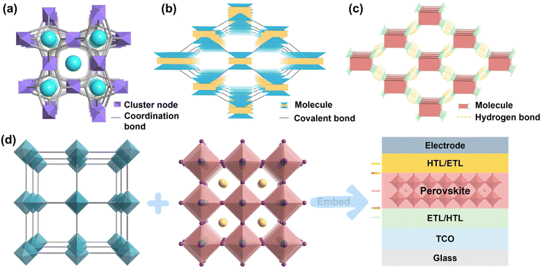 | ||
| Fig. 1 Classification diagram of CPMs. (a) MOFs. (b) COFs. (c) HOFs. (d) Schematics of CPMs model, metal-halide perovskite and its application in various functional layers of PSCs. | ||
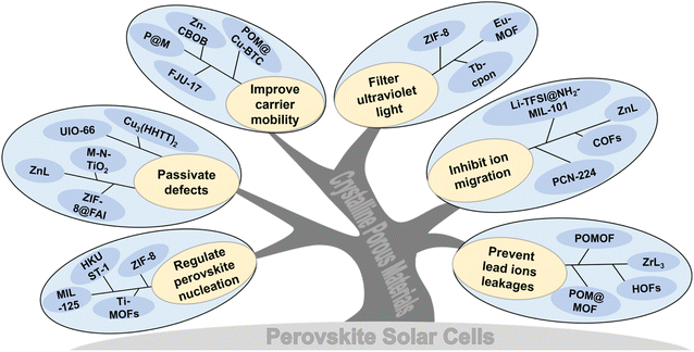
Currently, CPMs (especially for MOFs) are widely used in PSCs. Generally, CPMs play the following roles: regulating perovskite crystallization and improving the quality of perovskite films; passivating defects and inhibiting carrier recombination; improving carrier mobility and promoting transport; UV filtration and adsorption of Pb(II) (Pb2+) ions, etc. Herein, we present an overview of CPMs as/in each functional layer of PSCs and highlight their significance and uniqueness. As shown in Fig. 1d, significant applications in the field can be classified into the following situations: (1) CPMs serving as the charge transport layer (CTL) or blending into the CTL; (2) CPMs mixed with the perovskite to form a hybrid MOF/perovskite heterojunction layer; (3) MOFs serve as the interfacial layer between the CTL and the perovskite interface. Besides the comprehensive review, we also summarized and proposed challenges and opportunities in this research field, which is significant in realizing high efficiency, high stability, and commercialization of PSCs.
2. CPMs-based film fabrication
Due to the typically low solubility of CPMs, especially MOFs, it is challenging to form flat and thin layers in perovskite solar cells, which can compromise the quality of the functional layer. Therefore, different types of CPMs with varying functionalities and solubilities are classified and discussed.2.1. Low solubility CPMs
2.2. Soluble CPMs
Although most MOFs have low solubility, not all MOFs are suitable for photovoltaic applications. In practical applications of PSCs, some MOFs used typically exhibit higher solubility.43,44 Unlike MOFs, which are typically composed of metal ions or clusters coordinated with organic ligands through coordination bonds, resulting in a more stable structure and thus lower solubility, COFs and HOFs are formed by organic molecules connected via covalent bonds or hydrogen bonds, making their structures more flexible and thus typically exhibiting higher solubility. Soluble CPMs are typically introduced through additives or interface layers and can be easily formed into flat and thin layers through spin-coating.2.3. Insoluble dispersions
Mesoporous perovskite solar cells typically employ mesoporous titanium oxide or other mesoporous as the substrate, covered with a perovskite film. When MOFs are utilized as the mesoporous layer or modification layer,45–50 their solubility is typically of lesser concern, as they generally exist in a mesoporous form and serve a supporting role. Similarly, the NiO nanoparticles derived from MOFs and the composite electrodes also do not necessitate considerations regarding solubility issues. Ghorashi et al. synthesized core–shell CuO@NiO nanospheres by calcining Cu–Ni bimetallic MOFs, achieving superior performance compared to NiO-based PSCs.51 Zhang et al. prepared Co-NC (HCl) composite materials with a large specific surface area by etching pyrolyzed ZIF-67 with HCl and combined it with commercial conductive carbon paste in different proportions to prepare carbon-based PSCs.522.4. In situ growth
Compared to spin coating, in situ growth of CPM films enables the fabrication of large-area films with high uniformity and controllable thickness while also minimizing material wastage. Yan et al. first utilized a self-assembly method to fabricate ultra-thin 2D c-MOF Cu3(HHTT)2 films and employed them as HTLs in MA-free mixed Pb–Sn PSCs.53 Zou et al. utilized a lift-off method to transfer the Ni3(HITP)2 film grown at the gas–liquid interface onto ITO, effectively transporting holes from the perovskite film to the anode.543. Progress of CPMs-based PSCs
3.1. CPMs as or in the electron transport layer
The electron transport layer (ETL), as one of the essential components of PSC, can be used to transmit photo-generated electrons and inhibit the recombination of carriers, which is of great significance in improving the photovoltaic performance of the cell. The selection of materials should follow the following principles: (1) energy level matching with the perovskite absorber layer; (2) excellent electron mobility, which can reduce the electron transport resistance and achieve high current density (JSC); and (3) solution processability, which can be used for the fabrication of low-temperature thin films and the compatibility with flexible substrates. TiO2 is mainly used as an electron transport material (ETM) in PSCs because of its excellent structural stability and low cost.58 However, the bandgap of commercial TiO2 is about 3.3 eV in the UV range, and the large bandgap allows for electron excitation and injection, which makes electron transport inefficient. Therefore, it is crucial to reduce the band gap. As shown in Fig. 2a, Bark et al. used a solvothermal method to prepare a Co-doped Ti metal–organic framework.55 By thermally decomposing the Co-doped Ti-MOF in air and removing the framework template, a porous Co-doped TiO2 was obtained. Co-doping significantly improved the visible-light region absorption of Ti-MOF with a bandwidth of 2.38 eV. Compared with commercial dyesol TiO2, the PSCs based on the prepared porous ETL exhibited enhanced performance. Park et al. prepared nTi-MOF nanocrystals (∼6 nm),48 which can be easily dispersed in organic solvents for producing uniform and ultrathin films (Fig. 2b). The electronic structure of nTi-MOF is suitable for transporting electrons. NTi-MOF doped with PCBM in the nTi-MOF ETL can increase the electrical conductivity of the film and inhibit the direct contact between the perovskite and the substrate. Vinogradov et al. applied a single-step hydrothermal synthesis to produce a MIL-125@TiO2 composite (Fig. 2c), a highly photoactive material with good prospects for constructing quasi-bulk depleted monolithic perovskite/MOF@TiO2- heterojunction solar cell revealed high stability over time and with a PCE of about 6.4%.56 Perez et al. used 2-amino terephthalic acid as the ligand to prepare NH2-MIL-101(Fe). The Fe-based MOF presents polyhedron-shaped structures with microporosity (Fig. 2d).57 This unique structural characteristic and the ability to form a uniform film determine the possibility of Fe-based MOF being used as ETL in PSCs.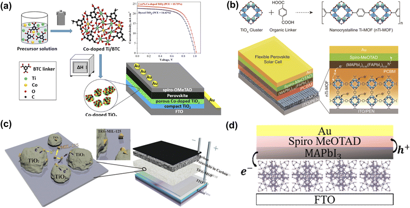 | ||
| Fig. 2 (a) Synthesis of Co-doped TiO2 and schematic diagram of device structure. Reproduced from ref. 55 with permission from the American Chemical Society, copyright 2020. (b) Schematic presentation of the synthetic protocol for nanocrystalline Ti-MOF (nTi-MOF) and device structure of flexible PSCs based on nTi-MOF/PCBM ETL. Reproduced from ref. 48 with permission from the American Chemical Society, copyright 2018. (c) Visualization of the structure of the photoactive MOF@TiO2 composite and the structure of a depleted quasi-bulk heterojunction TiO2-MOF-based solar cell. Reproduced from ref. 56 with permission from the Royal Society of Chemistry, copyright 2014. (d) Depiction of PSC device structure incorporating NH2-MIL-101(Fe). Reproduced from ref. 57 with permission from Elsevier, copyright 2021. | ||
Considering that MOF derivatives have good crystallinity and regular nanostructure, pre-annealing treatment is used to eliminate chemical residues and help improve the stability of solar cells. The large specific surface area and uniform pore network not only facilitate the effective penetration and complete filling of perovskite but also increase the contact area between ETM/perovskite, increase internal light scattering, and promote rapid electron transport. A ZIF-8-derived porous carbon skeleton layer is prepared by carbonizing the ZIF-8 thin film on conducting glass as the electron transport skeleton of PSCs (Fig. 3a).59 Since the good electrical conductivity of ZIF-8-derived porous carbon skeleton, the photo-generated electron transfer rate of PSCs is improved. At the same time, the porous structure of the ZIF-8-derived carbon layer increases the contact area between the perovskite layer and the TiO2 layer, which is beneficial to the separation of photo-generated charges. Therefore, the PCE of MAPbI3 PSCs increased from 14.25% to 17.32%. Subsequently, Liu et al. used titanium-based MOF MIL-125-derived porous anatase nanocrystals (nano-TiO2) as ETM. Through screen printing, Nano-TiO2 can be conveniently covered on the substrate and still maintain the cake-like morphology. Compared with commercial TiO2 (P25), the cake-like morphology composed of nanocrystals is more conducive to the crystallization of perovskite and can reduce the recombination of photo-generated electron–hole pairs, thereby improving device performance (Fig. 3b).47 Since ZnO is inexpensive and abundant in nature reserves, it is one of the widely used ETMs in PSCs. As illustrated in Fig. 3c, Yin et al. used MOF-derived ZnO (MZnO) to improve the light-harvesting ability and optimize the interface contact with perovskite. MZnO with a polyhedral morphology and rich internal porous structure to achieve more efficient electron extraction, lower trapped state density, and electron–hole recombination probability, thus significantly increasing the fill factor (FF) and JSC of the PSCs.45 Recently, Liu et al. utilized a mesoporous nanocrystal TiO2 (M-N-TiO2) derived from 2D Ti- MOFs with increased porosity, bigger diameter, and larger specific surface area (Fig. 3d).46 M-N-TiO2 accelerated the electron extraction process, reducing the carrier recombination rate after passivating the perovskite defects and suppressing recombination losses. The PCE of the target device reached 15.66%, and the FF increased by 74.09%. The above work demonstrates that MOF derivatives can provide diverse options and innovative designs with desirable properties for ETLs of PSCs.
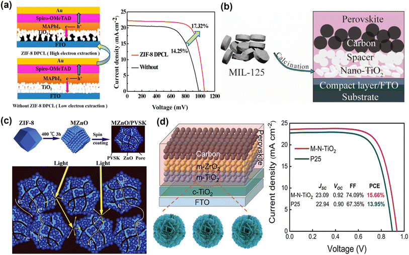 | ||
| Fig. 3 (a) Structure schematic of PSCs with and without the ZIF-8-derived porous carbon layer. Reproduced from ref. 59 with permission from the American Chemical Society, copyright 2019. (b) Application of porous anatase TiO2 nanocrystals in carbon-based PSCs. Reproduced from ref. 47 with permission from the American Chemical Society, copyright 2020. (c) The schematic diagrams of the formation of MOF-Derived ZnO polyhedra and their use as ETL to enhance light harvesting and electron extraction. Reproduced from ref. 45 with permission from Elsevier, copyright 2020. (d) Structure of PM-PSCs, the synthetic process of M-N-TiO2 and J–V curves. Reproduced from ref. 46 with permission from the American Chemical Society, copyright 2023. | ||
3.2. CPMs as or in the hole transport layer
Although the perovskite material has electron–hole bipolar transport characteristics, the choice of HTL as a critical factor in achieving higher PCE cannot be ignored.2 At present, 2,2′,7,7′-tetrakis-(N,N-di-4-methoxyphenylamino)-9,9′-spirobifluorene (Spiro-OMeTAD) has been proven to be the most successful hole transport materials (HTM) in n-i-p PSCs. However, the low intrinsic conductivity and hole mobility of Spiro-OMeTAD limit its applications.63 Both bis(trifluoromethane)sulfonamide lithium salt (LiTFSI) and 4-tert-butylpyridine (t-BP) are doped to improve the charge transport properties of Spiro-OMeTAD. However, they are accompanied by adverse problems such as ion migration, hygroscopicity, and corrosion.64 It is well known that the pore structure of MOF materials is unique, so it has been widely developed and applied to HTL materials for PSCs. Fan et al. report an efficient hybrid polyoxometalate@MOF (POM@Cu-BTC) to promote the oxidation of Spiro-OMeTAD with Li-TFSI and TBP (Fig. 4a). Due to the oxidation activity of POM anions and solid nanoparticles, the doping of POM@Cu-BTC not only promoted the rapid oxidation of Spiro-OMeTAD but also improved the conductivity, more effective carrier extraction, and reduced perovskite/HTM carrier recombination at the interface results in the better long-term stability of unencapsulated devices in ambient atmosphere.60 They also introduced a multifunctional nanostructured host–guest POM@MOF by adjusting the mass loading of H3PMo12O40 in porphyrin-based MOF-545, and controlled oxidation of Spiro-OMeTAD was achieved in an inert environment. The doped devices display high PCE (21.5%) and significant long-term air stability. More importantly, the functionalized POM@MOF with rich active sites serves as an encapsulation layer, effectively restricting the migration and leakage of Pb2+ from the degraded PSCs and preventing possible heavy metal contamination (Fig. 4b).61 Later, they used a highly stable Zn-based MOF (Zn-CBOB) with rod-like topology and Lewis-base sites. The as-prepared Zn-CBOB showed excellent water stability, promoting the oxidation of Spiro-OMeTAD and improved hole mobility and conductivity (Fig. 4c). Therefore, the optimal efficiency of PSCs was increased from 19.14% to 20.64% after doping with Zn-CBOB.62 As shown in Fig. 4d, Zhang et al. constructed a dual-functional layer HTM-FJU-17 by incorporating the (Me2NH2)+-encapsulated indium-based MOF (FJU-17) as a “capsule” into HTM, which simultaneously achieved defect passivation and hole mobility enhancement.39 This work demonstrates the great potential of utilizing bifunctional layers based on bulk anionic MOF/HTMs to fabricate PSCs with high performance and simplified fabrication processes.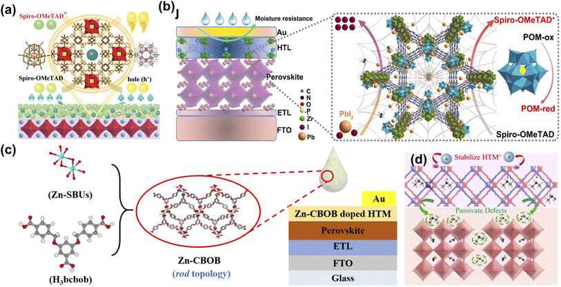 | ||
| Fig. 4 (a) Mechanism diagram of POM@Cu-BTC doping Spiro-OMeTAD as the hole transport layer (HTL). Reproduced from ref. 60 with permission from Wiley-VCH, copyright 2019. (b) The schematic of the positive effects of P@M on the efficiency and stability of devices. Reproduced from ref. 61 with permission from Elsevier, copyright 2022. (c) Schematic diagram of Zn-CBOB synthesis and preparation of Zn-CBOB-doped PSCs. Reproduced from ref. 62 with permission from the American Chemical Society, copyright 2021. (d) Schematic illustration of defect passivation and hole mobility enhancement induced by the HTM-FJU-17. Reproduced from ref. 39 with permission from Elsevier, copyright 2021. | ||
Although the above MOF doping promotes Spiro-OMeTAD oxidation, it does not eliminate Li-TFSI and t-BP. As the only liquid phase component in HTLs of PSCs, t-BP volatilizes quickly to induce the aggregation, hydration, and ion penetration of lithium salts, which seriously affects the thermal stability of the device.67 The strong hygroscopicity of Li-TFSI accelerates the degradation of perovskite films, causing a decline in the long-term stability of PSCs.68 Yang et al. developed a novel thermally stable MOF In-Pyia with active pyridyl sites to substitute volatile t-BP (Fig. 5a). Benefitting from the robust framework and strong coordination effect between pyridine nitrogen atoms and Li+ ions, In-Pyia successfully suppressed morphology deterioration in HTL films. Consequently, replacing t-BP with In-Pyia endows the PSCs with realized enhanced PCE and long-term stability in an ambient environment.65 Subsequently, they constructed a novel dopant Li-TFSI endohedral MOFs (namely Li-TFSI@NH2-MIL-101) to reduce the amount of Li salt and resist the attack of water molecules (Fig. 5b). In addition, the strong interaction between the ammonium group (–NH2) and the uncoordinated Pb2+ ions passivated the trap states and inhibited the migration of the ions at the perovskite/HTL layer, further improving the device's stability.66 Li-TFSI@NH2-MIL-101 doped PSCs exhibit excellent long-term stability due to a significant reduction in the amount of hygroscopic Li-TFSI, retaining more than 85% of the initial PCE aging of 3600 h in the environment without further encapsulation.
 | ||
| Fig. 5 (a) The molecular structures of H2Pyia, t-BP, and their mechanism of action in PSCs. Reproduced from ref. 65 with permission from Elsevier, copyright 2020. (b) Schematic illustration of the synthesis process of Li-TFSI@NH2-MIL-101. Reproduced from ref. 66 with permission from Elsevier, copyright 2022. | ||
Despite the benefits brought by the above doping/replacement strategies, the unstable nature of Spiro-OMeTAD has not changed. As shown in Fig. 6a, Ghorashi et al. synthesized Cu–Ni bimetallic organic frameworks by a simple, stepwise solvothermal method using metal MOF as precursors and sacrificial template. The bimetallic organic framework was calcined in air at 400 °C to obtain CuO@NiO nanospheres with a core–shell structure. Compared with NiO nanospheres, the surface of the core–shell CuO@NiO nanostructure becomes rough, and the diameter of particles increases to 350–400 nm. The optical absorption spectra of the core–shell CuO@NiO show that the maximum absorption wavelength of the core–shell CuO@NiO is red-shifted, resulting in a smaller bandgap than NiO. The CuO shell layer on NiO nanocrystals not only reduces the traps and defect states but also promotes the hole transfer process between the perovskite layer and the CuO@NiO, which ultimately leads to a promising PCE, lower hysteresis, and better long-term stability.51 Distinct from regular n-i-p configurations, PSCs with inverted (p-i-n) configurations further gained popularity owing to their low-temperature processing, high stability, and compatibility with large-scale fabrication. Zou et al. utilized a lifting-up method to transfer a floating film of Ni3(2,3,6,7,10,11-hexaiminotriphenyl)2 (Ni3(HITP)2) of controlled thickness at the gas–liquid interface to an ITO substrate as an ideal dopant-free HTL for PSCs (Fig. 6b). The prepared Ni3(HITP)2 film demonstrates high compactness and uniformity, simultaneously exhibiting high hole extraction capability. The PSCs with Ni3(HITP)2 as a dopant-free HTL achieved a champion PCE reach of 10.3%.54 Yan et al. utilized a convenient self-assembly layer-by-layer growth method to prepare two-dimensional conjugated-MOF (Cu3(HHTT)2 (2,3,7,8,12,13-hexahydroxytetraazanaphthotetraphene, HHTT)) films with large-area uniformity and controllable thicknesses of a few nanometers (Fig. 6c). The expanded π-conjugation of Cu3(HHTT)2 and the embedded heteroatoms in the HHTT ligand favor strong ligand interactions and ordered π–π stacking.
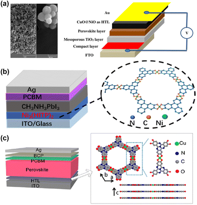 | ||
| Fig. 6 (a) FE-SEM images of CuO@NiO nanosphere and the corresponding device structure. Reproduced from ref. 51 with permission from Springer Nature, copyright 2020. (b) The device structure and the crystal structure of Ni3(HITP)2. Reproduced from ref. 54 with permission from Springer Nature, copyright 2022. (c) Device structure of an inverted PSC and the crystal structure of Cu3(HHTT)2. Reproduced from ref. 53 with permission from American Chemical Society, copyright 2022. | ||
On the other hand, the orbitals of the square-planar Cu2+ ions are energetically well matched to the free radical state ligands, leading to in-plane π-conjugation. These effects endow two-dimensional c-MOF with excellent carrier transport capabilities. The authors also found that the ultra-smooth surface of Cu3(HHTT)2 films facilitates the subsequent growth of perovskite films and passivates defects on the perovskite surface. It is encouraging to note that the PCE of the ideal bandgap PSCs exceeds 22%.53 The work demonstrated that 2D c-MOF is an ideal charge transport material for PSCs, especially for large-area devices.
3.3. CPMs/perovskite heterojunction
The light-absorbing layer is the core of PSCs and is crucial to efficiency and stability. High-quality perovskite films are obtained by modifying the photovoltaic properties of perovskite materials through component engineering. The abundant functional groups of organic ligands or organic monomers in CPMs coordinate with uncoordinated Pb2+, I−, and other groups in the perovskite, thus affecting its crystallization. Ho et al. combined MOF-525 with perovskite by adding MOF-525 microporous nanocrystals as perovskite light-absorbing layer additives, which aggregated near the buried of the MOF/perovskite composite film. The microporous scaffolds provided an orderly arrangement of perovskite microcrystals in the initial stage of crystallization, and the morphology and crystallinity of perovskite films were significantly improved. Thus significantly improving open circuit voltage (VOC) and FF.38 Yang et al. introduced a three-dimensional MOF [In2(phen)3Cl6]·CH3CN·2H2O (In2) into a PbI2 precursor to improve the crystallization and morphology of perovskite films with larger grains and reduced trap states (Fig. 7a). Meanwhile, the recombination of the carrier was inhibited. The PCE exhibited a significant increase from 15.41% to 17.15% and improved the moisture resistance of PSCs.43 Next year, they proposed a simple approach to improve the efficiency and stability of PSCs by combining perovskite with microporous In-based MOF [In12O(OH)16(H2O)5(btc)6]n (In-BTC) nanocrystals to form a heterojunction light-harvesting layer. The interconnected micropores and rich terminal oxygen sites of In-BTC endow the perovskite to crystallize within regular cavities preferentially, imparting improved morphology/crystallinity and reduced grain boundaries/defects to the derived film (Fig. 7b). Due to the optimized interfacial electrical contact and optical response, the PCE based on perovskite/In-BTC heterojunctions exhibited enhanced performance (19.63 ± 1.24%) superior to pristine devices (18.19 ± 1.33%).37 As shown in Fig. 7c, Fan et al. achieved efficient and stable grain passivation in perovskite films by preparing formic acid-functionalized 2D Zn-based MOF Zn-cbpp ([Zn(cbpp)(HCOO)]n, Hcbpp = 1-[4-carboxylbenzyl]-3-[pyrzin-2-yl]pyrazole) as terminators. Through the strong interaction between the exposed active sites and PbI2, Zn-cbpp tightly covers the surface of PbI2-terminated perovskite grains to stabilize the perovskite phase and facilitate the adhesion of adjacent grains. Benefitting from the decreased defect density, suppressed charge recombination, and faster charge extraction, the champion PCE of PSCs improved from 19.59% to 21.28%.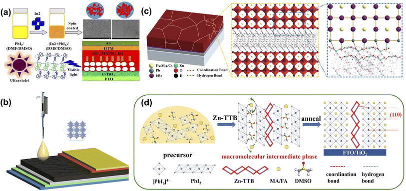 | ||
| Fig. 7 (a) The design concept and device structure of [In0.5K(3-qlc)Cl1.5(H2O)0.5]2n. Reproduced from ref. 43 with permission from Elsevier, copyright 2019. (b) The schematic diagram for fabricating n-i-p PSCs with the perovskite/In-BTC heterojunction as a light-harvesting layer. Reproduced from ref. 37 with permission from Springer Nature, copyright 2020. (c) Schematic illustration of the perovskite film with Zn-cbpp modification. Reproduced from ref. 44 with permission from Wiley-VCH, copyright 2021. (d) Schematic illustration of the Zn-TTB-regulated grain growth process by inducing a macromolecular intermediate phase. Reproduced from ref. 69 with permission from Wiley-VCH, copyright 2022. | ||
Meanwhile, the moisture and thermal stability of the corresponding PSCs were significantly improved due to the Zn-cbpp modification that inhibited water intrusion and mitigated the decomposition and phase transition of the perovskite film under heating.44 Yang et al. constructed another Zn-based MOF Zn-TTB, self-assembled from Zn2+ and 1-(triazole-1-ly-4-tetrazol-5-ylmethyl)benzene (TTB), inheriting and arranging triazole and tetrazole moieties to form long chain structures around metal nodes. As the additive to perovskite precursor, the Zn-TTB backbone grows with perovskite crystal and generates a macromolecular intermediate phase via MOFs/perovskite heterojunction, followed by the formation of superior perovskite films (Fig. 7d). The MOF-doping increased the degradation activation energies by up to 174.01 kJ mol−1; thus, Zn-TTB-modified PSCs exhibited promised operational stability.69 These works have demonstrated the potential of In and Zn-based MOFs to inspire the precise construction of MOF additives for high-performance photovoltaic devices.
In addition to the In and Zn-based MOFs, Chueh et al. investigated two Zr-MOFs (UiO-66 and MOF-808) with comparable humidity and chemical stability. It was found that the perovskite/Zr-MOF hybrid heterojunction could be distributed on the perovskite grain boundaries, providing a grain-locking effect while passivating defects and enhancing the stability of the film to resist water intrusion. The PCEs of the UiO-66/MOF-808-hybrid PSCs could be further enhanced to 18.01% and 17.81%, respectively (Fig. 8a). More interestingly, more than 70% of the initial PCE was retained after storage in ambient air (25 °C and 60 ± 5% relative humidity) for more than 2 weeks compared to the rapid degradation of the pristine device.70 Yang et al. constructed two MOFs (Cd-Httb and Cd-Httb-BDC, Httb = 5-(4-(1H-1,2,4-triazole-1-yl)benzyl)-1h-tetrazole, BDC = 1,4-dicarboxybenzene) with tunable Lewis-base passivation sites to eliminate deep-level defects while acting as nonhomogeneous nucleation seeds of the nanostructures to aid in the growth of large-grained perovskite films. Cd-Httb-BDC designed with a mixed ligand strategy showed enhanced induction of crystallization and nucleation of high-quality perovskite films during the annealing process compared to control and Cd-Httb (Fig. 8b). Consequently, Cd-Httb-BDC modified PSCs achieved a PCE of 22.18% with a higher VOC of 1.182 V. Cd-Httb-BDC can also prevent moisture intrusion and phase separation and significantly improve the stability of PSCs.71 As shown in Fig. 8c, Kang et al. hybridized hygroscopic copper(II) benzene-1,3,5-tricarboxylate MOFs (Cu-BTC) with light-absorbing perovskite layers for polyvinyl chloride, where Cu-BTC MOFs moderate moisture is attracted during the synthesis step, resulting in enhanced perovskite crystallization.
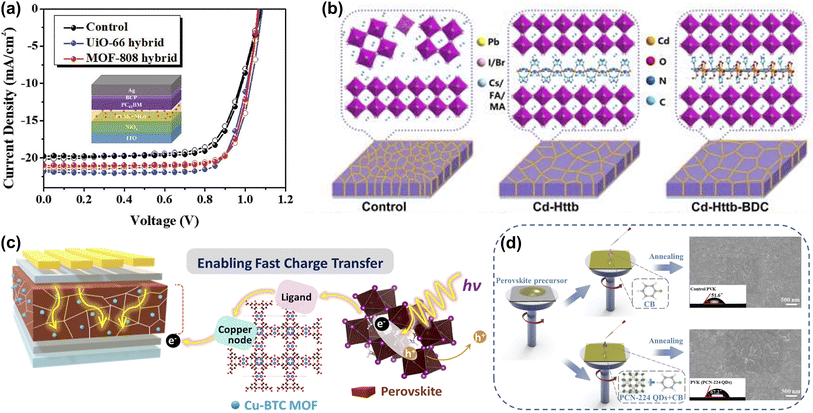 | ||
| Fig. 8 (a) The J–V curves of the UiO-66 and MOF-808 modified devices. Reproduced from ref. 70 with permission from Wiley-VCH, copyright 2019. (b) Schematic diagram of Cd-Httb and Cd-Httb-BDC as a structural guide to regulate ordered growth of perovskite film. Reproduced from ref. 71 with permission from Elsevier, copyright 2022. (c) Schematic illustration of Cu-BTC for fast charge transport and high stability of light-absorbing perovskite hybrid layer in PSCs. Reproduced from ref. 42 with permission from American Chemical Society, copyright 2022. (d) A schematic diagram of the PCN-224 QDs assisted perovskite crystallization through a one-step antisolvent process. The top-view SEM images of perovskite films and the images of water droplet contact angles on different surfaces are presented simultaneously. Reproduced from ref. 41 with permission from Wiley-VCH, copyright 2023. | ||
Meanwhile, the perovskite-MOF heterojunction facilitates the transfer of photoexcited electrons from perovskite to TiO2 by providing additional electron extraction channels. Based on the above advantages, PSCs achieved a PCE of 20.5% and high humidity stability.42 Wang et al. developed an effective strategy to simultaneously address the humidity, thermal, and light-soaking stability of PSCs using ultrasmall PCN-224 quantum dots (a typical Zr-based porphyrinic MOF) that were successfully prepared from larger nanoparticles by an ultrasonic cell disruption system. PCN-224 with rich Lewis-base groups were dissolved in CB with the simultaneous introduction of perovskite and HTL layers (Fig. 8d). Not only does PCN-224 increase grain size and reduce defect density by interacting with undercoordinated Pb2+, but it also captures Li+, leading to a reduction in hygroscopic Li-TFSI aggregation. This dual-function strategy significantly improves device durability.41
Unlike MOFs, which are porous materials formed by coordinated metal ions/clusters, COFs are two- or three-dimensional porous materials self-assembled by covalent bonds through light elements (i.e., H, B, C, N, O). COFs linked by high-energy covalent bonds are generally more chemically stable, and the vanishing metals are more sustainable and environmentally compatible.26 Wang et al. synthesized for the first-time two-dimensional COF nanosheets [(TPA)1(TPhT)1]–C![[double bond, length as m-dash]](https://www.rsc.org/images/entities/char_e001.gif) N–in situ in a PbI2 layer with a highly crystalline structure to precisely regulate the crystallization process of perovskite by a two-step sequential deposition. The presence of two-dimensional COF nanosheets slows down the intermolecular interdiffusion and induces the growth of perovskite crystals along the (110) plane with an increase in grain size. Meanwhile, the COF is distributed around the perovskite grain boundaries, reducing defect density and promoting carrier transport (Fig. 9a). The excellent performance of the perovskite thin film enabled the champion PSC to increase the PCE by more than 10% over the control device, and the target PSC also exhibited outstanding long-term stability.72 As shown in Fig. 9b, Tang et al. demonstrate a generalized grain ‘caging’ approach to obtain highly efficient and phase-stable wide-bandgap PSCs by incorporating monomer molecules into the perovskite precursor to form organic COFs in situ on the perovskite surface and grain boundaries. Under the catalysis of PbX2, COFs are chemically bonded with the perovskite lattice, which simultaneously suppresses halide segregation and passivate defects due to the increase in ion migration activation energy and vacancy formation energy. As a result, the champion PCE of carbon electrode-based all-inorganic CsPbIBr2 and CsPbI2Br PSCs are 11.50% and 14.35%, respectively. They also have excellent long-term stability against humidity, thermal, and light-soaking.73 HOFs are novel porous crystalline materials that self-assemble discrete organic molecules through intermolecular hydrogen bonding interactions, and the inherent characteristics of hydrogen bonding connections (weak, flexible, poorly oriented, and reversible) imply that HOFs differ from MOFs and COFs in several interesting ways, such as mild synthesis conditions, solution processability, and ease of healing and regeneration and other unique features.28 Zhang et al. introduced a bicarbazole molecule featuring cyanogroup into perovskite precursors, based on the easy aggregation characteristics the monomer self-assembled into an ordered porous framework structure in GB. Besides defect passivation, moisture barrier and crystallization-promoting abilities, the ordered porous stacking structures offer additional advantages in releasing residual stresses and suppressing metallic Pb leakage. Consequently, the optimal PCE of the target device reached 23.15%, and the thermal and operational stability of the PSCs were significantly improved with reduced Pb2+ leakage (Fig. 9c).74
N–in situ in a PbI2 layer with a highly crystalline structure to precisely regulate the crystallization process of perovskite by a two-step sequential deposition. The presence of two-dimensional COF nanosheets slows down the intermolecular interdiffusion and induces the growth of perovskite crystals along the (110) plane with an increase in grain size. Meanwhile, the COF is distributed around the perovskite grain boundaries, reducing defect density and promoting carrier transport (Fig. 9a). The excellent performance of the perovskite thin film enabled the champion PSC to increase the PCE by more than 10% over the control device, and the target PSC also exhibited outstanding long-term stability.72 As shown in Fig. 9b, Tang et al. demonstrate a generalized grain ‘caging’ approach to obtain highly efficient and phase-stable wide-bandgap PSCs by incorporating monomer molecules into the perovskite precursor to form organic COFs in situ on the perovskite surface and grain boundaries. Under the catalysis of PbX2, COFs are chemically bonded with the perovskite lattice, which simultaneously suppresses halide segregation and passivate defects due to the increase in ion migration activation energy and vacancy formation energy. As a result, the champion PCE of carbon electrode-based all-inorganic CsPbIBr2 and CsPbI2Br PSCs are 11.50% and 14.35%, respectively. They also have excellent long-term stability against humidity, thermal, and light-soaking.73 HOFs are novel porous crystalline materials that self-assemble discrete organic molecules through intermolecular hydrogen bonding interactions, and the inherent characteristics of hydrogen bonding connections (weak, flexible, poorly oriented, and reversible) imply that HOFs differ from MOFs and COFs in several interesting ways, such as mild synthesis conditions, solution processability, and ease of healing and regeneration and other unique features.28 Zhang et al. introduced a bicarbazole molecule featuring cyanogroup into perovskite precursors, based on the easy aggregation characteristics the monomer self-assembled into an ordered porous framework structure in GB. Besides defect passivation, moisture barrier and crystallization-promoting abilities, the ordered porous stacking structures offer additional advantages in releasing residual stresses and suppressing metallic Pb leakage. Consequently, the optimal PCE of the target device reached 23.15%, and the thermal and operational stability of the PSCs were significantly improved with reduced Pb2+ leakage (Fig. 9c).74
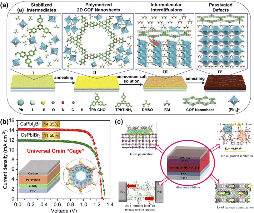 | ||
| Fig. 9 (a) Illustrates the role of 2D COF nanosheets in preparing high-quality perovskite films in the sequential deposition method. Reproduced from ref. 72 with permission from Wiley-VCH, copyright 2022. (b) The crystal structure of 2D conjugated COF, the prepared device structure, and the J–V curve. Reproduced from ref. 73 with permission from American Chemical Society, copyright 2022. (c) The mechanism of HOF-FJU-1 in PSCs. Reproduced from ref. 74 with permission from Elsevier, copyright 2023. | ||
3.4. CPMs as the perovskite/ETL interfacial layer
The energy level matching between ETL and perovskite layer is crucial to improve the extraction and collection efficiency of carriers and the VOC of the device. TiO2 is an n-type semiconductor material with high optical transparency, energy level matching with perovskite, and tunable electronic properties, and it is widely used as the ETL in PSCs.78 Despite the many advantages of TiO2 as an ETL, low electrical conductivity, electron mobility, and many oxygen vacancy defects generated on the surface after high-temperature sintering limited its further utilization.79 ZIF-8 is a three-dimensional porous crystal bridged by tetrahedral Zn ions with 2-methylimidazole as the ligand. Due to its high crystallinity, high surface area, chemical, and thermal stability, it has been widely used in various applications.80 Wei et al. first studied the modification of mp-TiO2 films with ZIF-8 layers, which can significantly improve the crystallinity and morphology of perovskite films. The interface between mp-TiO2/ZIF-8 and the perovskite film effectively inhibited the recombination of photo-generated carriers and improved charge extraction (Fig. 10a). As a result, the champion PCE of PSCs improved to 16.99%.75 Eslamian et al. applied ZIF-8 to the interface of compact TiO2 (c-TiO2) and perovskite to fabricate mesoporous-TiO2(m-TiO2)-free PSC and replaced the commonly used thermal annealing process with room-temperature ultrasonic vibratory treatment of wet perovskite films (Fig. 10b). The results showed that ZIF-8 can effectively modify the interface between c-TiO2 and perovskite and reduce the recombination of carriers, thus improving the PCE of PSCs. ZIF-8 can be easily synthesized and cast at low temperatures, and its replacement with m-TiO2 can significantly reduce energy consumption.49 As illustrated in Fig. 10c, Chen et al. utilized a thermally stable ZIF-8 as an encapsulating agent to encapsulate ammonium iodide (FAI) and construct a multifunctional layer between the SnO2 and the PbI2 layer. Introducing ZIF-8@FAI capsules increased hole transport channels in the PbI2 layer, promoting the penetration of the organic cation solution components and significantly reducing the PbI2 residue. In addition, the predetermined precursor composition wrapped in the capsule benefits the nucleation of perovskite and promotes the formation of perovskite films with large grain size, low trap density, and superior vertical orientation. Meanwhile, the abundant imidazolium-nitrogen sites effectively passivated the uncoordinated Pb2+ defects and mitigated the residual tensile strain in the perovskite film. Consequently, the modified PSCs achieved 24.08% champion performance with significant ultraviolet resistance.76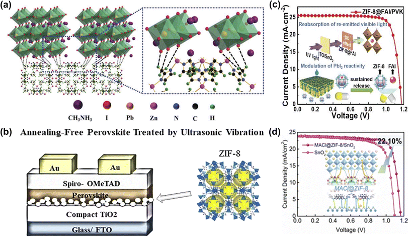 | ||
| Fig. 10 (a) Schematic illustration of two neighboring grain structures cross-linked by methyl groups of ZIF-8. Reproduced from ref. 75 with permission from the Royal Society of Chemistry, copyright 2018. (b) Steady-state PL spectra, the crystal structure of ZIF-8, and the schematic diagram of the prepared PSC. Reproduced from ref. 49 with permission from the American Chemical Society, copyright 2020. (c) Schematic diagram of ZIF-8@FAI capsules modulates reactivity of PbI2 toward efficient PSCs with ultraviolet resistance. Reproduced from ref. 76 with permission from Wiley-VCH, copyright 2023. (d) Schematic diagram of the mechanism of MACl@ZIF-8 between perovskite and SnO2. Reproduced from ref. 77 with permission from the Royal Society of Chemistry, copyright 2023. | ||
Recently, Rui et al. utilized ZIF-8-loaded ammonium salt to modify the SnO2/perovskite interface. MACl@ZIF-8 not only effectively reduces the oxygen vacancies on the SnO2 surface but also binds with the uncoordinated Pb2+ and halogen ions in the bottom of the perovskite layer (Fig. 10d). Meanwhile, due to the UV-resistant property of ZIF-8 and the double passivation of the host and guest groups, the UV stability and humidity stability of the device are more prominent than that of the control device.77 Consequently, the CPMs confined ammonium salts presented in these works provide innovative perspectives and effective methods for buried interface passivation and even other aspects of device defect management.
To reduce the interface carrier loss, Li et al. prepared a PEIE and telluride-phenyl-based two-dimensional MOF composite modified film on the TiO2 surface to improve the morphology and crystallinity of the perovskite film and achieve non-destructive passivation of the interface (Fig. 11a). The efficiency of PEIE-2D MOF-modified PSCs increased from 20.42% to 22.22%.81 As shown in Fig. 11b, Chen et al. introduced an ultra-thin Eu-MOF layer at the interface between the electron transport layer and the perovskite absorber. Eu ions and organic ligands can reduce the defect concentration and promote carrier transport through chemical reactions or coordination interactions. Due to its unique optical properties, Eu-MOF can increase the light absorption range. Meanwhile, Eu-MOF can guide film growth at the buried interface and convert residual tensile strain into compressive strain in the perovskite film. The results show that the photovoltaic conversion efficiency of the device reaches 22.16% by in situ molding of the Eu-MOF layer, as well as better stability against moisture, thermal, and light immersion.82 Borhani Zarandi et al. introduced the HKUST-1 thin films as the interfacial layer of ETL (Fig. 11c). The HKUST-1 particles they synthesized have a hemispherical porous structure with good surface coverage and can form dense interfacial contacts with the perovskite layer, which helped improve light absorption, promote electron extraction, and reduce carrier recombination. With this simple interfacial modification, the PCE of the target PSC was increased by more than 22% with negligible hysteresis behavior and maintained 65% of the initial efficiency over 600 h, resulting in enhanced ambient stability.83 Ho et al. constructed a new type of lead-containing MOF (Pb-MOF) through the postmetalation of MOF-525. The post-metalation strategy could combine the Pb2+ ions with the organic linkers in MOF-525, a scaffolding layer to promote perovskite crystallization (Fig. 11d). Pre-filling of Pb ions in Pb-MOF prevents crystal vacancies and passivates defects while increasing the crystallinity of perovskite and facilitating the injection of electrons from the perovskite layer into ETLs. Since the crystal structure of MOF-525 remains unchanged after metallization, there is no negative impact.50 As shown in Fig. 11e, Kuo et al. successfully developed a two-dimensional conjugated covalent organic framework (2D-COF) based on the tetraphenylethylene building block, which has excellent charge transport capabilities due to its good conjugation properties and π–π interactions. The porous nature can promote perovskite nucleation and crystal growth, potentially reducing charge recombination at the interface due to defect states. As a result, the performance of COF-modified PSCs can be improved from 17.40% to 19.80%. Furthermore, they demonstrate that the energy levels of the derived COFs can be customized by the constituent units, which highlights the importance of structural design in influencing the resulting photovoltaic parameters.84
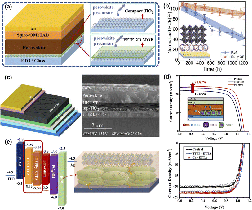 | ||
| Fig. 11 (a) Schematic diagram of the structures of PSCs with and without the PEIE-2D MOF modified layer. Reproduced from ref. 81 with permission from the Royal Society of Chemistry, copyright 2021. (b) Schematic illustration of the Eu-MOF effect on perovskite film and J–V curve. Reproduced from ref. 82 with permission from Wiley-VCH, copyright 2021. (c) Structural schematic and cross-section SEM image of the PSC with HKUST-1 interface layer between the perovskite and mp-TiO2 layer. Reproduced from ref. 83 with permission from Elsevier, copyright 2021. (d) Proposed mechanism for Pb-MOF to explain the improvement in charge transfer and J–V curve. Reproduced from ref. 50 with permission from the American Chemical Society, copyright 2021. (e) The energy-level diagram, schematic illustration of the studied PVSCs, and J–V curve of COF modified sample. Reproduced from ref. 84 with permission from the Royal Society of Chemistry, copyright 2020. | ||
3.5. CPMs as the perovskite/HTL interfacial layer
To improve the conductivity and hole transport properties of HTLs, using an interface layer between HTLs and the perovskite layer not only helps minimize the energy loss caused by the energy level mismatch but also blocks the electrons and facilitates the hole transport process. Metal oxides are widely used as interface layers between perovskite layers and p-type materials to facilitate charge transfer and mitigate charge recombination.89 Bark et al. applied MOF as a template to prepare high-porosity NiO@C nanoparticles, which serve as an interface modification layer between perovskite and Spiro-OMeTAD, to reduce perovskite surface defects and improve charge transfer efficiency, thereby improving the performance of PSCs (Fig. 12a).85 Due to the poor thermal stability of MA or FA, methylamine (MA+) or formamidine (FA+) ion vacancies exist on the surface at high temperatures, even in state-of-the-art PSCs, leading to perovskite degradation and device instability. Therefore, it is crucial to passivate cation vacancies and further slow the evaporation of organic components. As shown in Fig. 12b, Zhang et al. encapsulated the perovskite component methylammonium iodide (MAI) or formamidinium iodide (FAI) in the channels of ZIF-8 by soaking, then used ZIF-8 loaded ammonium iodide salt (ZIF-8@MAI or ZIF-8@FAI) as a multi-functional ‘capsule’ at the perovskite/HTL interface, where the ammonium iodide in the pores was slowly released into the perovskite layer to compensate the vacancies and lower the trap density, and the ZIF-8 prevented evaporation of the organic components of the perovskite, blocking the invasion of water, which enhances the stability of the PSCs.86 Subsequently, Zhang et al. introduced an anionic MOF (ZnL) containing amine counterions and dense oxygen sites on the skeleton on the surface of perovskite and investigated the interaction mechanism between the MOF and perovskite in detail. The results showed that the [(Me2NH2)3(SO4)]+ cation passivated the ionic defects by binding to I− on the perovskite surface through hydrogen bonding. The large number of oxygen sites in the high-density carboxyl groups on the anionic skeleton can form strong electrostatic interactions with the calixarenes, anchoring the atoms in the perovskite and regulating the crystallization of the perovskite. In addition, the porous structure of ZnL can absorb diffused metal atoms, which hinders the diffusion of metal electrode atoms into the perovskite in addition to improving the hydrophobic angle (Fig. 12c). As a result, the PCE of the ZnL-modified device was improved from 19.75% to 21.15% with enhanced stability. This work demonstrates the feasibility of anionic MOFs as multi-functional surface treatment materials in passivating defects, promoting perovskite crystallization and blocking water/metal electrode intrusion.87 Carbon-based CsPbI2Br PSCs have the advantages of high stability and low cost, but poor contact with the perovskite layer and energy mismatch leads to low PCE.90 Xie et al. utilized UV-Ozone irradiation Fe3O4@NC composite (Fe3O4@NC UVO) as the interface layer between the perovskite layer and carbon electrode, which acquired a denser perovskite film and effectively promoted carrier separation (Fig. 12d). As a result, the Fe3O4@NC UVO device achieved a champion PCE of 12.25%, which was a 19.3% improvement over the control PSCs.88 This work offers a straightforward and efficient approach for improving the photovoltaic efficiency and stability of all-inorganic carbon-based CsPbI2Br PSCs.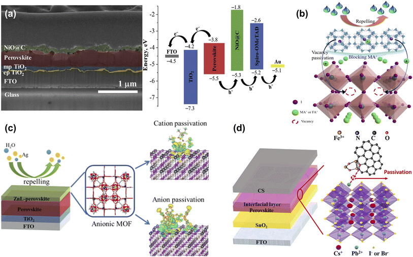 | ||
| Fig. 12 (a) Cross-sectional image of FTO/cp-TiO2/mp-TiO2/perovskite/NiO@C structure and energy level diagram of corresponding PSCs. Reproduced from ref. 85 with permission from Elsevier, copyright 2020. (b) Schematic illustration of the effect of ZIF-8@FAI capsule on perovskite. Reproduced from ref. 86 with permission from the Royal Society of Chemistry, copyright 2021. (c) The crystal structure and mechanism of ZnL-MOF. Reproduced from ref. 87 with permission from Elsevier, copyright 2022. (d) Structure diagram of carbon-based CsPbI2Br PSC with Fe3O4@NC interfacial layer. Reproduced from ref. 88 with permission from Elsevier, copyright 2023. | ||
3.6. CPMs as the electrode or in the interfacial layer
ITO is one of the most commonly used transparent metal oxides (TCOs) but is encumbered by fragility, resource scarcity, and extended manufacturing durations. At the same time, the deposition of TCOs is based on high-energy vacuum deposition techniques, so it is of great significance to develop solution-processed transparent electrodes with good processability and high flexibility. Wang et al. employed a novel type of copper bis(dithiophene) complex (Cu-BHT, the chemical formula is [Cu3(C6S6)]n) with ultra-high conductivity and excellent transparency to prepare Cu-BHT film as the transparent electrode. Cu-BHT replaced the traditionally used ITO electrode and prepared PSCs with comparable performance, demonstrating the great potential of Cu-BHT electrodes in the field of flexible optoelectronics (Fig. 13a).91 Zhang et al. used ZIF-67 as a sacrificial template to prepare nitrogen-containing porous carbon Co-NC (HCl) composite materials. Adding Co-NC (HCl) to conductive carbon paste can effectively improve the interfacial properties of perovskite/carbon electrodes, inhibit charge recombination, and promote hole extraction, thus improving the photovoltaic performance and long-term stability of PSC(Fig. 13b).52 Chen et al. developed a ‘two-in-one’ molecular design strategy to prepare highly crystalline and porous Py-COF. Highly crystalline Py-COF films can be prepared on various substrates, showing potential hole transport properties in PSCs (Fig. 13c).92 Despite the excellent PCE of PSCs, Pb2+ toxicity is a major shortcoming. Variety works proposed strategies to prevent Pb2+ ions leakages, such as physical encapsulation, chemical adsorption, environmentally friendly perovskite materials, and material recycling.94 As shown in Fig. 13d, The dense functional sites around the pores of CPMs have the potential to capture heavy metal ions (such as Pb2+ ions, mercury, and so on). Jen et al. used thiol-functionalized Zr-based two-dimensional conjugated MOF (ZrL3) at the perovskite/cathode interface to adsorb leaked Pb2+. This reduced Pb leakage was attributed to the dense thiol and disulfide groups on ZrL3 form water-insoluble Pb(II)-ZrL3 complexes through chemical reactions with leaking Pb2+ ions. Consequently, the prepared inverted PSCs not only achieved a PCE of 22.02% but also possessed excellent long-term operational stability.93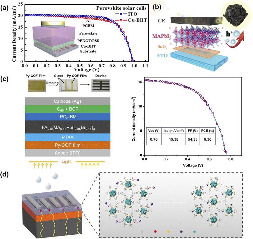 | ||
| Fig. 13 (a) J–V characteristics of the fabricated PSCs with ITO and Cu-BHT electrodes on a glass substrate. Reproduced from ref. 91 with permission from Elsevier, copyright 2017. (b) The illustration of the energy level in HTM-free Co-NC(HCl) mixed CC-PSCs. Reproduced from ref. 52 with permission from Elsevier, copyright 2020. (c) The schematic illustration of the Py-COF film-modified ITO-based device fabrication process. Reproduced from ref. 92 with permission from the American Chemical Society, copyright 2019. (d) Schematic of the degradation process of PSCs and the immobilization effect of ZrL3 on leaked Pb2+ ions. Reproduced from ref. 93 with permission from Springer Nature, copyright 2020. | ||
4. Data mining of the literature and perspectives
As an equally fast-developing system in the current materials field, embedding CPMs into PSCs is a mutually beneficial marriage that has received increasing attention in recent years (Fig. 14a). Like other functional materials (such as Lewis bases, ammonium salts, etc.), CPMs can not only passivate defects and inhibit carrier recombination. Due to their easy modification of pore properties, high conjugation of the skeleton, and ultra-high conductivity, CPMs also have the characteristics of in situ adsorption of Pb2+ ions, filter UV light, and serve as transparent electrodes. As multifunctional platforms, CPMs show great promise in PSCs. To grasp the state-of-the-art development overview of CPM-based PSCs, we summarized Table 1 based on the above discussion and classified the types of CPMs at different functional layers, as well as the impact of different types of CPMs on performance. As seen from the pie chart in Fig. 1f, MOFs account for 90% of the total research works due to the maturity of MOFs in both laboratory and industry. Therefore, they are classified according to different metal sites during discussion. | ||
| Fig. 14 (a) Number of publications per year involving applications of CPMs to PSCs. (b) The percentages of three CPMs. Composition of CPMs-based PSCs by summating the parameters in Table 1. | ||
| CPM type | Role | Name | Metal site | Perovskite | V OC (V) | J SC (mA cm−2) | FF (%) | PCE (%) | PCE improvement ratio (%) | Ref. |
|---|---|---|---|---|---|---|---|---|---|---|
| MOF | ETL | Co-doped Ti-MOFs | Ti | MAxFA1−xPb(BryI1−y)3 | 1.027 | 24.08 | 64.95 | 15.75 | 27.84 | 55 |
| MOF | ETL | nTi-MOF | Ti | (MAPbI3)0.95(FAPbI3)0.05 | 1.082 | 23.18 | 75.5 | 18.94 | 15.42 | 48 |
| MOF | ETL | MIL-125 | Ti | MAPbI3 | 0.85 | 10.9 | 69.00 | 6.40 | 156.00 | 56 |
| MOF | ETL | NH2-MIL-125(Fe) | Ti | MAPbI3 | 0.68 | 12.29 | 48 | 4.1 | — | 57 |
| MOF | ETL | ZIF-8 DPCL | Zn | MAPbI3 | 1.06 | 22.13 | 72 | 17.32 | 21.54 | 59 |
| MOF | ETL | MIL-125 | Ti | (5-AVA)x(MA)1−xPbI3 | 0.907 | 21.83 | 68.14 | 13.42 | 29.29 | 47 |
| MOF | ETL | MZnO | Zn | CsxFA1−xPb(BryI1-y)3 | 1.11 | 22.1 | 73.9 | 18.1 | 19.87 | 45 |
| MOF | ETL | M-N-TiO2 | Zn | — | 0.92 | 23.09 | 74.09 | 15.66 | 12.26 | 46 |
| MOF | ETL | ZnO/C | Ti | MAPbI3−xClx | 1.14 | 22.9 | 70 | 19.6 | 29.80 | 95 |
| MOF | ETL | MIL-125 (Ti) | Ti | MAPbI3 | 1.01 | 22.81 | 71.84 | 16.56 | 45.52 | 96 |
| MOF | ETL | MIL-125 (Ti) | Ti | MAPbI3 | 1.03 | 13.91 | 74.11 | 18.25 | 16.69 | 97 |
| MOF | HTL | POM@MOF | Cu | Cs0.1FA0.747MA0.153PbI2.49Br0.51 | 1.11 | 23.90 | 80 | 21.44 | 6.09 | 60 |
| MOF | HTL | P@Ms | Zr | Cs0.1FA0.747MA0.153PbI2.49Br0.51 | 1.11 | 24.1 | 80 | 21.5 | 6.97 | 61 |
| MOF | HTL | Zn-CBOB | Zn | CsFAMA | 1.135 | 23.18 | 78.4 | 20.64 | 7.84 | 62 |
| MOF | HTL | FJU-17 | In | MAPbI3 | 1.05 | 25.09 | 77 | 20.34 | 11.03 | 39 |
| MOF | HTL | In-Pyia | In | Cs0.05FA0.81MA0.14PbI2.55Br0.45 | 1.09 | 23.53 | 79 | 20.26 | 9.87 | 65 |
| MOF | HTL | NH2-MIL-101 | Fe | Cs0.05FA0.81MA0.14PbI2.55Br0.45 | 1.073 | 23.41 | 75.77 | 19.01 | −1.14 | 66 |
| MOF | HTL | CuO@NiO | Cu | MAPbI3 | 0.91 | 21.80 | 51 | 10.11 | 17.83 | 51 |
| MOF | HTL | Ni3(HITP)2 | Ni | — | 0.91 | 17.09 | 66 | 10.3 | — | 54 |
| MOF | HTL | Cu3(HHTT)2 | Cu | Pb–Sn mixed | 0.92 | 30.13 | 79.42 | 22.01 | 9.12 | 53 |
| MOF | HTL | [In0.5K(3-qlc)Cl1.5(H2O)0.5]2n | In | MAxFA1−xPb(BryI1−y)3 | 1.00 | 24.3 | 70 | 17.0 | 20.57 | 98 |
| MOF | HTL | [In2(phen)3Cl6]·CH3CN·2H2O | In | MAPbI3 | 1.01 | 21.03 | 74 | 15.8 | 23.44 | 99 |
| MOF | HTL | NPC | In | Cs0.05FA0.81MA0.14PbI2.55Br0.45 | 1.06 | 23.51 | 76 | 18.51 | 12.39 | 100 |
| MOF | HTL | Pb-MOF | Pb | MAPbI3 | 1.00 | 19.57 | 67.30 | 13.17 | 25.07 | 40 |
| MOF | HTL | MIL-88B-1,3-SO3H | Cr | CsFAMA | 1.18 | 24.07 | 79 | 22.44 | 14.49 | 101 |
| MOF | HTL | NiOx NPs | Ni | — | 1.89 | 11.07 | 66.6 | 13.9 | — | 102 |
| MOF | PVSK | In-BTC | In | Cs0.05FA0.81MA0.14PbI2.55Br0.45 | 1.12 | 23.55 | 79 | 20.87 | 6.92 | 37 |
| MOF | PVSK | Zn-cbpp | Zn | MAxFA1−xPb(BryI1−y)3 | 1.155 | 23.32 | 79 | 21.28 | 8.63 | 44 |
| MOF | PVSK | Zn-TTB | Zn | Cs0.05FA0.85MA0.10Pb(I0.97Br0.03)3 | 1.148 | 25.16 | 80.1 | 23.14 | 7.93 | 69 |
| MOF | PVSK | MOF-525 | Zr | MAPbI3 | 0.93 | 23.04 | 60 | 12.0 | 18.81 | 38 |
| MOF | PVSK | [In2(phen)3Cl6] CH3CN·2H2O | In | MAPbI3 | 1.04 | 23.18 | 0.71 | 17.15 | 11.29 | 43 |
| MOF | PVSK | UiO-66-NH2 | Zr | MASn0.25Pb0.75I3 | 0.75 | 25.73 | 72.29 | 13.93 | — | 70 |
| MOF | PVSK | UiO-66 | Zr | MAPbI3 | 1.07 | 21.85 | 76.9 | 17.81 | 12.79 | 70 |
| MOF | PVSK | MOF-808 | Zr | MAPbI3 | 1.06 | 21.01 | 79.8 | 18.01 | 14.06 | 70 |
| MOF | PVSK | Cd-Httb-BDC | Cd | Cs0.1FA0.747MA0.153PbI2.49Br0.51 | 1.182 | 24.25 | 77.4 | 22.18 | 6.18 | 71 |
| MOF | PVSK | Cu-BTC | Cu | MAxFA1−xPb(BryI1−y)3 | 1.13 | 22.8 | 79 | 20.5 | 11.41 | 42 |
| MOF | PVSK | PCN-224 QDs | Zr | Cs0.05MA0.16FA0.79Pb(I0.83Br0.17)3 | 1.172 | 24.56 | 78.21 | 22.51 | 17.92 | 41 |
| COF | PVSK | [(TPA)1(TPhT)1]–C![[double bond, length as m-dash]](https://www.rsc.org/images/entities/char_e001.gif) N– N– |
— | FAPbI3 | 1.112 | 24.92 | 79.6 | 22.04 | 10.14 | 72 |
| COF | PVSK | TAPT/BPDA | — | CsPbI2Br | 1.327 | 11.95 | 72.55 | 11.50 | 31.13 | 73 |
| HOF | PVSK | HOF-FJU-1 | — | Cs0.05(FA0.95MA0.05)0.95Pb(I0.95Br0.05)3 | 1.135 | 24.78 | 82.29 | 23.15 | 10.24 | 74 |
| MOF | PVSK | CoW12@MIL-101 | Cr | CsFAMA | 1.135 | 23.85 | 79 | 21.39 | 10.20 | 103 |
| MOF | PVSK | Cr-MOF | Cr | CsPbI2Br | 1.30 | 16.51 | 79 | 17.02 | 17.95 | 104 |
| MOF | PVSK | Zn(II) LH2 | Zn | — | 0.96 | 9.36 | 62 | 5.64 | 91.19 | 105 |
| MOF | PVSK | UIO-66 | Zr | MAPb(IyCl1−y)3 | 1.190 | 24.16 | 80.19 | 23.05 | 10.66 | 106 |
| MOF | PVSK | POMOF | Zn | (FAPbI3)0.93(MAPbBr3)0.04(CsPbI3)0.03 | 1.194 | 25.03 | 78.0 | 23.3 | 7.67 | 107 |
| MOF | PVSK | MOF-235 | Fe | MAPbI3 | 1.03 | 14.09 | 65 | 9.56 | 14.63 | 108 |
| MOF | PVSK | Tb-cpon | Tb | Cs0.05FA0.85MA0.10Pb(I0.97Br0.03)3 | 1.155 | 25.35 | 81.0 | 23.72 | 10.53 | 109 |
| MOF | PVSK | UiO-66-(SH)2 | Zr | FAMA | 1.184 | 25.21 | 80.71 | 24.09 | 7.11 | 110 |
| COF | PVSK | DA-COF-2 | — | FAPbI3 | 1.11 | 26.0 | 80.43 | 23.19 | 14.18 | 111 |
| COF | PVSK | SP-3D-COF 2 | — | MAPbI3 | 1.031 | 23.60 | 78.3 | 19.07 | 14.19 | 112 |
| MOF | ETL/PVSK | ZIF-8 | Zn | MAPbI3 | 1.02 | 22.82 | 73 | 16.99 | 15.19 | 75 |
| MOF | ETL/PVSK | ZIF-8 | Zn | CsFAMA | 1.23 | 21.8 | 59 | 16.8 | 15.86 | 49 |
| MOF | ETL/PVSK | ZIF-8@FAI | Zn | FAMA | 1.176 | 25.55 | 80.12 | 24.08 | 11.33 | 76 |
| MOF | ETL/PVSK | MACl@ZIF-8 | Zn | — | 1.16 | 24.07 | 79.10 | 22.10 | 12.70 | 77 |
| MOF | ETL/PVSK | PEIE-2D MOF | Cd | FA0.25MA0.75PbI3 | 1.111 | 25.36 | 79 | 22.22 | 8.81 | 81 |
| MOF | ETL/PVSK | Eu-MOF | Eu | CsFAMA | 1.14 | 23.71 | 82 | 22.16 | 7.73 | 82 |
| MOF | ETL/PVSK | HKUST-1 | Cu | MAPbI3 | 0.99 | 22.75 | 65 | 14.64 | 22.41 | 83 |
| MOF | ETL/PVSK | MOF-525 | Zr | MAPbI3 | 1.11 | 24.37 | 76.2 | 20.87 | 23.86 | 50 |
| COF | ETL/PVSK | Car-ETTA | — | (FAPbI3)0.83(MAPbBr3)0.17(CsPbI3)0.05 | 1.097 | 23.18 | 77.84 | 19.79 | 13.74 | 84 |
| MOF | ETL/PVSK | NH2-MIL-125 (Ti) | Ti | MAPbI3 | 0.89 | 23.52 | 64.80 | 13.49 | 7.49 | 113 |
| MOF | ETL/PVSK | ZIF-8 | Zn | MAPbI3 | 0.972 | 19.8 | 62 | 12.0 | 25.00 | 114 |
| MOF | ETL/PVSK | NH2-MIL-53(Al) | Al | — | 0.955 | 20.60 | 80.3 | 15.8 | 17.91 | 115 |
| MOF | ETL/PVSK | ZIF-67 | Co | Cs0.3(MA0.95FA0.95)0.97Pb(I0.95Br0.95)3 | 1.10 | 23.26 | 79 | 20.16 | 8.45 | 116 |
| MOF | PVSK/HTL | Co3O4@NC | Co | MAPbI3 | NA | NA | NA | 14.63 | 25.47 | 117 |
| MOF | PVSK/HTL | Ni-BTC | Ni | MAxFA1−xPb(ClyI1−y)3 | 1.018 | 22.394 | 69.24 | 15.78 | 14.43 | 85 |
| MOF | PVSK/HTL | ZIF-8@FAI | Zn | MAPbI3 | 1.058 | 23.93 | 75.6 | 19.13 | 11.03 | 86 |
| MOF | PVSK/HTL | ZnL | Zn | MAPbI3 | 1.118 | 23.86 | 79.3 | 21.15 | 7.09 | 87 |
| MOF | PVSK/HTL | NH2-MIL-88B(Fe) | Fe | CsPbI2Br | 1.26 | 15.31 | 64 | 12.25 | 19.28 | 88 |
| MOF | Elec. | Cu-BHT | Cu | MAPbI3−xClx | 0.985 | 20.47 | 70.1 | 14.13 | −0.91 | 91 |
| MOF | Elec. | Co-NC(HCl) | Co | MAPbI3 | 0.91 | 22.75 | 52 | 10.72 | 43.12 | 52 |
| COF | CTL/Elec. | Py-COF | — | FA0.85MA0.15Pb(I0.85Br0.15)3 | 0.76 | 15.38 | 54.33 | 6.36 | — | 92 |
| MOF | CTL/Elec. | ZrL3 | Zr | CsFAMA | 1.20 | 22.58 | 81.28 | 22.02 | 17.13 | 93 |
As shown in Fig. 15 and 16c, Zn-MOFs are the most widely used and can be applied in almost every functional layer. As an ETL, the polyhedral morphology and rich internal porous structure enable more efficient electron extraction. Zn-MOFs can promote the oxidation of Spiro-OMeTAD and improve hole mobility and conductivity. When acting as an additive, it stabilized the perovskite phase, reduced defect density, and promoted charge extraction. Improves the crystallinity and morphology of perovskite films when buried at the perovskite/ETL interface.
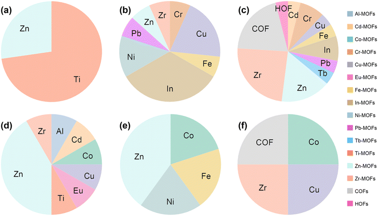 | ||
| Fig. 15 The proportion of MOFs with different metal sites, COFs, and HOFs applied to different functional layers of PSCs. (a) ETL, (b) HTL, (c) PVSK, (d) ETL/PVSK, (e) PVSK/HTL, (f) Elec. and CTL/Elec. The data were analyzed based on Table 1. | ||
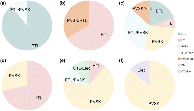 | ||
| Fig. 16 The proportion of typical CPMs applied to different functional layers of PSCs. (a) Ti-MOFs, (b) Ni-MOFs, (c) Zn-MOFs, (d) In-MOFs, (e) Zr-MOFs, (f) COFs and HOFs. The data were analyzed based on Table 1. | ||
Meanwhile, when the perovskite surface was post-processed by Zn-MOFs, water/metal electrodes were prevented from intruding into the perovskite layer. Ti-MOFs (Fig. 15a and 16a) are widely used as an electron transport layer with a small bandgap compared to commercial TiO2, allowing efficient electron transport. In-MOFs (Fig. 15b and 16d) found extensive applications as additives in hole transport layers to accelerate the oxidation of Spiro-OMeTAD. The Ni-MOFs (Fig. 16b) films with controllable thickness were transferred to the ITO substrate as an HTL without doping in an inverted device. Zr-MOFs (Fig. 15c and 16e), COFs, and HOFs (Fig. 15c and 16f) are commonly incorporated into perovskite precursors and self-assembled in situ on perovskite surfaces and grain boundaries, demonstrating a grain ‘caging’ approach.
As shown in Fig. 17, the general relationship between CPMs and measured (non-theoretical) device parameters based on data from almost all CPMs were manually data mined. There is no direct relationship between the relative atomic mass or atomic radius of the metal sites of MOFs and the magnitude of performance enhancement. In one case of Ti-MOFs, the optimized PSCs based on MIL-125@TiO2 composite electron transport material have an efficiency increase of 156% compared to pure TiO2.56 When Zn(II) LH2 was added to the perovskite precursor, the device performance was almost doubled.105 In addition to Zn(II) LH2, other Zn-MOFs also showed significant advantages in enhancing PCE of PSCs, and the percentage of PCE enhancement by 15 cases of Zn-MOFs reached an average of 18.34% with a uniform distribution, Co-MOFs and Pb-MOFs also show great potential for improving PCE. COFs increased PCE by 16.68%, while HOFs were slightly inferior at 10.24%. This may be because the application of HOFs in photovoltaics has just started, and there are too few samples. Notably, benefiting from the flexibility of hydrogen bonds and the rigidity of π–π interactions, HOFs showed potential in releasing residual stress and suppressing metallic Pb leakage, contributing to the preparation of stable and environmentally friendly perovskite solar modules.
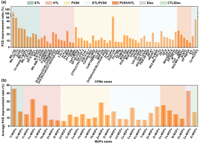 | ||
| Fig. 17 Bar chart of PCEs of (a) all samples and (b) MOFs with different metal sites, COFs, and HOFs applied to different functional layers of PSCs. The data were analyzed based on Table 1. | ||
5. Conclusions and outlook
During the past decade, PSCs have surpassed the highest efficiencies of semiconductor compounds such as CdTe and CIGS and have become a game changer in the PV industry. In addition, t the relatively low preparation cost and more straightforward fabrication process to prepare high-quality perovskite films indicate the great potential of this technology, and it is expected to be an up-and-coming candidate in replacing the dominating silicon solar cells. However, the instability of PSCs under operation-condition includes light, heat, oxygen, moisture, and electrical bias, as well as the environmental aggressiveness of high-efficiency Pb-based light-absorbing perovskite materials, have all been stumbling blocks to the commercialization of PSCs. CPMs are crystalline porous materials with long-range ordered periodic reticular skeletons formed by self-assembling metal/organic or organic/organic molecules. This review focused on the application of CPM materials in various functional layers and interfaces of PSCs to obtain efficient and stable devices.As shown in Fig. 18, CPMs mainly attributed to the following advantages:
(1) With the huge specific surface area and tunable pore size, CPMs have been used as microporous scaffolds to regulate perovskite nucleation or block moisture intrusion, demonstrating their affinity to perovskites as well as their hydrophobic capabilities.
(2) The organic ligands/monomers of CPMs are rich in functional groups, including cyano, carboxyl, carbonyl, and so on, which form a hybrid absorption layer with the perovskite, producing a ‘locked grain boundary’ effect and passivating defects.
(3) Variety CPMs have excellent proton conductivity, and doping in the charge transport layer can improve energy band matching and enhance carrier transportation.
(4) The conjugation of CPM frameworks, most of which can filter UV light, serves as an interface layer between TCO and CTL to reduce damage to the bottom perovskite.
(5) Due to its negatively charged framework, the anionic framework MOFs enhance the absorption of metal atoms/ions and potentially prevent the invasion of calixarenes and the destruction of metal electrodes.
(6) The abundant functional sites around the pores of CPMs have the potential to capture Pb2+ heavy metal ions, which helps to realize stable and environmentally friendly PSCs.
Based on the above analysis, we concluded eight critical points for future research of CPM-based PSCs:
(1) Multifunctional MOFs with the role of porous material-rich functional groups.
Selecting electron-rich metal nodes/organic molecules based on conjugates, functionalizing organic linkers with electron-donating groups, and increasing the conjugation of organic linkers adjust the band gap and semiconductor properties of MOFs. MOFs with optimal energy levels are applied in devices to prepare complete MOF-based PSCs.
(2) Anionic MOFs improve the stability and environment-friendliness of PSCs.
Anionic MOF is self-assembled by the strong electrostatic interaction between the negatively charged skeleton and positive guest counterions (usually amine ions), which not only usually leads to excellent carrier conduction capabilities but also the negatively charged porous framework enhances the absorption of metal atoms/ions, with the potential to inhibit the metal electrodes from destroying the perovskite layer. More importantly, the acid–base pair structure of the anionic framework MOF expands their potential as defects-passivated Lewis acid–base pairs.
(3) Pb-based MOFs as Pb2+ ion sources for perovskite materials.
Pb-based MOF serves as the Pb source of the perovskite layer to reduce the use of metal salts, while the ligand unit serves as a perovskite additive.
(4) CPMs filter ultraviolet light.
Most of the frameworks of CPMs are highly conjugated and thus act as buried interfaces for perovskite to filter UV, reducing damage to the disrupted perovskite layer.
(5) Highly conductive CPMs.
CPMs with ultra-high conductivity promote charge transport and prepare highly conductive and permeable CPM films to replace ITO/FTO on glass or flexible substrates.
(6) CPMs chemisorption of leaked Pb(II) ions in situ.
The use of Pb poses a threat to the environment and human health due to its toxicity, and the substitution of other divalent metals (e.g., tin) for elemental Pb is accompanied by a severe loss of performance. The chemisorption of leaking Pb2+ ions by Pb adsorption materials can fundamentally solve this problem. Considering the porous structure of CPMs and the abundant exposed functional sites in the pores, their ability to prevent Pb2+ ions leakage is expected.
(7) In situ growth of CPMs self-assembled molecular layers as HTLs.
A two-step in situ growth of a self-assembled HTL layer on a TCO substrate expands the choice of hole transport materials. In situ growth methods can achieve conformal coverage on various substrates, promote the development of silicon-based tandem solar cells, simplify the preparation process, optimize device structures, and promote commercial applications.
(8) Robust and flexible HOFs release residual strain.
HOFs have both rigid and flexible properties, which endow the skeleton with strong non-directional deformation ability and act as a ‘rotating joint’ to release the tensile stress during thermal processes through its structural expansion, thus inhibiting ion migration/evaporation and limit the expansion of the perovskite.
Although the application of CPMs in photovoltaics is still in its infancy, existing research has proven the great potential of CPMs. As crystalline porous materials receive more and more attention, it will significantly accelerate the development of this cross-cutting field and promote the commercialization of PSCs.
Author contributions
Conceptualization, C. L. and P. G.; methodology, C. L.; software, C. L.; validation, C. L. and P. G.; formal analysis, C. L.; investigation, C. L.; resources, C. L.; data curation, C. L.; writing—original draft preparation, C. L.; writing—review and editing, P. G.; visualization, P. G.; supervision, P. G.; project administration, P. G.; funding acquisition, P. G. All authors have read and agreed to the published version of the manuscript.Conflicts of interest
The authors declare no conflict of interest.Acknowledgements
P. G. acknowledges the financial support from the National Natural Science Foundation of China (Grant No. 22175180, 21975260).References
- A. Kojima, K. Teshima, Y. Shirai and T. Miyasaka, J. Am. Chem. Soc., 2009, 131, 6050–6051 CrossRef CAS PubMed.
- L. Etgar, P. Gao, Z. Xue, Q. Peng, A. K. Chandiran, B. Liu, Md. K. Nazeeruddin and M. Grätzel, J. Am. Chem. Soc., 2012, 134, 17396–17399 CrossRef CAS PubMed.
- Q. Jiang, Y. Zhao, X. Zhang, X. Yang, Y. Chen, Z. Chu, Q. Ye, X. Li, Z. Yin and J. You, Nat. Photonics, 2019, 13, 460–466 CrossRef CAS.
- Z. Zhang, L. Qiao, K. Meng, R. Long, G. Chen and P. Gao, Chem. Soc. Rev., 2023, 52, 163–195 RSC.
- Best Research-Cell Efficiencies Chart, https://www.nrel.gov/pv/cell-efficiency.html, accessed 5 October.
- Z. Li, C. Wang, P.-P. Sun, Z. Zhang, Q. Zhou, Y. Du, J. Xu, Y. Chen, Q. Xiong, L. Ding, M. K. Nazeeruddin and P. Gao, Nano Energy, 2022, 100, 107468 CrossRef CAS.
- C. Li, N. Zhang and P. Gao, Mater. Chem. Front., 2023, 7, 3797–3802 RSC.
- G. Wenson, H. Tsai, H. Thakkar, J. S. Stein, R. Singh and W. Nie, J. Mater. Chem. A, 2022, 10, 13519–13526 RSC.
- S. Kim, S. Bae, S.-W. Lee, K. Cho, K. D. Lee, H. Kim, S. Park, G. Kwon, S.-W. Ahn, H.-M. Lee, Y. Kang, H.-S. Lee and D. Kim, Sci. Rep., 2017, 7, 1200 CrossRef PubMed.
- J. Li, Q. Dong, N. Li and L. Wang, Adv. Energy Mater., 2017, 7, 1602922 CrossRef.
- X. Cui, J. Jin, J. Zou, Q. Tang, Y. Ai, X. Zhang, Z. Wang, Y. Zhou, Z. Zhu, G. Tang, Q. Cao, S. Liu, X. Liu and Q. Tai, Adv. Funct. Mater., 2022, 32, 2203049 CrossRef CAS.
- S. You, H. Zeng, Z. Ku, X. Wang, Z. Wang, Y. Rong, Y. Zhao, X. Zheng, L. Luo, L. Li, S. Zhang, M. Li, X. Gao and X. Li, Adv. Mater., 2020, 32, 2003990 CrossRef CAS PubMed.
- L. Liang, Q. Xiong, Z. Zhang, Y. Yu and P. Gao, Electrochim. Acta, 2022, 413, 140172 CrossRef CAS.
- H. Tsai, R. Asadpour, J.-C. Blancon, C. C. Stoumpos, O. Durand, J. W. Strzalka, B. Chen, R. Verduzco, P. M. Ajayan, S. Tretiak, J. Even, M. A. Alam, M. G. Kanatzidis, W. Nie and A. D. Mohite, Science, 2018, 360, 67 CrossRef CAS PubMed.
- S. Chen, Y. Deng, X. Xiao, S. Xu, P. N. Rudd and J. Huang, Nat. Sustain., 2021, 4, 636–643 CrossRef.
- H.-S. Kim, Y.-J. An, J. I. Kwak, H. J. Kim, H. S. Jung and N.-G. Park, ACS Energy Lett., 2022, 7, 1154–1177 CrossRef CAS.
- H. Zhang, J.-W. Lee, G. Nasti, R. Handy, A. Abate, M. Grätzel and N.-G. Park, Nature, 2023, 617, 687–695 CrossRef CAS PubMed.
- Q.-Q. Chu, Z. Sun, D. Wang, B. Cheng, H. Wang, C.-P. Wong and B. Fang, Matter, 2023, 6, 3838–3863 CrossRef CAS.
- R. Vidal, J.-A. Alberola-Borràs, S. N. Habisreutinger, J.-L. Gimeno-Molina, D. T. Moore, T. H. Schloemer, I. Mora-Seró, J. J. Berry and J. M. Luther, Nat. Sustain., 2021, 4, 277–285 CrossRef.
- W. Peng, K. Mao, F. Cai, H. Meng, Z. Zhu, T. Li, S. Yuan, Z. Xu, X. Feng, J. Xu, M. D. McGehee and J. Xu, Science, 2023, 379, 683–690 CrossRef CAS PubMed.
- X. Xiao, M. Wang, S. Chen, Y. Zhang, H. Gu, Y. Deng, G. Yang, C. Fei, B. Chen, Y. Lin, D. Dickey Michael and J. Huang, Sci. Adv., 2021, 7, eabi8249 CrossRef CAS PubMed.
- E. Bi, W. Tang, H. Chen, Y. Wang, J. Barbaud, T. Wu, W. Kong, P. Tu, H. Zhu, X. Zeng, J. He, S. Kan, X. Yang, M. Grätzel and L. Han, Joule, 2019, 3, 2748–2760 CrossRef CAS.
- X. Meng, H.-N. Wang, S.-Y. Song and H.-J. Zhang, Chem. Soc. Rev., 2017, 46, 464–480 RSC.
- Y. Ye, L. Gong, S. Xiang, Z. Zhang and B. Chen, Adv. Mater., 2020, 32, 1907090 CrossRef CAS PubMed.
- F. Xiang, S. Chen, S. Zheng, Y. Yang, J. Huang, Q. Lin, L. Wang, S. Xiang and Z. Zhang, ACS Appl. Mater. Interfaces, 2021, 13, 41363–41371 CrossRef CAS PubMed.
- X. Feng, X. Ding and D. Jiang, Chem. Soc. Rev., 2012, 41, 6010–6022 RSC.
- C. S. Diercks and O. M. Yaghi, Science, 2017, 355, eaal1585 CrossRef PubMed.
- B. Wang, R.-B. Lin, Z. Zhang, S. Xiang and B. Chen, J. Am. Chem. Soc., 2020, 142, 14399–14416 CrossRef CAS PubMed.
- R.-B. Lin, Y. He, P. Li, H. Wang, W. Zhou and B. Chen, Chem. Soc. Rev., 2019, 48, 1362–1389 RSC.
- H.-Q. Peng, L.-Y. Niu, Y.-Z. Chen, L.-Z. Wu, C.-H. Tung and Q.-Z. Yang, Chem. Rev., 2015, 115, 7502–7542 CrossRef CAS PubMed.
- Z. Ajoyan, P. Marino and A. J. Howarth, CrystEngComm, 2018, 20, 5899–5912 RSC.
- Y. Chai, X. Han, W. Li, S. Liu, S. Yao, C. Wang, W. Shi, I. da-Silva, P. Manuel, Y. Cheng, L. D. Daemen, A. J. Ramirez-Cuesta, C. C. Tang, L. Jiang, S. Yang, N. Guan and L. Li, Science, 2020, 368, 1002–1006 CrossRef CAS PubMed.
- Y. Yang, L. Li, R.-B. Lin, Y. Ye, Z. Yao, L. Yang, F. Xiang, S. Chen, Z. Zhang, S. Xiang and B. Chen, Nat. Chem., 2021, 13, 933–939 CrossRef CAS PubMed.
- J. Wang, Y. Zhang, P. Zhang, J. Hu, R.-B. Lin, Q. Deng, Z. Zeng, H. Xing, S. Deng and B. Chen, J. Am. Chem. Soc., 2020, 142, 9744–9751 CrossRef CAS PubMed.
- Y. Wang, J. Yan, N. Wen, H. Xiong, S. Cai, Q. He, Y. Hu, D. Peng, Z. Liu and Y. Liu, Biomaterials, 2020, 230, 119619 CrossRef CAS PubMed.
- O. Yildirim, M. Bonomo, N. Barbero, C. Atzori, B. Civalleri, F. Bonino, G. Viscardi and C. Barolo, Energies, 2020, 13, 5602 CrossRef CAS.
- X. Zhou, L. Qiu, R. Fan, J. Zhang, S. Hao and Y. Yang, Nano-Micro Lett., 2020, 12, 2–11 CrossRef PubMed.
- T.-H. Chang, C.-W. Kung, H.-W. Chen, T.-Y. Huang, S.-Y. Kao, H.-C. Lu, M.-H. Lee, K. M. Boopathi, C.-W. Chu and K.-C. Ho, Adv. Mater., 2015, 27, 7229–7235 CrossRef CAS PubMed.
- J. Zhang, S. Guo, M. Zhu, C. Li, J. Chen, L. Liu, S. Xiang and Z. Zhang, Chem. Eng. J., 2021, 408, 127328 CrossRef CAS.
- L. Huang, X. Zhou, R. Wu, C. Shi, R. Xue, J. Zou, C. Xu, J. Zhao and W. Zeng, J. Power Sources, 2019, 433, 226699 CrossRef CAS.
- Y. Liu, T. Liu, X. Guo, M. Hou, Y. Yuan, S. Shi, H. Wang, R. Zhang, C. Galiotis and N. Wang, Adv. Funct. Mater., 2023, 33, 2210028 CrossRef CAS.
- J. Lee, N. Tsvetkov, S. R. Shin and J. K. Kang, ACS Appl. Mater. Interfaces, 2022, 14, 35495–35503 CrossRef CAS PubMed.
- M. Li, D. Xia, A. Jiang, X. Du, X. Fan, L. Qiu, P. Wang, R. Fan and Y. Yang, Energy Technol., 2019, 7, 1900027 CrossRef.
- L. Qiu, K. Xing, J. Zhang, Y. Yang, W. Cao, X. Zhou, K. Zhu, D. Xia and R. Fan, Adv. Funct. Mater., 2021, 31, 2010368 CrossRef CAS.
- Y.-N. Zhang, B. Li, L. Fu, Q. Li and L.-W. Yin, Electrochim. Acta, 2020, 330, 135280 CrossRef CAS.
- H. Yang, J. Zhao, T. Zhou, H. Zhang, W. Zhang, J. Zhang, G. Hu, Y. Zhang and Q. Liu, ACS Appl. Nano Mater., 2023, 6, 16353–16361 CrossRef CAS.
- X. Zhao, J. Zhao, J. He, B. Li, Y. Zhang, J. Hu, H. Wang, D. Zhang and Q. Liu, ACS Appl. Energy Mater., 2020, 3, 6180–6187 CrossRef CAS.
- U. Ryu, S. Jee, J. S. Park, I. K. Han, J. H. Lee, M. Park and K. M. Choi, ACS Nano, 2018, 12, 4968–4975 CrossRef CAS PubMed.
- M.-R. Ahmadian-Yazdi, N. Gholampour and M. Eslamian, ACS Appl. Energy Mater., 2020, 3, 3134–3143 CrossRef CAS.
- C.-K. Liu, K.-H. Wu, Y.-A. Lu, L.-Y. Hsiao, K.-W. Lai, C.-W. Chu and K.-C. Ho, ACS Appl. Mater. Interfaces, 2021, 13, 60125–60134 CrossRef CAS PubMed.
- F. Hazeghi, S. Mozaffari and S. M. B. Ghorashi, J. Solid State Electrochem., 2020, 24, 1427–1438 CrossRef CAS.
- C. Geng, Y. Xie, P. Wei, H. Liu, Y. Qiang and Y. Zhang, Electrochim. Acta, 2020, 358, 136883 CrossRef CAS.
- J. Cao, C.-K. Liu, V. Piradi, H.-L. Loi, T. Wang, H. Cheng, X. Zhu and F. Yan, ACS Energy Lett., 2022, 7, 3362–3369 CrossRef CAS.
- R. Wang, W. Yu, C. Sun, K. Chiranjeevulu, S. Deng, J. Wu, F. Yan, C. Peng, Y. Lou, G. Xu and G. Zou, Nanoscale Res. Lett., 2022, 17, 6 CrossRef CAS PubMed.
- T. M. H. Nguyen and C. W. Bark, ACS Omega, 2020, 5, 2280–2286 CrossRef CAS PubMed.
- A. V. Vinogradov, H. Zaake-Hertling, E. Hey-Hawkins, A. V. Agafonov, G. A. Seisenbaeva, V. G. Kessler and V. V. Vinogradov, Chem. Commun., 2014, 50, 10210–10213 RSC.
- V. A. Gómez Andrade, W. O. Herrera Martínez, F. Redondo, N. B. Correa Guerrero, F. Roncaroli and M. D. Perez, Appl. Mater. Today, 2021, 22, 100915 CrossRef.
- Y. Bai, I. Mora-Seró, F. De Angelis, J. Bisquert and P. Wang, Chem. Rev., 2014, 114, 10095–10130 CrossRef CAS PubMed.
- Z. Zhang, X. Luo, B. Wang and J. Zhang, ACS Appl. Energy Mater., 2019, 2, 2760–2768 CrossRef CAS.
- Y. Dong, J. Zhang, Y. Yang, L. Qiu, D. Xia, K. Lin, J. Wang, X. Fan and R. Fan, Angew. Chem., Int. Ed., 2019, 58, 17610–17615 CrossRef CAS PubMed.
- Y. Dong, J. Zhang, Y. Yang, J. Wang, B. Hu, W. Wang, W. Cao, S. Gai, D. Xia, K. Lin and R. Fan, Nano Energy, 2022, 97, 107184 CrossRef CAS.
- J. Wang, J. Zhang, Y. Yang, S. Gai, Y. Dong, L. Qiu, D. Xia, X. Fan, W. Wang, B. Hu, W. Cao and R. Fan, ACS Appl. Mater. Interfaces, 2021, 13, 5235–5244 CrossRef CAS PubMed.
- J.-Y. Seo, H.-S. Kim, S. Akin, M. Stojanovic, E. Simon, M. Fleischer, A. Hagfeldt, S. M. Zakeeruddin and M. Grätzel, Energy Environ. Sci., 2018, 11, 2985–2992 RSC.
- G. Ren, W. Han, Y. Deng, W. Wu, Z. Li, J. Guo, H. Bao, C. Liu and W. Guo, J. Mater. Chem. A, 2021, 9, 4589–4625 RSC.
- X. Zhou, L. Qiu, R. Fan, H. Ye, C. Tian, S. Hao and Y. Yang, J. Power Sources, 2020, 473, 228556 CrossRef CAS.
- J. Wang, J. Zhang, Y. Yang, Y. Dong, W. Wang, B. Hu, J. Li, W. Cao, K. Lin, D. Xia and R. Fan, Chem. Eng. J., 2022, 429, 132481 CrossRef CAS.
- I. Lee, J. H. Yun, H. J. Son and T.-S. Kim, ACS Appl. Mater. Interfaces, 2017, 9, 7029–7035 CrossRef CAS PubMed.
- L. Caliò, M. Salado, S. Kazim and S. Ahmad, Joule, 2018, 2, 1800–1815 CrossRef.
- J. Wang, J. Zhang, S. Gai, W. Wang, Y. Dong, B. Hu, J. Li, K. Lin, D. Xia, R. Fan and Y. Yang, Adv. Funct. Mater., 2022, 32, 2203898 CrossRef CAS.
- C.-C. Lee, C.-I. Chen, Y.-T. Liao, K. C.-W. Wu and C.-C. Chueh, Adv. Sci., 2019, 6, 1801715 CrossRef PubMed.
- Y. Dong, S. Gai, J. Zhang, R. Fan, B. Hu, W. Wang, W. Cao, J. Wang, K. Zhu, D. Xia, L. Geng and Y. Yang, J. Energy Chem., 2022, 77, 1–10 Search PubMed.
- J. He, H. Liu, F. Zhang, X. Li and S. Wang, Adv. Funct. Mater., 2022, 32, 2110030 CrossRef CAS.
- J. Zhang, J. Duan, Q. Guo, Q. Zhang, Y. Zhao, H. Huang, Y. Duan and Q. Tang, ACS Energy Lett., 2022, 7, 3467–3475 CrossRef CAS.
- J. Zhang, C. Li, M. Zhu, J. Qiu, Y. Yang, L. Li, S. Tang, Z. Li, Z. Mao, Z. Cheng, S. Xiang, X. Zhang and Z. Zhang, Nano Energy, 2023, 108, 108217 CrossRef CAS.
- D. Shen, A. Pang, Y. Li, J. Dou and M. Wei, Chem. Commun., 2018, 54, 1253–1256 RSC.
- W. Sheng, J. He, J. Yang, Q. Cai, S. Xiao, Y. Zhong, L. Tan and Y. Chen, Adv. Mater., 2023, 35, 2301852 CrossRef CAS PubMed.
- Z. Jin, B. Li, Y. Xu, B. Zhu, G. Ding, Y. Wang, J. Yang, Q. Zhang and Y. Rui, J. Mater. Chem. C, 2023, 11, 6730–6740 RSC.
- E. Moshfeghi and M. H. Entezari, Int. J. Energy Res., 2022, 46, 23465–23479 CrossRef CAS.
- Y. Du, H. Cai, Z. Xing, Y. Wu, J. Xu, Z. Li, L. Huang, J. Ni, J. Li and J. Zhang, Org. Electron., 2017, 51, 249–256 CrossRef CAS.
- S. Kuyuldar, D. T. Genna and C. Burda, J. Mater. Chem. A, 2019, 7, 21545–21576 RSC.
- J. Ji, B. Liu, H. Huang, X. Wang, L. Yan, S. Qu, X. Liu, H. Jiang, M. Duan, Y. Li and M. Li, J. Mater. Chem. C, 2021, 9, 7057–7064 RSC.
- J. Dou, C. Zhu, H. Wang, Y. Han, S. Ma, X. Niu, N. Li, C. Shi, Z. Qiu, H. Zhou, Y. Bai and Q. Chen, Adv. Mater., 2021, 33, 2102947 CrossRef CAS PubMed.
- H. Amrollahi Bioki, A. Moshaii and M. Borhani Zarandi, Surf. Interfaces, 2021, 27, 101579 CrossRef CAS.
- M. G. Mohamed, C.-C. Lee, A. F. M. EL-Mahdy, J. Lüder, M.-H. Yu, Z. Li, Z. Zhu, C.-C. Chueh and S.-W. Kuo, J. Mater. Chem. A, 2020, 8, 11448–11459 RSC.
- T. M. Huyen Nguyen and C. W. Bark, J. Alloys Compd., 2020, 841, 155711 CrossRef CAS.
- C. Li, S. Guo, J. Chen, Z. Cheng, M. Zhu, J. Zhang, S. Xiang and Z. Zhang, Nanoscale Adv., 2021, 3, 3554–3562 RSC.
- C. Li, J. Qiu, M. Zhu, Z. Cheng, J. Zhang, S. Xiang, X. Zhang and Z. Zhang, Chem. Eng. J., 2022, 433, 133587 CrossRef CAS.
- X. Yang, Y. Qi, P. Wei, Q. Hu, J. Cheng and Y. Xie, J. Power Sources, 2023, 566, 232927 CrossRef CAS.
- F. Hou, Z. Su, F. Jin, X. Yan, L. Wang, H. Zhao, J. Zhu, B. Chu and W. Li, Nanoscale, 2015, 7, 9427–9432 RSC.
- D. Pourjafari, S. M. P. Meroni, D. Peralta Domínguez, R. Escalante, J. Baker, A. Saadi Monroy, A. Walters, T. Watson and G. Oskam, Energies, 2022, 15, 641 CrossRef CAS.
- Z. Jin, J. Yan, X. Huang, W. Xu, S. Yang, D. Zhu and J. Wang, Nano Energy, 2017, 40, 376–381 CrossRef CAS.
- Y. Li, Q. Chen, T. Xu, Z. Xie, J. Liu, X. Yu, S. Ma, T. Qin and L. Chen, J. Am. Chem. Soc., 2019, 141, 13822–13828 CrossRef CAS PubMed.
- S. Wu, Z. Li, M.-Q. Li, Y. Diao, F. Lin, T. Liu, J. Zhang, P. Tieu, W. Gao, F. Qi, X. Pan, Z. Xu, Z. Zhu and A. K. Y. Jen, Nat. Nanotechnol., 2020, 15, 934–940 CrossRef CAS PubMed.
- P. Wu, S. Wang, X. Li and F. Zhang, Matter, 2022, 5, 1137–1161 CrossRef CAS.
- H. M. Abd El-Lateef, M. M. Khalaf, F. E. Heakal, M. F. Abou Taleb and M. Gouda, Sol. Energy, 2023, 253, 453–461 CrossRef CAS.
- X. Hou, L. Pan, S. Huang, O.-Y. Wei and X. Chen, Electrochim. Acta, 2017, 236, 351–358 CrossRef CAS.
- X. Hou, J. Zhou, S. Huang, W. Ou-Yang, L. Pan and X. Chen, Chem. Eng. J., 2017, 330, 947–955 CrossRef CAS.
- M. Li, J. Wang, A. Jiang, D. Xia, X. Du, Y. Dong, P. Wang, R. Fan and Y. Yang, Sol. Energy, 2019, 188, 380–385 CrossRef CAS.
- M. Li, D. Xia, Y. Yang, X. Du, G. Dong, A. Jiang and R. Fan, Adv. Energy Mater., 2018, 8, 1702052 CrossRef.
- X. Zhou, L. Qiu, R. Fan, A. Wang, H. Ye, C. Tian, S. Hao and Y. Yang, Sol. RRL, 2020, 4, 1900380 CrossRef CAS.
- J. Zhang, L. Hu, W. Cao, Y. Dong, D. Xia, K. Lin and Y. Yang, Inorg. Chem., 2023, 62, 11690–11700 CrossRef CAS PubMed.
- M. A. Islam, V. Selvanathan, P. Chelvanathan, M. Mottakin, M. Aminuzzaman, M. A. Ibrahim, G. Muhammad and M. Akhtaruzzaman, RSC Adv., 2023, 13, 12781–12791 RSC.
- W. Wang, J. Zhang, K. Lin, Y. Dong, J. Wang, B. Hu, J. Li, Z. Shi, Y. Hu, W. Cao, D. Xia, R. Fan and Y. Yang, Adv. Funct. Mater., 2021, 31, 2105884 CrossRef CAS.
- S. Yuan, Y. Xian, Y. Long, A. Cabot, W. Li and J. Fan, Adv. Funct. Mater., 2021, 31, 2106233 CrossRef CAS.
- M. Seifpanah Sowmehesaraee, M. Ranjbar, M. Abedi and S. A. Mozaffari, Sol. Energy, 2021, 214, 138–148 CrossRef CAS.
- X. Liang, K. Zhou, D. Duan, F. Wang, C. Ge, X. Zhou, M. Yuan, Y. Shi, H. Lin, Q. Zhu, G. Li and H. Hu, Chem. Eng. J., 2023, 459, 141524 CrossRef CAS.
- Y. Dong, J. Zhang, W. Wang, B. Hu, D. Xia, K. Lin, L. Geng and Y. Yang, Small, 2023, 19, 2301824 CrossRef CAS PubMed.
- M. S. Sowmehsaraee, M. Abedi and M. Ranjbar, J. Mater. Sci., 2021, 32, 15143–15150 CAS.
- W. Wang, J. Zhang, K. Lin, J. Wang, X. Zhang, B. Hu, Y. Dong, D. Xia and Y. Yang, Adv. Mater., 2023, 35, 2306140 CrossRef CAS PubMed.
- X. Liang, M. Singh, F. Wang, P. W. K. Fong, Z. Ren, X. Zhou, X. Wan, C. M. Sutter-Fella, Y. Shi, H. Lin, Q. Zhu, G. Li and H. Hu, Adv. Sci., 2023, 11, 2305572 CrossRef PubMed.
- Z. Li, Z. Zhang, R. Nie, C. Li, Q. Sun, W. Shi, W. Chu, Y. Long, H. Li and X. Liu, Adv. Funct. Mater., 2022, 32, 2112553 CrossRef CAS.
- C. Wu, Y. Liu, H. Liu, C. Duan, Q. Pan, J. Zhu, F. Hu, X. Ma, T. Jiu, Z. Li and Y. Zhao, J. Am. Chem. Soc., 2018, 140, 10016–10024 CrossRef CAS PubMed.
- B. Li, J. Zhao, Q. Lu, S. Zhou, H. Wei, T. Lv, Y. Zhang, J. Zhang and Q. Liu, Energy Technol., 2021, 9, 2000957 CrossRef CAS.
- H.-Y. Chung, C.-H. Lin, S. Prabu and H.-W. Wang, J. Chin. Chem. Soc., 2018, 65, 1476–1481 CrossRef CAS.
- A. D. Furasova, G. Hix, S. V. Makarov and A. D. Carlo, J. Phys.: Conf. Ser., 2021, 2015, 012042 CrossRef CAS.
- J. Dou, Q. Song, Y. Ma, H. Wang, G. Yuan, X. Wei, X. Niu, S. Ma, X. Yang, J. Dou, S. Liu, H. Zhou, C. Zhu, Y. Chen, Y. Li, Y. Bai and Q. Chen, J. Energy Chem., 2022, 76, 288–294 CrossRef.
- C. Geng, P. Wei, H. Chen, H. Liu, S. Zheng, H. Wang and Y. Xie, Chem. Eng. J., 2021, 414, 128878 CrossRef CAS.
| This journal is © The Royal Society of Chemistry 2024 |


