Enhancement of an electroporation system for gene delivery using electrophoresis with a planar electrode†‡
Keng-Shiang
Huang
a,
Yu-Cheng
Lin
*ab,
Chi-Chang
Su
a and
Chun-Sheng
Fang
a
aDepartment of Engineering Science, National Cheng Kung University, 1 University Road, 701 Tainan, Taiwan, R.O.C. E-mail: yuclin@mail.ncku.edu.tw; Fax: +886-6-276-2329; Tel: +886-6-276-2395
bCenter for Micro/Nano Technology, National Cheng Kung University, 1 University Road, 701 Tainan, Taiwan
First published on 6th October 2006
Abstract
In this paper a new electroporation (EP) system is developed, which includes an EP microchip and a logic circuit, which combined with electrophoresis (ES), can provide site-specific enhancement of gene concentration. In this ES-EP microchip, an arc planar electrode provides the ES function for DNA attraction, and interdigitated array electrodes provide appropriate electric fields for the EP on the chip surface. In addition, the adherent cells can be manipulated in situ without detachment of the ES-EP microchip, which performs the “Lab on a chip”. Experimental results have shown that the efficiency of gene transfection with an attracting-electric field (35.89%) becomes much higher than that without an attracting-electric field (16.62%). Cell numbers as low as 104 cells, and DNA as little as 4 µg are sufficient for evaluating the phenotypic effects following the over-expression of the introduced genes on the ES-EP microchip. The proposed system has the advantages of portability, cost-effectiveness, a high transfection rate and ease of operation.
1. Introduction
Gene therapy is a potential therapeutic modality that requires effective gene delivery into cells and foreign gene expression.1–3 In its simplest terms, a wide range of genes (non-functional in the cells leading to disease development) are introduced into the somatic cell lacking this gene to restore the cell's normal gene function.4 Many gene therapy strategies, however, use genes to destroy specific cells. Such strategies are widely encountered in cancer gene therapy.5Most research on gene therapy has focused on the development of viral-mediated approaches to deliver therapeutic genes to the cells.6–10 However, non-viral-mediated approaches have emerged as a potentially safe and effective gene delivering method for the treatment of a wide variety of acquired and genetic diseases.11–14 Early non-viral gene transfection technologies relied on using self-assemblies of condensing carriers, such as cationic liposomes,15–17 synthetic polymers and peptides,18–20etc. To-date, there are increasing data to support the effectiveness of electroporation (EP) due to the high delivery rates.21–24 EP is a technique that introduces foreign materials into cells by applying impulses with an electric field to create multiple transient pores in the cell membrane through a dielectric breakdown. Moreover, EP can not only be applied to deliver genes in a variety of cell types, but can also be used to deliver protein or even drug into cells.25,26
Generally speaking, a conventional EP device contains a cuvette with a fixed volume for holding samples and two plate electrodes for providing high electric fields, varying from 1 kV cm−1 to 10 kV cm−1.27 Thus, the major challenge for the conventional EP device is that a large portion of cells will be damaged or be lysed by an overly high electric field, that the electrical field is not-uniform in all cells, or that there is an elevated temperature during the EP process.28,29 In order to pursue the more efficient and more stable EP methods to perform gene delivery, several approaches were reported. The main strategies include: (i) physical concentration of DNA at the cell surface,30 (ii) use of magnetic nanoparticles–gene vectors (magnetofection),31 (iii) the controllable circuit32 and others.33–36 However, little attention has been paid to associate these techniques with the EP system.
Recently there has been a surge in the design and fabrication of EP microchips in our lab.37–42 For example, (i) the flow-type EP microchip for suspension cell transfection,37 (ii) the EP microchip with parallel (double) electrodes for adhesion cell transfection,38 (iii) the EP microchip with interdigitated array electrodes for high survival rates using a lower applied voltage (10 V)39 and (iv) the EP microchip with top-and-bottom electrodes for high transfection rates by attracting an electric field (electrophoresis (ES) force).40
Continuing this line of study, and based on utilizing the ES force, we modified the top-and-bottom electrodes of the EP microchip40 to a planar electrode, and in addition we combined this chip with a functional logic circuit for controlling the parameters to make up a new ES-EP system. This ES-EP system has the advantages of: (i) a planar micro-electrode for ease of operation, (ii) the ES force to pre-concentrate DNA and increase the cells' transfection rate, (iii) high density microelectrodes to increase the electric fields, (iv) a low applied voltage to increase the cells' survival rate, (v) a multi-functional logic circuit for simple operation, (vi) integration of the procedures for cell culture, ES, EP and detection on a microchip. This 4-in-1 on-chip operation constitutes the “Lab on a chip” and (vii) the entire procedure is cost-effective and portable.
2. Materials and methods
2.1. Experimental procedure
Prior to culturing the basal cell carcinoma (BCC) cell line in the cell-accommodation cavity of the ES-EP microchip, the microchip was coated with 0.1% gelatin for 6 h. After removal of the gelatin, a total volume of 40 µL of the cells (250 cells µL−1) was seeded onto the pretreated microchip, and was then placed in the incubator and cultured for 24 h. After being cultured for 24 h, the cells on the microchip were washed twice with PBS (phosphate buffered saline). Then 100 µL of 40 µg mL−1 pEGFP-N1 plasmid DNA or 100 µL of 13 nm gold-DNA T21(5′-TTTTTTTTTTTTTTTTTTTTT-SH-3′) conjugate (Au-DNA(T21))43 was added, which was then followed by the ES and EP processes. The cells cultured on the microchip were treated with multiple pulses, and then incubated at 37 °C, 5% CO2 for 24–48 h.2.2. ES and EP processes
Sukharev et al. reported that the first pulse (EP, 6 kV cm−1, 10 µs) efficiently creates pores, but the transfection efficiency is low. However, the second pulse (ES, 0.2 kV cm−1, 10 ms) does not cause poration or transfection by itself, but it enhances transfection efficiency by about one order of magnitude.44 In our study, however, more than 2 EP pulses in sequence would damage the cells. Considering the successful transfection results, these parameters provided a useful reference for further study to find possible optimal transfection conditions. Based on our experience in electroporation,37–41 the optimization conditions were: one ES-pulse for 30 s prior to two-EP-pulses with one pulse duration for 20 ms at 20 ms intervals, and followed by another ES-pulse and two-EP-pulses in reversed polarity (see ESI† Fig. S2c). The first ES process attracted most of the DNA plasmids to the surface of the cell membrane, and it was then followed by the EP process. The second ES pulse attracted the remainder of the negatively-charged DNA plasmids, which were not delivered to the cells with the first EP pulses, to the surface of the cell membrane for the second EP process.40,41In the ES process, a 3 V pulse of 30 s duration was applied to the interdigitated electrodes and with a grounded arc electrode. In the EP process, two pulses of 6 V of 20 ms were applied to one interdigitated electrode while the other interdigitated electrode was grounded. At the same time, the arc electrode was in an open circuit situation. After the first two-EP-pulse, the second EP process proceeded with the same duration, except with reversed polarity. The electric waveform under the ES and EP processes by the logic circuit is available in the ESI† (see ESI Fig. S2c).
3. Results and discussion
3.1. Design of planar electrode for ES
Recently we have been using the top and bottom electrode designs for ES.40 However, there are several major deficiencies with such a device. For example, (i) PDMS (polydimethyl siloxane) is a rather soft material, with the result that the distance between the top and bottom electrodes is difficult to maintain, influencing the electric field between the two electrodes, leading to unstable transfection rates. (ii) The EP device is inconvenient to operate due to the fact that it uses top and bottom electrodes, which is a non-modular design, necessitating extra sterilization procedures of the cell culture. (iii) The liquid sample and buffer in the cavity can leak from the top electrodes, which leads to inaccuracy and contamination. And (iv) the generation of bubbles, a hard-to-eliminate byproduct during the ES process, influences the contact between the top electrodes and the surface of the buffer. Because of these drawbacks, a brand-new experimental apparatus with planar electrode for ES was designed.Fig. 1(a) illustrates the DNA attraction and targeting mechanism by the ES force with planar electrode on the ES-EP microchip. A certain amount of DNA plasmids are added into the well of the microchip prior to the EP process. As the anode is connected to one side of the interdigitated electrodes (ES process), the DNA plasmids are attracted and accumulated at the finger electrodes with positive polarity, which increases the DNA concentration on the surface of the powered electrodes or the cells. After the DNA plasmids are accumulated, the electric power is switched to the interdigitated electrodes to perform the cell EP process, as shown in Fig. 1(b). DNA plasmids are then delivered into the cells.
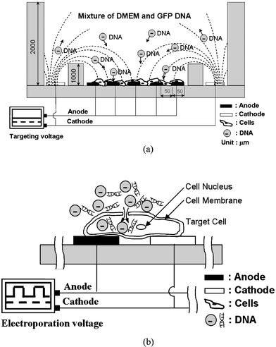 | ||
| Fig. 1 Illustrations of the experimental principle and mechanism on the ES-EP microchip. (a) Negatively-charged DNA plasmids are driven from the negative polarity electrode to the positive polarity electrodes by the ES force on the ES-EP microchip. (b) After the ES function, the negatively-charged DNA plasmids are accumulated at the cell surfaces, and are then delivered into the cells by applying impulses with an electric field (EP). | ||
3.2. Simulated electric field distributions (ES force) of the ES-EP microchip
A computer simulation was performed to investigate the magnitude and distribution of the electric field under DNA attracting conditions in the cell-accommodation cavity of an ES-EP microchip, to assist with the chip design. Simulations were performed using the CFD-ACE™ (CFD Research Corporation, Alabama, USA). The 3D structure of the simulation is an asymmetric model. The simulation was implemented in the steady state. The electric field under the applied voltage was solved with the boundary conditions of the fixed voltages at the arc of the ES electrode and interdigitated electrodes. In the 3D simulated structure, the electric properties of water are substituted for that of DNA buffer, and the boundaries of the structure are insulated. The material of the ES electrode and the EP electrodes is gold. The power law method was applied to achieve higher density grids and obtain better resolutions. The number of calculated nodes and elements were 226![[thin space (1/6-em)]](https://www.rsc.org/images/entities/char_2009.gif) 164 and 972
164 and 972![[thin space (1/6-em)]](https://www.rsc.org/images/entities/char_2009.gif) 758, respectively. In order to attract the DNA plasmids to specific areas by using the electrostatic force, the electric field is generated by grounding the ES electrode, i.e. the cathode electrode, and applying 3 V to one finger electrode of the interdigitated electrodes. Based upon the volume of the medium, electrode dimension and interval, the typical electric field variation of the ES-EP chip are plotted, as shown in Fig. 2(a).
758, respectively. In order to attract the DNA plasmids to specific areas by using the electrostatic force, the electric field is generated by grounding the ES electrode, i.e. the cathode electrode, and applying 3 V to one finger electrode of the interdigitated electrodes. Based upon the volume of the medium, electrode dimension and interval, the typical electric field variation of the ES-EP chip are plotted, as shown in Fig. 2(a).
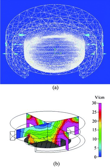 | ||
| Fig. 2 Simulated electric field distributions of the ES-EP microchip under a specific electrode targeting process. (a) Close-up view of a discretization model. (b) A cross-sectional view of the electric field distribution in the vicinity of the interdigitated electrodes and the ES electrode. | ||
Fig. 2(b) shows the cross-sectional view of the electric field distribution in the media using the planar arc electrode. Generally speaking, DNA plasmids are negatively-charged. The arc electrode is of lower electric potential with respect to that of the interdigitated electrodes. Therefore, the negatively-charged DNA plasmids are spontaneously driven from the negative polarity (arc) electrode to the positive polarity (interdigitated) electrodes by the ES force. Based on Fig. 2(b), we proposed that as time progresses the DNA plasmids migrate from everywhere to the interdigitated electrodes. Thus, the high electric field strength will attract most of the DNA plasmids to the interdigitated electrodes, thereby further increasing the DNA concentration at the anode, and facilitating gene delivery.
In addition, we picked four points on the electrode bottom to make advanced observations of the electric field change. The electric field distributions at these four points at the Z axis of the ES-EP chip are plotted in Fig. 3. The electric fields near the surface of the four coordinates are around 20 V cm−1 with a variation of 15% (Fig. 4(b)–4(e)). In addition, we used 50 µm, 100 µm, and 200 µm electrode gap interdigitated electrodes to undergo the same simulation, and similar electric field distributions were observed. Therefore, we conclude that the gap of the interdigitated electrodes is not a key parameter to the ES situation in this proposed device.
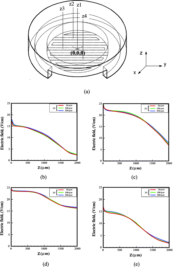 | ||
| Fig. 3 Local electric field distributions: (a) the cell-accommodation cavity (working area) is partitioned into four coordinates, z1 to z4. The electric field change of position (b) z1 (0, 0, 0), (c) z2 (0, 1, 0), (d) z3 (−1, 0, 0), and (e) z4 (0, −1, 0). | ||
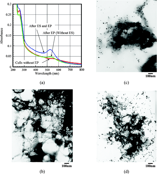 | ||
| Fig. 4 Comparison of the delivery efficiency of Au-DNA(T21) conjugates in a BCC cell line with/without performing the ES process of EP. The images of (a) the UV-Vis spectrum, (b) the TEM photo of the smashed BCC cells, (c) the TEM photo of BCC cells under the conditions of the EP process (without the ES process), and (d) the TEM photo of BCC cells under the conditions of the ES and the EP processes. (The black spots in (b), (c) and (d) indicate the Au-DNA(T21) conjugates. The clouds are the pulverized shape of the BCC cells.) | ||
Since changing the gap between the fingers influences the electric field between the fingers itself, the field distribution and strength will be different for the different electrode gaps, and further influence the EP results. Based on our previous studies,40 we chose the 50 µm electrode gap design of the interdigitated electrodes for the experiments. When the gap size between two finger electrodes is narrow, the distribution of the electric field strength in the EP process will be more uniform to the covered cells. Also, a narrow gap increases the adhesion ratio of cells on the interdigitated electrodes; resulting in a substantially improved delivery efficiency of EP (the electroporated cells were mostly located on the interdigitated electrodes).
3.3. Evaluation of the ES-EP microchip by pEGFP-N1 plasmids
We mainly use a fluorescence microscope to observe the experiment results, and a transmission electron microscope (TEM) to make the advanced observations. Generally speaking, the successfully transfected cells with the pEGFP-N1 plasmid exhibit green fluorescence, which is used to compare the qualitative transfection efficiencies with or without the performing targeting process (i.e. ES) of EP.Fig. 5 shows the experiment results of the pEGFP-N1 plasmids transfection with/without ES process of EP in the BCC cells. We find that most of the transfected BCC cells are located on the anodic electrodes. Moreover, without applying an attracting-electric field process (i.e. ES process) in the EP, the BCC cells show a random distribution, and less transfection of the pEGFP-N1 plasmids (Fig. 5(c)). When an ES process is used in the EP, the transfection efficiency can be enhanced and the transfected cells can be targeted in specific regions (on the anodic electrodes), as shown in Fig. 5(d). The experimental data show that the pEGFP-N1 plasmids (green spots) are successfully transfected into the BCC cells, and that the ES process can aid in improving the EP system and elevate the transfection rate from 16.62% to 35.89%. It is evident that substantially more transfected cells were found with the EP procedure using a targeting field (i.e. ES process) than without applying a target field. On the other hand, if we just use the ES force (3 V, 30 s) in a two-pulse mode only, then nearly no transfection is observed in our experiments.
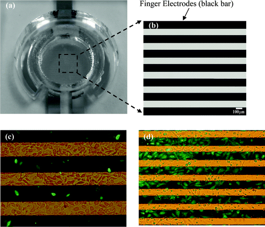 | ||
| Fig. 5 Comparing the pEGFP-N1 plasmid transfection efficiency of basal cell carcinoma cell line (BCC) with/without the ES force in the EP process. (a) An image of the observation area. (b) A magnified view of the observation area. Photos of (c) BCC cells without the ES procedure (after EP), (d) BCC cells with the ES procedure (after EP). Green fluorescence spots mean the successful transfection of pEGFP-N1 plasmids in the cells. The black rectangles are the interdigitated electrodes. | ||
3.4. Evaluation of the ES-EP microchip using Au-DNA(T21) conjugates
In order to test the applicability of the proposed ES-EP microchip, the Au-DNA(T21) conjugates were studied as well. The gold nanoparticles can be used as an ideal label for DNA, and only a small sample volume is needed. The 13 nm gold nanoparticles have an absorption peak around 520 nm in UV-Vis spectroscopy. Also, the Au-DNA(T21) conjugates have a similar absorption peak around 520 nm. The delivery efficiency of Au-DNA(T21) conjugates can be easily differentiated by examining the shift in the UV-Vis spectrum and the TEM image, as shown in Fig. 4. Before undergoing the EP process, nearly no absorption peaks were observed around 520 nm. However, after undergoing the EP process, a broad peak was observed. The intensity of the absorption of the UV-Vis obtained from the EP process only is obviously lower than that of the EP with the ES process (Fig. 4(a)). Apparently, the attracting-electric fields (ES force) can enhance the delivery efficiency. In addition, TEM is used to make advanced observations (Fig. 4(b)–(d)). It is presumed that the delivery efficiency can be evaluated by observing the black spots (Au-DNA(T21) conjugates). Experimental data show that if the EP process is combined with the ES function, the delivery efficiency can be enhanced (Fig. 4(c)vs. 4(d)).4. Conclusions
Targeting and enhancing in vitro gene delivery using electrophoresis with a planar electrode is not available in commercial equipment. Our ES-EP system for controlling gene location and transfection is efficient and unique. It turns out to be one of the more efficient methods for gene delivery. Based on the simulation results we anticipate that a high electric field strength can attract most of the DNA plasmids to the powered electrode fingers, thereby further increasing the DNA concentration at the anode, and so facilitating the gene delivery. The experimental results of the ES process can aid in the improvement of the EP system and in elevating the pEGFP-N1 transfection rate from 16.62% to 35.89%. Compared with conventional EP equipment our proposed ES-EP microchip has the advantages of requiring less cells and plasmids, lower electroporation voltages, and simpler cell culturing and preparation processes. These advantages make the applications of the ES-EP microchip to various cell lines essentially inexhaustible.Acknowledgements
Funding from the Ministry of Education and the National Science Council of Taiwan, R.O.C. under contract no. (NSC 94-2323-B-006-005, NSC 94-2323-B-006-006) is gratefully acknowledged.References
- I. M. Verma and N. Somia, Gene therapy - promises, problems and prospects, Nature, 1997, 389, 239–242 CrossRef CAS.
- M. Cavazzana-Calvo, A. Thrasher and F. Mavilio, The future of gene therapy, Nature, 2004, 427, 779–781 CrossRef CAS.
- A. D. Miller, Human gene therapy comes of age, Nature, 1992, 357, 455–460 CrossRef CAS.
- C. Fillat, M. Carrio, A. Cascante and B. Sangro, Suicide gene therapy mediated by the herpes simplex virus thymidine kinase gene/ganciclovir system: fifteen years of application, Curr. Gene Therapy, 2003, 3, 13–26 Search PubMed.
- J. Clayton, Gene therapy progress for HIV, Drug Discovery Today, 2002, 7, 841–842 CrossRef.
- E. Check, Gene therapy: a tragic setback, Nature, 2002, 420, 116–118 CrossRef CAS.
- G. R. Sambrano, I. Fraser, H. Han, Y. Ni, T. O'Connell, Z. Yan and J. T. Stull, Navigating the signalling network in mouse cardiac myocytes, Nature, 2002, 420, 712–714 CrossRef CAS.
- M. Izquierdo, Short interfering RNAs as a tool for cancer gene therapy, Cancer Gene Therapy, 2005, 12, 217–227 Search PubMed.
- E. Tasciotti, M. Zoppè and M. Giacca, Transcellular transfer of active HSV-1 thymidine kinase mediated by an 11-amino-acid peptide from HIV-1 Tat, Cancer Gene Therapy, 2003, 10, 64–74 Search PubMed.
- C.-F. Lee, S.-Y. Chang, D.-S. Hsieh and D.-S. Yu, Treatment of bladder carcinomas using recombinant BCG DNA vaccines and electroporative gene immunotherapy, Cancer Gene Therapy, 2004, 11, 194–207 Search PubMed.
- E. Tomlinson and A. P. Rolland, Controllable gene therapy pharmaceutics of non-viral gene delivery systems, J. Controlled Release, 1996, 39, 357–372 CrossRef CAS.
- I. A. Pringle, S. Raman, W. W. Sharp, S. H. Cheng, S. C. Hyde and D. R. Gill, Detection of plasmid DNA vectors following gene transfer to the murine airways, Gene Therapy, 2005, 12, 1206–1214 Search PubMed.
- C. Murphy, R. Saffrich, M. Grummt, H. Gournier, V. Rybin, M. Rubino, P. Auvinen, A. Lütcke, R. G. Parton and M. Zerial, Endosome dynamics regulated by a Rho protein, Nature, 1996, 384, 427–432 CrossRef CAS.
- A. C. Rose, C. A. Goddard, W. H. Colledge, S. H. Cheng, D. R. Gill and S. C. Hyde, Optimisation of real-time quantitative RT-PCR for the evaluation of non-viral mediated gene transfer to the airways, Gene Therapy, 2002, 9, 1312–1320 Search PubMed.
- N.-S. Yang and W. H. Sun, Gene gun and other non-viral approaches for cancer gene therapy, Nat. Med., 1995, 1, 481–483 CrossRef CAS.
- P. L. Felgner and G. M. Ringold, Cationic liposome-mediated transfection, Nature, 1989, 337, 387–388 CrossRef.
- Y. Liu, L. C. Mounkes, H. D. Liggitt, C. S. Brown, I. Solodin, T. D. Heath and R. J. Debs, Factors influencing the efficiency of cationic liposome-mediated intravenous gene delivery, Nat. Biotechnol., 1997, 15, 167–173 CrossRef CAS.
- J. Haensler and F. C. Szoka, Polyamidoamine cascade polymers mediate efficient transfection of cells in culture, Bioconjugate Chem., 1993, 4, 372–379 CrossRef CAS.
- S. Simões, V. Slepushkin, P. Pires, R. Gaspar, M. C. P. de Lima and N. Düzgüne, Mechanisms of gene transfer mediated by lipoplexes associated with targeting ligands or pH-sensitive peptides, Gene Therapy, 1999, 6, 1798–1807 Search PubMed.
- O. J. Müller, F. Kaul, M. D. Weitzman, R. Pasqualini, W. Arap, J. A. Kleinschmidt and M. Trepel, Random peptide libraries displayed on adeno-associated virus to select for targeted gene therapy vectors, Nat. Biotechnol., 2003, 21, 1040–1046 CrossRef.
- A. Peister, J. A. Mellad, M. Wang, H. A. Tucker and D. J. Prockop, Stable transfection of MSCs by electroporation, Gene Therapy, 2004, 11, 224–228 Search PubMed.
- D. J. Wells, Gene therapy progress and prospects: electroporation and other physical methods, Gene Therapy, 2004, 11, 1363–1369 Search PubMed.
- C.-M. Wu, M.-W. Lin, J.-T. Cheng, Y.-M. Wang, Y.-W. Huang, W.-Z. Sun and C.-R. Lin, Regulated, electroporation-mediated delivery of pro-opiomelanocortin gene suppresses chronic constriction injury-induced neuropathic pain in rats, Gene Therapy, 2004, 11, 933–940 Search PubMed.
- R. Heller, The development of electroporation, Science, 2002, 295, 277 CAS.
- F. André and L. M. Mir, DNA electrotransfer: its principles and an updated review of its therapeutic applications, Gene Therapy, 2004, 11, S33–S42 Search PubMed.
- T. Nishi, K. Yoshizato, S. Yamashiro, H. Takeshima, K. Sato, K. Hamada, I. Kitamura, T. Yoshimura, H. Saya, J. Kuratsu and Y. Ushio, High-efficiency in vivo gene transfer using intraarterial plasmid DNA injection following in vivo electroporation, Cancer Res., 1996, 56, 1050–1055 CAS.
- E. Neumann, M. Schaefer-Ridder, Y. Wang and P. H. Hofschneider, Gene transfer into mouse lyoma cells by electroporation in high electric fields, EMBO J., 1982, 1, 841–845 CAS.
- S. J. Beebe, P. M. Fox, L. J. Rec, L. K. Willis and K. H. Schoenbach, Nanosecond, high-intensity pulsed electric fields induce apoptosis in human cells, FASEB J., 2003, 17, 1493–1495 CAS.
- J. A. White, P. F. Blackmore, K. H. Schoenbach and S. J. Beebe, Stimulation of capacitative calcium entry in HL-60 cells by nanosecond pulsed electric fields, J. Biol. Chem., 2004, 279, 22964–22972 CrossRef CAS.
- D. Luo and W. M. Saltzman, Enhancement of transfection by physical concentration of DNA at the cell surface, Nat. Biotechnol., 2000, 18, 893–895 CrossRef CAS.
- F. Scherer, M. Anton, U. Schillinger, J. Henke, C. Bergemann, A. Krüger, B. Gänsbacher and C. Plank, Magnetofection: enhancing and targeting gene delivery by magnetic force in vitro and in vivo, Gene Therapy, 2002, 9, 102–109 Search PubMed.
- Y. Huang and B. Rubinsky, Microfabricated electroporation chip for single cell membrane permeabilization, Sens. Actuators, A, 2001, 89, 242–249 CrossRef.
- F. Nicol, M. Wong, F. C. MacLaughlin, J. Perrard, E. Wilson, J. L. Nordstrom and L. C. Smith, Poly-L-glutamate, an anionic polymer, enhances transgene expression for plasmids delivered by intramuscular injection with in vivo electroporation, Gene Therapy, 2002, 9, 1351–1358 Search PubMed.
- M. Sakai, M. Nishikawa, O. Thanaketpaisarn, F. Yamashita and M. Hashida, Hepatocyte-targeted gene transfer by combination of vascularly delivered plasmid DNA and in vivo electroporation, Gene Therapy, 2005, 12, 607–616 Search PubMed.
- M. H. Wu, S. L. Smith, G. H. Danet, A. M. Lin, S. F. Williams, D. N. Liebowitz and M. E. Dolan, Optimization of culture conditions to enhance transfection of human CD34+ cells by electroporation, Bone Marrow Transplant., 2001, 27, 1201–1209 CrossRef CAS.
- D. C. Chang, P. Q. Gao and B. L. Maxwell, High efficiency gene transfection by electroporation using a radio-frequency electric field, Biochim. Biophys. Acta, 1991, 1092, 153–160 CAS.
- Y. C. Lin, C. M. Jen, M. Y. Huang and X. Z. Lin, Electroporation microchips for continuous gene transfection, Sens. Actuators, B, 2001, 79, 137–143 CrossRef.
- Y. C. Lin and M. Y. Huang, Electroporation microchips for in vitro gene transfection, J. Micromech. Microeng., 2001, 11, 542–547 CrossRef CAS.
- Y. C. Lin, M. Li, C. S. Fan and L. W. Wu, A microchip for electroporation of primary endothelial cells, Sens. Actuators, A, 2003, 108, 12–19 CrossRef.
- Y. C. Lin, M. Li and C. C. Wu, Simulation and experimental demonstration of the electric field assisted electroporation microchip for in vitro gene delivery enhancement, Lab Chip, 2004, 4, 104–108 RSC.
- C. P. Jen, W. M. Wu, M. Li and Y. C. Lin, Site-specific enhancement of gene transfection utilizing an attracting electric field for DNA plasmids on the electroporation microchip, J. Micromech. Microeng., 2004, 13, 947–955 CAS.
- Y. C. Lin, H. C. Ho, C. K. Tseng and S. Q. Hou, A poly-methylmethacrylate electrophoresis microchip with sample preconcentrator, J. Micromech. Microeng., 2001, 11, 189–194 CrossRef CAS.
- J. J. Storhoff, R. Elghanian, C. A. Mirkin and R. L. Letsinger, Sequence-dependent stability of DNA-modified gold nanoparticles, Langmuir, 2002, 18, 6666–6670 CrossRef CAS.
- S. I. Sukharev, V. A. Klenchin, S. M. Serov, L. V. Chernomordik and Y. A. Chizmadzhev, Electroporation and electrophoretic DNA transfer into cells. The effect of DNA interaction with electropores, Biophys. J., 1992, 63, 1320–1327 CrossRef CAS.
Footnotes |
| † Electronic supplementary information (ESI) available: Fabrication of an ES-EP microchip, design of a logic circuit for the ES-EP system, plasmids preparation, cell culture maintenance and detection system. See DOI: 10.1039/b613753a |
| ‡ The HTML version of this article has been enhanced with additional colour images. |
| This journal is © The Royal Society of Chemistry 2007 |
