DOI:
10.1039/B811217G
(Review Article)
Energy Environ. Sci., 2009,
2, 55-67
Hydrogel-polymer electrolytes for electrochemical capacitors: an overview
Received
1st July 2008
, Accepted 24th October 2008
First published on 1st December 2008
Abstract
Electrochemical capacitors are electrochemical devices with fast and highly reversible charge-storage and discharge capabilities. The devices are attractive for energy storage particularly in applications involving high-power requirements. Electrochemical capacitors employ two electrodes and an aqueous or a non-aqueous electrolyte, either in liquid or solid form; the latter provides the advantages of compactness, reliability, freedom from leakage of any liquid component and a large operating potential-window. One of the classes of solid electrolytes used in capacitors is polymer-based and they generally consist of dry solid-polymer electrolytes or gel-polymer electrolyte or composite-polymer electrolytes. Dry solid-polymer electrolytes suffer from poor ionic-conductivity values, between 10−8 and 10−7 S cm−1 under ambient conditions, but are safer than gel-polymer electrolytes that exhibit high conductivity of ca. 10−3 S cm−1 under ambient conditions. The aforesaid polymer-based electrolytes have the advantages of a wide potential window of ca. 4 V and hence can provide high energy-density. Gel-polymer electrolytes are generally prepared using organic solvents that are environmentally malignant. Hence, replacement of organic solvents with water in gel-polymer electrolytes is desirable which also minimizes the device cost substantially. The water containing gel-polymer electrolytes, called hydrogel-polymer electrolytes, are, however, limited by a low operating potential-window of only about 1.23 V. This article reviews salient features of electrochemical capacitors employing hydrogel-polymer electrolytes.

N. A. Choudhury | N. A. Choudhury is currently a Research Scholar at the Solid State and Structural Chemistry Unit, Indian Institute of Science, Bangalore. His research interests are in materials electrochemistry with emphasis on electrolytes for fuel cells, supercapacitors and batteries. |
 S. Sampath | S. Sampath is an Associate Professor at the Inorganic and Physical Chemistry Department, Indian Institute of Science, Bangalore. His recent research interests are in interfacial electrochemistry including organic thin-films, exfoliated graphite, nanoparticles and transition-metal nitrides and carbides. |
 A. K. Shukla | A. K. Shukla is a Professor at the Solid State and Structural Chemistry Unit, Indian Institute of Science, Bangalore. His recent research interests are in materials electrochemistry with emphasis on fuel cells, batteries, supercapacitors and solid ionics. He is also the Director of the Central Electrochemical Research Institute, Karaikudi, India. |
Broader context
Electrochemical capacitors (ECs) are electrochemical energy storage devices with high power densities. ECs possess properties that are complementary to secondary batteries and hence can be hybridized to yield devices, which can be employed as power sources for high power applications such as electric vehicles, utility load-leveling, heavy-load starting assists for diesel locomotives, military and medical applications as also for low-power applications such as camera-flash equipment, lasers and as back-up power for computer memory. Electrochemical capacitors employ two electrodes and an aqueous or a non-aqueous electrolyte, either in liquid or solid form. Solid electrolytes provide certain advantages such as freedom from leakage of any liquid component, compactness and reliability. Solid electrolytes employed in ECs are mostly polymer-based and are classified as solid-polymer electrolytes, gel-polymer electrolytes and composite-polymer electrolytes. Solid-polymer electrolytes exhibit lower ionic conductivity values than gel-polymer electrolytes. Gel-polymer electrolytes are generally prepared using organic solvents that are environmentally malignant. Hence, replacement of organic solvents with water in gel-polymer electrolytes is desirable, which also minimizes the device cost substantially. The water containing gel-polymer electrolytes are called hydrogel-polymer electrolytes.
|
1. Introduction
Electrochemical capacitors (ECs) are energy storage devices with high power densities as evident from the Ragone plot shown in Fig. 1. ECs are complementary to secondary batteries and are projected as future power sources for high-power applications such as electric vehicles, utility load-leveling, heavy-load starting assists for diesel locomotives, military and medical applications as also low-power applications such as camera-flash equipment, lasers, pulsed-light generators, and as back-up power for computer memory.1–3 On the basis of mechanisms involved in the charge-storage process, an EC is classified as an electrical double-layer capacitor (EDLC) or a pseudocapacitor. An EDLC typically comprises an electrolyte sandwiched between two electrodes. High energy-density of EDLCs, as compared to dielectric capacitors, arises due to the large surface-area of the electrode materials such as activated carbons,4–6 aerogel or xerogel carbons,4,5,7–9carbon nanotubes,4,5,10,11 and exfoliated graphite.12 Owing to the physical nature of charge storage and discharge, EDLCs have several advantages over secondary batteries, viz. faster charge–discharge, longer cycle-life (>105 cycles), and higher power-density.1 Pseudocapacitors, also referred to as redox capacitors, involve redox reactions in the charge storage and delivery processes. Energy-storage mechanisms in pseudocapacitors involve fast Faradaic reactions such as intercalation, underpotential deposition or redox processes occurring at or near a solid–electrode surface at an appropriate potential.1Redox processes often occur in metal oxides,1,4,13–22 conducting polymers1,4,23–25 and hybrid organic–inorganic nanocomposite materials26 making them attractive electrode materials for pseudocapacitors.
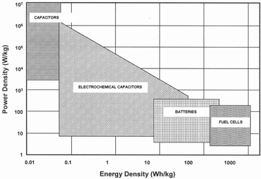 |
| | Fig. 1 A Ragone plot comparison of power and energy densities for electrochemical capacitors, storage batteries and fuel cells. | |
The ECs employ either aqueous or non-aqueous electrolytes and it may be in liquid or solid form, the latter providing advantages of compactness, reliability, freedom from leakage of any liquid component and a large operating potential-window. The vapour pressure of the solid electrolytes is generally low and hence they are amenable for use at higher than ambient temperatures. They are also relatively easy to handle. Polymeric solid electrolytes are flexible, and can be easily fabricated as thin and large area membranes facilitating low internal-resistance. They also enhance the operational reliability of the ECs. Polymer electrolytes are the most widely studied solid electrolytes.27–29 Complexation of functional-groups of certain polymers with cations results in the formation of polymer–cation complexes commonly referred to as solid-polymer electrolytes (SPEs).28 Fenton et al.30 and Wright31 were the first to report the ionic conductivity measurements on poly(ethylene oxide) (PEO)–alkali metal salt complexes. However, it was Armand et al., in 1978,32 who pointed out the potential use of these materials in batteries. In order to achieve a well-complexed polymer–metal salt system, the choice of polymer as well as the metal salt is of utmost importance. The choice of a host polymer depends principally on factors such as (i) presence of a sequential functional group with high electron donation capability to form a strong coordinate bond with a metal ion, (ii) a low steric hindrance to bond rotations so that the polymer chain mobilities called segmental motions is facilitated, and (iii) an appropriate distance between the donor atom and the cation.33 The complexation of cations with the functional groups of the polymer and the stability of the resulting polymer–cation complex are explained on the basis of the Hard–Soft Acid–Base (HSAB) principle. Based on the HSAB principle, the polymers are considered as arrays of hard or soft bases that form coordination bonds with cations. The stability of polymer electrolytes is primarily dictated by the polymer–cation solvation energy with only a little contribution from the lattice energy of the salt.28
Ionic mobility in SPEs has been reported to be due to segmental motion and the ion transport is mainly restricted to the amorphous phase of the polymer electrolytes.34Mixing a polymer with an alkali metal salt dissolved in an organic solvent results in the formation of a gel-polymer electrolyte (GPE).35 GPEs exhibit liquid-like ionic conductivity while maintaining the dimensional stability of a solid system. Various polymers, such as poly(propylene oxide), poly(ethylene imine), thio-alkane, polystyrene, poly(vinyl alcohol),28 poly(vinylidene fluoride) (PVdf),36 poly(vinylidene carbonate), poly(acrylonitrile),37,38 poly(vinyl chloride),39 poly(vinyl sulfone),40 poly(p-phenylene tereththalamide),41 and poly(vinylpyrolidone), have been reported to form GPEs with conductivities ranging between 10−4 and 10−3 S cm−1 under ambient conditions.39 The low molecular-weight organic solvents with high dielectric constants employed in GPEs are commonly referred to as plasticizers. Solvents such as ethylene carbonate, propylene carbonate, tetrahydrofuran,42dimethyl formamide, diethyl carbonate, diethyl phthalate, methylethyl carbonate, γ-butyrolactone, dimethylcarbonate, glycol sulfite, and alkyl phthalates, have been commonly employed as ‘plasticizers’ in GPEs.43,44 The glass-transition temperature of GPEs varies with the extent of plasticization which depends on the proportion of polymer and plasticizer in the GPEs. GPEs are generally prepared by heating a mixture of appropriate quantities of a polymer, a plasticizer and a salt to a temperature above the glass-transition temperature of the polymer followed by casting the resultant hot viscous solution onto a glass plate and cooling to ambient temperatures. When water is used as a plasticizer, the gelled polymer electrolyte is referred to as ‘hydrogel-polymer electrolyte’.
Hydrogels are three-dimensional polymeric networks that trap water in the polymer matrices mainly by surface tension. Based on the nature of the pendant groups in the precursor, hydrogels are classified as neutral or ionic, while the classification as affine or phantom networks is based on their structural and mechanical features. Alternatively, depending on the nature of the polymer, hydrogels are classified as homopolymeric or copolymeric hydrogels. Hydrogels are further classified as amorphous, semi-crystalline, hydrogen-bonded structures, supramolecular structures and hydrocolloidal aggregates based on the physical structure of the network.45 The three-dimensional network formation of hydrogels and their insolubility in the precursor solution are due to the presence of chemical cross-linkages or physical entanglements. Physical hydrogels differ from chemical hydrogels in the type of cross-linkages, randomness of the network formation, and the effects of these parameters on the rigidity and elastic moduli of the resultant networks. Unlike the covalent cross-linking points in chemical hydrogels formed by the reaction between the polymer and a cross-linking reagent such as glutaraldehyde, physical hydrogels are formed through association of several laterally associated polymer helices in extended junction zones, wherein the hydrogel network is stabilized by physical entanglements, electrostatic attractive forces and hydrogen bonding. The schematic diagram of a chemical hydrogel with point cross-links and a physical hydrogel with multiple junction zones are shown in Fig. 2(a) and (b), respectively. Physical hydrogels are thermally reversible and can be viewed as viscoelastic solids.46 Physiologically responsive hydrogels often show a swelling behavior in response to a changing external environment. Some of the factors responsible for the swelling behavior are pH, ionic strength, temperature and electromagnetic radiation.
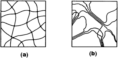 |
| | Fig. 2 Schematic diagram of (a) a chemical hydrogel with point cross-links and (b) a physical hydrogel with multiple-junction zones. In (a) the solid lines represent polymer chains that constitute the hydrogel matrix. The solid dots in the cross-link points of the polymer helices represent the cross-links formed by chemical reaction between the polymer such as PVA and a cross-linking reagent such as gluteraldehyde. In (b) the solid lines represent the polymer helices aligning themselves laterally in extended junction zones (from ref. 46). | |
Poly(vinyl alcohol) (PVA), discovered by Haehnel and Herrmann in 1924, is one of the most widely investigated polymers.47–52 It is cheap, non-toxic and chemically stable.53 The –OH groups of PVA react with –CHO groups of certain aldehydes to form acetal or hemiacetal linkages under acidic conditions.54,55 The resultant polymeric entity with acetal or hemiacetal linkages is water insoluble and gel-like in nature. It can be cast to form thin large surface-area membranes suitable for use as electrolyte-cum-separator in ECs. Hydrogels comprising synthetic polymers, such as PVA have high structural integrity and good mechanical properties. These hydrogels have a large water content absorbed in the polymer matrix that helps in fine-tuning their ionic conductivity. Such hydrogels, however, possess a high degree of hydrophobicity due to the presence of long carbon-chains with fewer hydrophilic pendant groups. By contrast, hydrogels consisting of natural polymers, such as gelatin, possess a high degree of hydrophilicity, due to the presence of a large number of hydrophilic pendant groups, which helps in high retention of water in the polymer matrix leading to an enhanced ionic conductivity.
Research in the field of biomaterials has led to advances in hydrogel science and technology supporting a wide spectrum of applications in biomedicine, agriculture, tissue engineering, aquaculture, infant care and nanotechnology.56 KCl-doped agar-based physical hydrogels have long been employed in salt bridges for electrochemical experiments. Unlike the hydrogel electrolytes comprising synthetic polymers, biopolymer-based hydrogel electrolytes with natural cross-linkers, such as genipin57 find applications in biomedical devices such as defibrillators.1 The effect of indifferent electrolytes on the rate of gelation of gelatin by dextrandialdehyde has been reported in the literature.58 Hydrogel comprising gluteraldehyde cross-linked poly(vinyl alcohol)/poly(acrylic acid) blend has been evaluated as a coating on graphite electrodes for use in electrochemical sensors.55 Hydrogels have also found applications in enzyme-based electrochemistry.59–70
The ECs employing aqueous polymer membranes such as nafion71–73 and sulfonated poly(ether ether ketone) (SPEEK) have been employed in EDLCs74,75 and pseudocapacitors.76 Ironically, the literature on ECs with hydrogel-polymer electrolytes is scanty. In this article, we review some hydrogel-electrolytes employed in ECs.
2. Organic hydrogel electrolytes
2.1.
Poly(ethylene oxide) hydrogel electrolytes
An alkaline hydrogel electrolyte based on poly(ethylene oxide) (PEO), namely PEO–KOH–H2O, has been employed as GPE-cum-separator in Ni-based batteries by various researchers.77–79 The disadvantages of this class of electrolytes include high crystallinity and low melting-point of PEO, limited operating temperature-range, and a low hydroxide-ion transference number coupled with poor interfacial characteristics. Vassal et al.80 have reported a family of alkaline hydrogels based on copolymers of poly(epichlorohydrin) and poly(ethylene oxide) with KOH as dopant and studied their use in nickel/metal hydride secondary battery and zinc/air primary batteries. The amorphous nature of poly(epichlorohydrin) combined with the solvating behavior of poly(ethylene oxide) is exploited in this study. The same hydrogel polymer electrolyte has been employed by Lewandowski et al.81 in an all solid-state EC that used activated carbon as the electrode material. They have reported the performance of PEO–KOH–H2O and compared with 6 M KOH as electrolyte for ECs. Cyclic voltammograms (CV) reveal an ill-defined box-like shape and this behaviour is attributed to the low conductivity of the electrolyte. In the case of the PEO–KOH–H2O electrolyte, the ionic transport is essentially due to the solution entrapped in the polymer matrix contributing to lower value of conductivity than that of a free-liquid electrolyte. The complex-impedance plot shows a semicircle at high frequencies with a transition to a linear part at low frequencies corresponding to a capacitive behavior. The resistance of the alkaline polymer-hydrogel-based EC as obtained from the impedance spectrum is found to be 0.77 Ω and the RC-time constant is observed to be 1.4 s. Specific capacitance values for the ECs employing the PEO–KOH–H2O and 6 M KOH aqueous solution electrolytes are reported to be 93 and 90 F g−1, respectively.
2.2.
Potassium poly(acrylate) hydrogel electrolytes
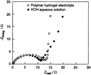
Potassium poly(acrylate), with chemical formula –(CH2–CHCOOR)n–, dissolves in water with a concomitant decrease in pH of the resultant solution. Estimation based on the dissociation equilibrium constant of acetic acid (pKa = 4.76) or propanoic acid (pKa = 4.89) suggests that >95 % of H+ are ion-exchanged by K+ at the R-sites in the above chemical formula.82PAAK-based hydrogels such as PAAK–KOH–H2O and PAAK–KCl–H2O could be classified as physical hydrogels as no chemical reaction is involved in their formation. Formation of PAAK-based physical hydrogels presumably takes place by ion-mediated network formation making them more stable than the corresponding PEO–KOH–H2O hydrogels. The degree of network formation depends upon the pH and ionic strength of the medium and also the type of counter ion and functional charge-density of the polymer.46 Iwakura et al.83,84 have prepared PAAK–KOH–H2O hydrogel electrolyte and subsequently employed them in Ni/MH batteries. Iwakura et al.,85 Nohara et al.,86 and Wada et al.87,88 have reported ECs employing alkaline cross-linked potassium poly(acrylate) hydrogel, namely PAAK–KOH–H2O, as electrolyte and compared the performance with an EC employing 10 M KOH aqueous electrolyte; the performances of the ECs are found to be similar. The ionic conductivity of the PAAK–KOH–H2O hydrogel electrolyte is reported to be comparable to that of KOH aqueous solution electrolyte over wide ranges of KOH concentrations and temperatures while the PEO–KOH–H2O hydrogel electrolyte exhibits low conductivity.81 The voltammograms for the ECs employing PAAK–KOH–H2O and aqueous 10 M KOH electrolytes recorded at a scan rate of 10 mV s−1 are shown in Fig. 3. Specific capacitances for the ECs, obtained from the CVs, are 150 and 144 F g−1 with PAAK–KOH–H2O and 10 M KOH aqueous electrolytes, respectively. The charge–discharge plots for both the ECs are observed to be nearly linear with little ohmic drop. This is ascribed to the high ionic-conductivity of the electrolytes and good electrical contact of the electrolytes with the carbon electrodes. The galvanostatic charge–discharge data for the ECs with PAAK–KOH–H2O and 10 M KOH aqueous electrolytes recorded at a current density of 1 mA cm−2 are shown in Fig. 4; the respective discharge capacitance values from these data are determined to be 146 and 142 F g−1 for the ECs. The discharge capacitance of the EC with polymer hydrogel electrolyte is 82% of the initial value after 20![[thin space (1/6-em)]](https://www.rsc.org/images/entities/char_2009.gif) 000 cycles, while it is 72% in the case of the EC with KOH aqueous solution electrolyte. This clearly indicates that EC assembled by using PAAK–KOH–H2O hydrogel electrolyte exhibits better performance than the EC employing 10 M KOH aqueous solution electrolyte, suggesting that the hydrogel polymer electrolyte prepared from PAAK with higher water holding capacity is more effective in maintaining good electrode/electrolyte interface than the aqueous alkaline electrolyte. To investigate the electrochemical behavior at the electrode/electrolyte interface in detail, ac impedance measurements have been carried out. The Nyquist plots for the ECs with cross-linked PAAK–KOH–H2O and 10 M KOH aqueous solution electrolytes are shown in Fig. 5. The equivalent series resistance values are estimated to be 0.14 and 0.12 Ω for PAAK–KOH–H2O and 10 M KOH aqueous solution electrolytes, respectively. Nohara et al.89 have reported the self-discharge characteristics of an EC using PAAK–KOH–H2O electrolyte. The EC has been found to exhibit lower voltage-decay on open circuit and lower leakage-current than the EC with KOH aqueous solution electrolyte. The same authors90have reported a hybrid EC assembled using activated carbon (AC) as negative electrode, Ni(OH)2 as positive electrode and PAAK–KOH–H2O as the electrolyte. The hybrid EC has been shown to operate over a wide potential range exhibiting ca. 2.4 times higher capacitance than the EC with two symmetrical AC electrodes.
000 cycles, while it is 72% in the case of the EC with KOH aqueous solution electrolyte. This clearly indicates that EC assembled by using PAAK–KOH–H2O hydrogel electrolyte exhibits better performance than the EC employing 10 M KOH aqueous solution electrolyte, suggesting that the hydrogel polymer electrolyte prepared from PAAK with higher water holding capacity is more effective in maintaining good electrode/electrolyte interface than the aqueous alkaline electrolyte. To investigate the electrochemical behavior at the electrode/electrolyte interface in detail, ac impedance measurements have been carried out. The Nyquist plots for the ECs with cross-linked PAAK–KOH–H2O and 10 M KOH aqueous solution electrolytes are shown in Fig. 5. The equivalent series resistance values are estimated to be 0.14 and 0.12 Ω for PAAK–KOH–H2O and 10 M KOH aqueous solution electrolytes, respectively. Nohara et al.89 have reported the self-discharge characteristics of an EC using PAAK–KOH–H2O electrolyte. The EC has been found to exhibit lower voltage-decay on open circuit and lower leakage-current than the EC with KOH aqueous solution electrolyte. The same authors90have reported a hybrid EC assembled using activated carbon (AC) as negative electrode, Ni(OH)2 as positive electrode and PAAK–KOH–H2O as the electrolyte. The hybrid EC has been shown to operate over a wide potential range exhibiting ca. 2.4 times higher capacitance than the EC with two symmetrical AC electrodes.
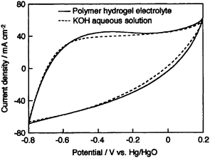 |
| | Fig. 3 Cyclic volammograms for the activated carbon fiber cloth electrode-based ECs employing PAAK–KOH–H2O hydrogel and 10 M KOH aqueous solution electrolytes recorded at 25 °C at a scan rate of 10 mV s−1 (from ref. 85). | |
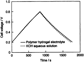 |
| | Fig. 4 Galvanostatic charge–discharge curves (200th cycle) for the activated carbon fiber cloth electrode-based ECs employing PAAK–KOH–H2O hydrogel and 10 M KOH aqueous solution electrolytes recorded at 25 °C at a current density of 1 mA cm−2 (from ref. 85). | |
 |
| | Fig. 5
Nyquist plots for the activated carbon fiber cloth electrode-based ECs with PAAK–KOH–H2O hydrogel and 10 M KOH aqueous solution electrolytes recorded at 25 °C at an ac amplitude of 5 mV rms in the frequency range between 1 mHz and 10 kHz (from ref. 85). | |
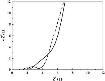
A PAAK-based neutral hydrogel electrolyte has been studied by Lee and Wu.82 A pseudocapacitor with MnO2·nH2O as the electrode and PAAK–KCl–H2O as the electrolyte has been assembled and its performance compared with a similar EC employing 1 M KCl aqueous solution as electrolyte. The PAAK–KCl–H2O hydrogel electrolyte along with a partially immersed MnO2·nH2O-based EC in a container in an inverted position is shown in Fig. 6. The CVs for the MnO2·nH2O-based ECs with 1 M KCl aqueous solution and PAAK–KCl–H2O hydrogel electrolytes are shown in Fig. 7(i) and Fig. 7(ii), respectively. Specific capacitance values of 168 and 116 F g−1 have been observed for the ECs with PAAK–KCl–H2O hydrogel and 1 M KCl aqueous solution electrolytes, respectively. The higher capacitance value for the hydrogel-based EC as compared to the EC employing aqueous KCl solution has been ascribed to the compatibility in the hydrophobicities of PVdF binder and PAAK. The hydrophobic nature of the polymeric component of the hydrogel electrolyte improves the compatibility between the PVdF binder component of the electrode matrix and the hydrogel electrolyte, resulting in good penetrability of the latter within the pores of electrodes. Consequently, the overall cell capacitance increases due to a decrease in the unwetted electrode area. Nyquist plots for the MnO2·nH2O-based ECs with PAAK–KCl–H2O hydrogel and 1 M KCl aqueous solution electrolytes are shown in Fig. 8. These plots exhibit characteristics of a porous pseudocapacitor. The similarity in charge-transfer resistances for the two electrolytes-based ECs suggests that the electrochemical processes at the oxide–electrolyte interface are comparable in the two types of electrolytes. Hence, PAAK-based electrolytes seem to be good candidates to be used in conjunction with other electrode materials such as RuO2·xH2O, carbon, MnO2 for pseudocapacitors as well as hybrid capacitors.
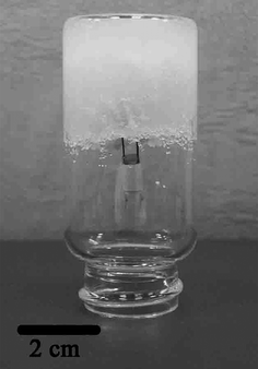 |
| | Fig. 6 The PAAK–KCl–H2O hydrogel electrolyte along with a partially immersed MnO2·nH2O-based EC in a container in an inverted position (from ref. 82). | |
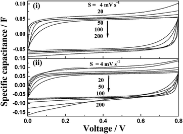 |
| | Fig. 7 Cyclic volammograms for the MnO2·nH2O-based ECs employing (i) 1 M KCl aqueous solution and (ii) PAAK–KCl–H2O hydrogel electrolytes (from ref. 82). | |
 |
| | Fig. 8
Nyquist plots for the MnO2·nH2O-based ECs with PAAK–KCl–H2O hydrogel (dashed line) and 1 M KCl aqueous solution (solid line) electrolytes recorded in the frequency range between 5 mHz and 60 kHz with a perturbation of 10 mV rms (from ref. 82). | |
2.3.
Poly(vinyl alcohol) hydrogel electrolytes
An EC employing an activated carbon fiber cloth electrode and a hydrogel electrolyte comprising aqueous PVA cross-linked with glutaraldehyde has been reported by Wada et al.91 and its performance compared with a similar EC employing 1 M H2SO4 aqueous solution electrolyte. The ionic conductivity of the cross-linked PVA hydrogel electrolyte (PHE) has been found to be comparable to that of 1 M H2SO4 aqueous solution. The galvanostatic charge–discharge data for the ECs with cross-linked PHE and 1 M H2SO4 aqueous solution electrolyte are shown in Fig. 9. Discharge capacitance values of 110 and 115 F g−1 have been found for the ECs with cross-linked PVA hydrogel electrolyte (PHE) and 1 M H2SO4 aqueous solution electrolyte, respectively. To monitor the self-discharge characteristics, the ECs are initially charged to 0.8 V and the time course of the cell voltage under an open circuit condition is recorded. The open circuit voltage–time decay data for the ECs with cross-linked PHE and 1 M H2SO4 aqueous solution, after charging to 0.8 V, are shown in Fig. 10. As seen from Fig. 10, the open-circuit voltage–time decay for the cross-linked PHE-based EC is lower than that for the EC with 1 M H2SO4 aqueous solution electrolyte. This implies that the PHE-based EC exhibits lower self-discharge than the EC employing 1 M H2SO4 aqueous solution as electrolyte.
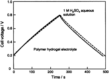 |
| | Fig. 9 Galvanostatic charge–discharge curves for the activated carbon fiber cloth electrode-based ECs employing PVA hydrogel and 1 M H2SO4 aqueous solution electrolytes recorded at a current density of 1 mA cm−2 (from ref. 91). | |
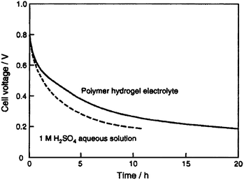 |
| | Fig. 10 Open-circuit voltage vs. time plots for the activated carbon fiber cloth electrode-based ECs with PVA hydrogel and 1 M H2SO4 aqueous solution electrolytes (from ref. 91). | |
Studies on acidic, alkaline and neutral poly(vinyl alcohol)/poly(acrylic acid) blend hydrogel electrolytes (BHEs) and their application to ECs have been reported by Choudhury et al.54 Ionic conductivity data as a function of polymer composition for the PVA/PAA BHE with: (a) HClO4, (b) NaOH, and (c) NaCl dopant are shown in Fig. 11. The ionic conductivity of the acidic PVA/PAA BHEs decreases with increase in the proportion of PAA in the blend while that of the alkaline and neutral PVA/PAA BHEs exhibit a reverse effect. This contrasting behavior has been explained based on the assumption that proton conduction in the acidic PVA/PAA BHE occurs by the Grötthus-type mechanism whereas the ionic conductivity in alkaline as well as neutral PVA/PAA BHEs is brought about predominantly by segmental motion.
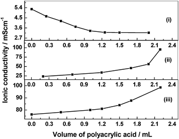 |
| | Fig. 11 Ionic conductivity as a function of polymer composition for the PVA/PAA blend hydrogel electrolyte with (i) HClO4, (ii) NaOH, and (iii) NaCl dopant (from ref. 54). | |
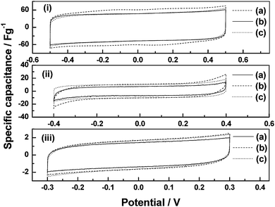
The cyclic voltammograms for the ECs with black pearl carbon (BPC) electrodes and PVA/PAA BHEs comprising: (a) PVA : PAA = 5 : 0, (b) PVA : PAA = 4 : 1, and (c) PVA : PAA = 3 : 2 by volume, in (i) acidic, (ii) alkaline, and (iii) neutral forms are shown in Fig. 12. With increasing proportion of PAA in the blend, the specific capacitance values for the acidic BHE-based ECs decrease while those for the alkaline and neutral BHE-based ECs increase. The variation in specific capacitance values with polymer composition for the ECs employing acidic, alkaline and neutral BHEs follow the same trend as that observed in the variation of ionic conductivity with polymer composition for the three types of BHEs.
 |
| | Fig. 12
Cyclic voltammograms for ECs employing BPC electrodes and PVA/PAA blend hydrogel electrolytes comprising (a) PVA : PAA = 5 : 0, (b) PVA : PAA = 4 : 1, and (c) PVA : PAA = 3 : 2 with (i) HClO4, (ii) NaOH, and (iii) NaCl dopant (from ref. 54). | |
To investigate the effect of variation of HClO4 dopant concentration on specific capacitance of the ECs, CVs have been recorded for ECs comprising BPC electrodes and PHEs with 0.1, 0.5, 1.0, 1.5 and 2.0 N HClO4 dopants and the data are shown as (a), (b), (c), (d) and (e) in Fig. 13, respectively.92 The specific capacitance value at 0 V increases from 13.4 to 95.6 F g−1 as the concentration of HClO4 in the PHE is increased from 0.1 to 2.0 N. The increase in specific capacitance with increasing dopant concentration is explained on the basis of increased accessibility of the electrode surface by increased amount of dopant ions during potential cycling. In order to probe the effect of variation in HClO4 concentration on phase angle, electrochemical impedance data have been recorded for ECs comprising BPC electrodes and PHEs with 0.1, 0.5, 1.0, 1.5 and 2.0 N HClO4 dopants and the data are shown as (a), (b), (c), (d) and (e) in Fig. 14, respectively.92 The phase angle at 1 Hz increases from 76° to 79° as the concentration of HClO4 in the PHE is increased from 0.1 to 2.0 N. The increase in phase angle with increasing dopant concentration suggests an improvement in the capacitive behavior of the ECs. To study the effect of variation in HClO4 concentration on discharge capacitance and coulombic efficiency, galvanostatic chronopotentiometric data for the ECs with PHEs containing 0.1, 0.5, 1.0, 1.5 and 2.0 N HClO4 have been recorded and the data are shown as (a), (b), (c), (d) and (e), in Fig. 15, respectively.92 An increase in both charge and discharge times is observed with increasing HClO4 concentration in the PHE. The unequal time-scales associated with the first few cycles of the charge and discharge processes for ECs need to be probed further. The discharge capacitance increases from 8.7 to 96.8 F g−1 as the concentration of HClO4 in the PHE is increased from 0.1 to 2.0 N. As the concentration of HClO4 in the PHE is increased from 0.1 to 1.5 N, the coulombic efficiency of the ECs is found to increase from 85.9 to 87.5 %. With further increase in concentration of HClO4 in the PHE to 2.0 N, the coulombic efficiency decreases to 76.5 %. The data pertaining to the electrochemical studies depicted in Fig. 13–15 are summarized in Table 1.92
Table 1 Electrochemical data for the ECs comprising BPC electrodes and PVA hydrogel electrolytes with varying HClO4 concentrations (ref. 92)
| HClO4 concentration/M |
Electrochemical data obtained from |
| CVs at 0 V |
CVs by integrating total enclosed area |
Bode plot at 1 Hz |
Galvanostatic chronopotentiometry at 0.5 mA |
| Specific capacitance/F g−1 |
Average specific capacitance/F g−1 |
Phase angle/° |
Specific capacitance/F g−1 |
Charge–discharge efficiency (%) |
| 0.1 |
13.4 |
12.8 |
76.3 |
8.7 |
85.9 |
| 0.5 |
19.3 |
18.0 |
77.9 |
11.1 |
85.8 |
| 1.0 |
27.1 |
26.5 |
77.6 |
25.2 |
87.4 |
| 1.5 |
38.7 |
38.5 |
82.0 |
59.3 |
87.5 |
| 2.0 |
95.6 |
91.2 |
78.5 |
96.8 |
76.5 |
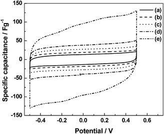 |
| | Fig. 13
Cyclic voltammograms for ECs employing BPC electrodes and pristine PVA hydrogel electrolytes containing (a) 0.1, (b) 0.5, (c) 1.0, (d) 1.5 and (e) 2.0 N HClO4 dopants (from ref. 92). | |
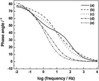 |
| | Fig. 14 Electrochemical impedance data for ECs employing BPC electrodes and pristine PVA hydrogel electrolytes containing (a) 0.1, (b) 0.5, (c) 1.0, (d) 1.5 and (e) 2.0 N HClO4 dopants (from ref. 92). | |
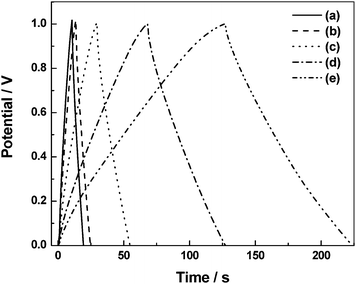 |
| | Fig. 15 Galvanstatic chronopotentiometric data for ECs employing BPC electrodes and pristine PVA hydrogel electrolytes containing (a) 0.1, (b) 0.5, (c) 1.0, (d) 1.5 and (e) 2.0 N HClO4 dopants (from ref. 92). | |
The PVA/PAA based materials are also amenable for fabricating pseudocapacitors using transition metal oxides. Capacitors employing RuOx·xH2O/C electrodes and acidic PVA/PAA BHEs with varying polymer composition54 show voltammograms [(a) PVA : PAA = 5 : 0, (b) PVA : PAA = 4 : 1, and (c) PVA : PAA = 3 : 2 by volume, Fig. 16] that are nearly rectangular in shape. A decrease in specific capacitance with increasing proportion of PAA in the blend is observed. The variation in specific capacitance of the RuOx·xH2O/C electrode-based ECs employing acidic BHEs follows the same trend as that observed for the ionic conductivity of the acidic BHEs as a function of polymer composition in the blend. A maximum specific capacitance value of ca. 1000 F g−1 is obtained for the pristine acidic PHE. Electrochemical impedance data for a typical EC with RuOx·xH2O/C electrodes and acidic pristine PVA hydrogel electrolyte recorded in the frequency range between 5 mHz and 10 kHz with a perturbation of 5 mV rms show a charge-transfer resistance of ca. 32 Ω and a phase angle of ca. 82°. The electrochemical impedance data for a typical EC with RuOx·xH2O/C electrodes and acidic pristine PVA hydrogel electrolyte are analyzed to evaluate the relaxation time constant of the EC. Plots of normalized imaginary part |Q|/|S| and real part |P|/|S| of the complex power (S) vs. frequency data for a typical EC with RuOx·xH2O/C electrodes and acidic pristine PVA hydrogel electrolyte are shown in Fig. 17. The relaxation time constant is found to be ca. 0.33 s. Yong-gang and Xiao-gang3 have reported a pseudocapacitor based on PVA–H3PO4–H2O hydrogel as electrolyte and RuO2/TiO2nanotube composites as electrodes. A maximum specific capacitance of 1263 F g−1 is obtained for the RuO2 loaded on TiO2. It is noteworthy that gluteraldehyde-cross-linked-PVA hydrogels being chemically cross-linked are more stable than both PEO and PAAK-based physical hydrogels.
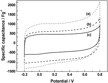 |
| | Fig. 16
Cyclic voltammograms for ECs employing RuOx·xH2O/C electrodes and acidic PVA/PAA blend hydrogel electrolytes comprising (a) PVA : PAA = 5 : 0, (b) PVA : PAA = 4 : 1, and (c) PVA : PAA = 3 : 2 (from ref. 54). | |
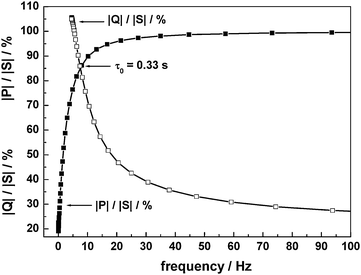 |
| | Fig. 17 Plots of normalized reactive power |Q|/|S| and active power |P|/|S|vs. frequency for an EC with RuOx·xH2O/C electrodes and acidic pristine PVA hydrogel electrolyte (from ref. 54). | |
2.4. Gelatin hydrogel electrolytes
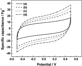
Gelatin is a polypeptide consisting mostly of proline, hydroxyproline and glycine. It is extracted from denatured collagen. It dissolves in boiling water to form a pale yellow, semi-transparent, viscous solution. On cooling below 308 K, a concentrated solution of gelatin forms a physical hydrogel. The utility of such a hydrogel is limited due to its low network rigidity. The mechanical strength of gelatin hydrogel is improved by chemical cross-linking with aldehydes.56 Choudhury et al.93 have reported the use of a hydrogel electrolyte comprising aqueous gelatin cross-linked with glutaraldehyde in ECs. The effect of variation in concentration of NaCl dopant on specific capacitance has been followed using cyclic voltammetry. Fig. 18 shows that the specific capacitance increases from 37.6 to 81.2 F g−1 as the concentration of NaCl in the GHEs is increased from 0 to 3 N. The increase in capacitance with increasing dopant concentration has been explained on the basis of increased accessibility of BPC by dopant ions during charge-discharge cycling. The low concentration of ions present in pristine GHE is not sufficient to access all the active sites of BPC that possess high surface-area. With increasing dopant concentration, there is a corresponding increase in the number of ions available for electric-double-layer formation at the electrode/electrolyte interface, leading to a better utilization of BPC electrode material in the ECs with doped GHEs as compared to pristine GHE-based ECs. The enhanced utilization of electrode material in the ECs with doped GHEs is responsible for enhanced specific capacitance of the latter. The effect of variation in concentration of NaCl on phase angle of ECs comprising BPC electrodes and GHEs as studied by electrochemical impedance is shown in Fig. 19. The phase angle of ECs at 1 Hz increases from 49 to 75° as the concentration of NaCl in the GHE is increased from 0 to 3 N. The charge–discharge data as recorded by galvanostatic chronopotentiometry for GHEs containing varying concentrations of NaCl are shown in Fig. 20. The discharge capacitance increases from 12.4 to 70 F g−1 as the concentration of NaCl in the GHE is increased from 0 to 3 N. The data pertaining to the electrochemical studies depicted in Fig. 18–20 are summarized in Table 2.
Table 2 Electrochemical data for the ECs comprising BPC electrodes and gelatin hydrogel electrolytes with varying NaCl concentrations (ref. 93)
|
NaCl concentration/N |
Electrochemical data obtained from |
| CVs at 0 V |
CVs by integrating total enclosed area |
Bode plot at 1 Hz |
Galvanostatic chronopotentiometry at 0.1 mA |
| Specific capacitance/F g−1 |
Average specific capacitance/F g−1 |
Phase angle/° |
Specific capacitance/F g−1 |
| 0 |
37.6 |
35.6 |
49 |
12.4 |
| 1 |
58 |
58.8 |
65 |
31.2 |
| 2 |
70.4 |
69.6 |
71 |
56.8 |
| 3 |
81.2 |
82.4 |
75 |
70 |
 |
| | Fig. 18
Cyclic voltammograms recorded at a scan rate of 5 mV s−1 for the ECs comprising BPC electrodes and GHEs containing (a) 0, (b) 1, (c) 2, and (d) 3 N NaCl dopants (from ref. 93). | |
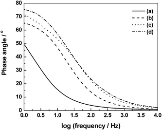 |
| | Fig. 19 Electrochemical impedance data recorded in the frequency range between 1 Hz and 10 kHz at an ac amplitude of 5 mV rms for the ECs comprising BPC electrodes and GHEs with (a) 0, (b) 1, (c) 2, and (d) 3 N NaCl dopants (from ref. 93). | |
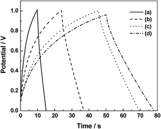 |
| | Fig. 20 Galvanstatic chronopotentiometric data recorded at a current density of 0.1 mA cm−2 for the ECs comprising BPC electrodes and GHEs containing (a) 0, (b) 1, (c) 2, and (d) 3 N NaCl dopants (from ref. 93). | |
The discharge capacitance, coulombic efficiency and cell resistance data for the ECs comprising pristine as well as 3 N NaCl-doped GHEs are studied as a function of charge–discharge cycles and the data93 are shown in Fig. 21–23. As shown in Fig. 21, the EC with 3 N NaCl-doped GHE has a higher discharge-capacitance of 10.4 F g−1 as against 5.2 F g−1 observed for pristine GHE-based EC. As shown in Fig. 22, the coulombic efficiencies for the ECs with both pristine and 3 N NaCl-doped GHEs are as low as ca. 50% for the first charge–discharge cycle, which gradually increase to ca. 85% for the one hundredth cycle. The EC with 3 N NaCl-doped GHE has nominally higher coulombic efficiency as compared to the EC with pristine GHE. As shown in Table 3, the coulombic efficiency increases from 52 to 100% as the current density increases from 0.1 to 1.0 mA cm−2. As the current density increases, the time required to attain the cut-off voltage of 1 V decreases affecting the formation of the electric double-layer leading to an increase in coulombic efficiency of the ECs.94 As shown in Fig. 23, the cell resistance for the EC with 3 N NaCl doped GHE is ca. 1.2 Ω as compared to ca. 36 Ω for the EC with pristine GHE before recording charge–discharge cycles. The lower cell resistance for the doped GHE-based EC as compared to the pristine GHE-based EC is mainly due to the higher ionic conductivity for the doped GHE in relation to the pristine GHE. The discharge capacitance and coulombic efficiency decrease while cell resistance increases with increasing charge–discharge cycle number. The EC with 3 N NaCl doped GHE exhibits a longer life of ca. 4.7 h over 900 charge–discharge cycles as against the EC with pristine GHE that has an endurance of only ca. 4.3 h over 1700 cycles.
Table 3 Average specific capacitance values for pristine GHE-based ECs evaluated by keeping it in a closed chamber maintained at 100% relative humidity (ref. 93)
| Time/day |
0 |
1 |
2 |
3 |
4 |
5 |
6 |
7 |
8 |
9 |
10 |
| Average specific- capacitance/F g−1 |
43.6 |
40.8 |
37.6 |
36.4 |
36.0 |
36.8 |
36.8 |
37.6 |
37.6 |
37.6 |
38.0 |
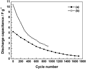 |
| | Fig. 21 Plots of specific capacitance, evaluated from galvanstatic chronopotentiometric data recorded at a current density of 0.1 mA cm−2, as a function of charge–discharge cycles for the ECs comprising BPC electrodes and GHEs containing (a) 0 and (b) 3 N NaCl (from ref. 93). | |
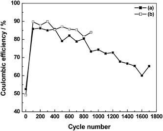 |
| | Fig. 22 Plots of coulombic efficiency, evaluated from galvanstatic chronopotentiometric data recorded at a current density of 0.1 mA cm−2, as a function of charge–discharge cycles for the ECs with GHEs containing (a) 0 and (b) 3 N NaCl (from ref. 93). | |
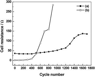 |
| | Fig. 23 Plots of cell resistance, evaluated from electrochemical impedance data recorded in the frequency range between 100 mHz and 10 kHz with a perturbation of 5 mV rms, as a function of charge–discharge cycles for the ECs with GHEs containing (a) 0 and (b) 3 N NaCl (from ref. 93). | |
Ionic conduction in pristine GHE takes place by the Grötthus-type mechanism of proton transport whereas that in NaCl-doped GHEs occurs predominantly by free diffusion of hydrated Na+ and Cl− ions. As described in the literature,54transport of protons in aqueous media by a Grötthus-type mechanism takes place along chains of hydrogen bonded water molecules. In this mechanism, protons are transported by alternation of covalent and hydrogen bonds with little physical movement. This mechanism explains the facile proton transport and accounts for its highest conductivity among all the ions. Na+ and Cl− ions in aqueous media such as doped GHEs are associated with large hydration-shells. During charge–discharge cycling of ECs, Na+ and Cl− ions with their large shells of hydrated water molecules shuttle back and forth between the electrodes. The ionic shuttling in ECs takes place at high rates owing to their high power-density. Because of the fast potential-driven migration of hydrated Na+ and Cl− ions back and forth between the electrodes during charge–discharge cycling, the NaCl-doped GHEs degrade faster than pristine GHEs with a consequent sharp increase in cell resistance for the NaCl-doped GHE-based ECs as shown in Fig. 23. The decrease in both the discharge capacitance and coulombic efficiency values with concomitant increase in cell resistance for the ECs during charge–discharge cycling is due to the gradual evaporation of water from the GHEs. This can be substantiated from the study of the EC performance as a function of time during which the EC is kept under open-circuit condition in a closed chamber maintained at 100% relative humidity. There is only a small decrease in discharge capacitance during the first 50 h of operation subsequent to which the performance is almost invariable. The capacitive performance data for the pristine GHE-based EC for 10 days of continuous operation are summarized in Table 3. It is noteworthy that unlike the synthetic-polymer-based hydrogel electrolytes, biopolymer-based hydrogel electrolytes with natural cross-linkers, such as genipin,39 have a unique advantage for applications in biomedical devices such as defibrillators.9 They are also presently shown to exhibit excellent performance in electrochemical energy systems.
3. Inorganic hydrogel electrolytes
Inorganic hydrogels prepared by the sol–gel method are one of the most promising host materials to design high proton-conducting composites. Unlike organic polymer-based hydrogels, silica hydrogels incorporating perchloric acid and heteropoly acid dopants have been found to possess ionic conductivity values as high as 10−2 S cm−1 under ambient conditions as they contain a large number of micropores and mesopores filled with liquid which facilitate fast proton-transport. Perchloric acid-doped silica hydrogels containing PVA as a binder have been prepared by a sol–gel method and employed95 in all solid-state ECs along with activated carbon as the electrode. The dependence of room temperature ionic conductivity for the silica hydrogel electrolyte on HClO4 concentration is shown in Fig. 24. The conductivity of the silica hydrogel electrolyte increases with increasing HClO4 concentration attaining the maximum value of 5 × 10⁻² S cm−1 at room temperature for a HClO4/TEOS molar ratio of 1. The variation of IR-drop with varying discharge current for an all solid-state EC fabricated employing silica-hydrogel electrolyte with an HClO4/TEOS molar ratio of 0.5 is shown in Fig. 25. The IR-drop has been found to be almost directly proportional to the discharge current. Variation in specific capacitance for the ECs comprising PVA-containing silica hydrogel electrolytes as a function of HClO4 concentration is depicted in Fig. 26. The room-temperature specific capacitance of the EC drastically increases with an increase in HClO4 concentration and tends to attain a value of 44 F g−1 for a HClO4/TEOS molar ratio of 0.5. The large capacitance of the all solid-state ECs is attributed to the high proton conductivity of the hydrogel electrolyte and the homogeneous hybridization of the activated carbon and the hydrogels.
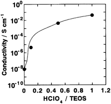 |
| | Fig. 24 Variation in ionic conductivity of PVA-containing silica hydrogel electrolytes as a function of HClO4 dopant concentration (from ref. 95). | |
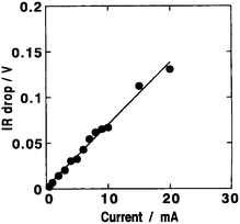 |
| | Fig. 25 Variation in IR-drop with discharge current for an EC employing PVA-containing silica hydrogel electrolyte with a typical HClO4/TEOS molar ratio of 0.5 and activated carbon powder hybridized with silica hydrogel as polarizable electrode (from ref. 95). | |
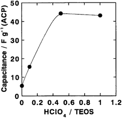 |
| | Fig. 26 Variation in specific capacitance for ECs comprising PVA-containing silica hydrogel electrolytes with varying HClO4 dopant concentrations and activated carbon powder hybridized with silica hydrogel as polarizable electrode (from ref. 95). | |
4. Summary
Hydrogel-electrolyte-based all solid-state ECs are promising and environment-friendly energy-storage devices. Among the various alkaline polymer-hydrogel-electrolyte-based ECs, cross-linked PAAK–KOH–H2O based-EC with activated carbon fiber cloth electrodes exhibits a specific capacitance value as high as 150 F g−1. A pseudocapacitor employing a MnO2·nH2O electrode and a neutral hydrogel-polymer-electrolyte, namely PAAK–KCl–H2O, yields higher specific capacitance values of ca. 168 F g−1. ECs with chemical hydrogel electrolytes, namely cross-linked PVA and gelatin-based hydrogel electrolytes, are both mechanically and chemically very stable as compared to ECs with conventional non-cross-linked hydrogel-polymer-electrolytes and hence are very promising. ECs employing acidic cross-linked PVA hydrogel electrolyte and activated carbon fiber cloth electrodes remain limited to specific capacitance values of only about 110 F g−1. However, optimization of various physical parameters is desired to achieve optimum specific capacitance values with these ECs. Interestingly, cross-linked PVA hydrogel electrolytes can be prepared with acidic, alkaline and neutral dopants. BHEs consisting of PVA/PAA blend show interesting behavior in relation to polymer composition. With increasing proportion of PAA in the PVA/PAA BHEs, both ionic conductivity and specific capacitance values for the acidic BHE-based ECs decrease while those for the alkaline and neutral BHE-based ECs increase. A pseudocapacitor employing RuOx·xH2O/C electrode and acidic pristine PVA hydrogel electrolyte exhibits a specific capacitance value as high as 1000 F g−1. Biopolymer-based hydrogel electrolytes such as cross-linked gelatin hydrogel electrolytes are highly hydrophilic in nature and possess a better water-retention capacity as compared to synthetic polymers such as PVA-based hydrogel electrolytes. Silica hydrogel-based inorganic hydrogel electrolytes are attractive materials for application in ECs. Silica-based hydrogel electrolytes have been found to exhibit ionic conductivity values as high as 10−2 S cm−1 and specific capacitance values as high as 44 F g−1 at room temperature. The use of physical hydrogels, such as gelatin, agar, starch, collagen, and gellan gum, and also chemical hydrogels, namely chitosan, polyester, and polyamide, as electrolytes in ECs needs to be explored. Other hydrogels based on organic compounds such as bile acids are to be explored for electrochemical applications, particularly capacitors.96 In this article, we have limited the discussion only to the use of polymeric materials as electrolytes for ECs. It is noteworthy that the use of polymeric materials as electrodes in ECs is well documented in the literature.4,24–26
References
-
B. E. Conway, Electrochemical Supercapacitors: Scientific Fundamentals and Technological Applications, Kluwer Academic Publishers/Plenum Press, New York, 1999 Search PubMed.
- M. Winter and R. J. Brodd, Chem. Rev., 2004, 104, 4245 CrossRef CAS.
- W. Yong-gang and Z. Xiao-gang, Electrochim. Acta, 2004, 49, 1957 CrossRef CAS.
- A. Burke, J. Power Sources, 2000, 91, 37 CrossRef CAS.
- E. Frackowiak and F. Béguin, Carbon, 2001, 39, 937 CrossRef CAS.
- J. Gamby, P. L. Taberna, P. Simon, J. F. Fauvarque and M. Chesneau, J. Power Sources, 2001, 101, 109 CrossRef.
- S. T. Mayer, R. W. Pekala and J. L. Kaschmitter, J. Electrochem. Soc., 1993, 140, 446 CAS.
- R. W. Pekala, J. C. Farmer, C. T. Alviso, T. D. Tran, S. T. Mayer, J. M. Miller and B. Dunn, J. Non-Cryst. Solids, 1998, 225, 74 CrossRef CAS.
- J. Wang, S. Q. Zhang, Y. Z. Guo, J. Shen, S. M. Attia, B. Zhou, G. Z. Zeng and Y. S. Gui, J. Electrochem. Soc., 2001, 148, D75 CrossRef CAS.
- E. Frackowiak, K. Meternier, V. Bertagna and F. Béguin, Appl. Phys. Lett., 2000, 77, 2421 CrossRef CAS.
- E. Frackowiak, K. Jurewicz, S. Delpeux and F. Béguin, J. Power Sources, 2001, 97–98, 822 CrossRef CAS.
- S. Mitra and S. Sampath, Electrochem. Solid-State Lett., 2004, 7, A264 CrossRef CAS.
- B. E. Conway, J. Electrochem. Soc., 1991, 138, 539.
- S. Sarangapani, B. V. Tilak and C. P. Chen, J. Electrochem. Soc., 1996, 143, 3791 CAS.
- J. P. Zheng, P. J. Cygan and T. R. Jow, J. Electrochem. Soc., 1995, 142, 2699 CAS.
- V. Srinivasan and J. W. Weidner, J. Electrochem. Soc., 2000, 147, 880 CrossRef CAS.
- T. Kudo, Y. Ikeda, T. Watanabe, M. Hibino, M. Miyayama, H. Abe and K. Kajita, Solid State Ionics, 2002, 152–153, 833 CrossRef CAS.
- Y. U. Jeong and A. Manthiram, Electrochem. Solid-State Lett., 2000, 3, 205 CAS.
- A. Yamada and J. B. Goodenough, J. Electrochem. Soc., 1998, 145, 737 CAS.
- H. Y. Lee and J. B. Goodenough, J. Solid State Chem., 1999, 144, 220 CrossRef CAS.
- H. P. Stadniychuk, M. A. Anderson and T. W. Chapman, J. Electrochem. Soc., 1996, 143, 1629 CrossRef CAS.
- J. J. Xu, A. J. Kinser, B. B. Owens and W. H. Smyrl, Electrochem. Solid-State Lett., 1998, 1, 1 CrossRef CAS.
- M. Mastragostino, C. Arbizzani and F. Soavi, Solid State Ionics, 2002, 148, 493 CrossRef CAS.
- S. Ghosh and O. Inganäs, Adv. Mater., 1999, 11, 1214 CrossRef CAS.
- E. Frackowiak, V. Khomenko, K. Jurewicz, K. Lota and F. Béguin, J. Power Sources, 2006, 153, 413 CrossRef CAS.
- P. Gómez-Romero, M. Chojak, K. Cuentas-Gallegos, J. A. Asensio, P. J. Kulesja, N. Casañ-Pastor and M. Lira-Cantú, Electrochem. Commun., 2003, 5, 149 CrossRef CAS.
-
Polymer Electrolyte
Review, ed. J. R. MacCallum and C. A. Vincent, Elsevier, London, 1987–1989, vol. 1/2 Search PubMed.
-
F. M. Gray, in Solid Polymer Electrolytes, ed. F. M. Gray, VCH, New York, 1991 Search PubMed.
- F. B. Dias, L. Plomp and J. B. J. Veldhuis, J. Power Sources, 2000, 88, 169 CrossRef CAS.
- D. E. Fenton, J. M. Parker and P. V. Wright, Polymer, 1973, 14, 589 CAS.
- P. V. Wright, Br. Polym. J., 1975, 7, 319 CrossRef CAS.
-
M. B. Armand, S. M. Chabagno and M. Duclot, in Second International Meeting on Solid Electrolytes, St. Andrews, Scotland, Extended Abstracts, 20–22 Sept., 1978 Search PubMed.
- A. Bhide and K. Hariharan, J. Power Sources, 2006, 159, 1450 CrossRef CAS.
- C. Bertier, W. Gorecki, M. Minier, M. B. Armand, J. M. Chabagno and P. Rigaud, Solid State Ionics, 1983, 11, 91 CrossRef CAS.
- G. Feullade and P. Perche, J. Appl. Electrochem., 1975, 5, 63 CAS.
- T. Nagatomo, C. Ichikawa and O. Omato, J. Electrochem. Soc., 1987, 134, 305 CrossRef CAS.
- F. Croce, F. Gerace, G. Dautzemberg, S. Passerini, G. B. Appetecchi and B. Scrosati, Electrochim. Acta, 1994, 39, 2187 CrossRef CAS.
- D. Peramunage, D. M. Pasquqriello and K. M. Abraham, J. Electrochem. Soc., 1995, 142, 1789 CAS.
- M. Alamgir and K. M. Abraham, J. Electrochem. Soc., 1993, 140, L96 CrossRef CAS.
- H. S. Choe, J. Giaccai, M. Alamgir and K. M. Abraham, Electrochim. Acta, 1995, 40, 2289 CrossRef CAS.
- I. Kuribayashi, M. Yamashita, S. Muraoka and K. Nagasawa, J. Power Sources, 1996, 63, 121 CrossRef CAS.
- G. G. Cameron, M. D. Ingram and K. Sarmouk, Eur. Polym. J., 1990, 26, 1097 CrossRef CAS.
-
M. Alamgir and K. M. Abraham, in Lithium Batteries—New Materials, Developments and Perspectives, ed. G. Pistoia, Elsevier, 1994, p. 93, ch. 3 Search PubMed.
-
O.-M. Hyun, J.-H. Park, Y.-J. Shin and J.-M. Oh, in The 1997 Joint International Meeting, The Electrochemical Society and The International Society of Electrochemistry, August 31–September 5, Paris, Meeting Abstracts, vol. 97/21997, (Fall), Abs. No. 117, p. 129 Search PubMed.
- N. A. Peppas, P. Bures, W. Leobandung and H. Ichikawa, Eur. J. Pharm. Biopharm., 2000, 50, 27 CrossRef CAS.
- K. R. Kamath and K. Park, Adv. Drug Deliv. Rev., 1993, 11, 59 CrossRef CAS.
- A. Lewandowski, K. Skorapaka and J. Malinska, Solid State Ionics, 2000, 133, 265 CrossRef CAS.
- R. A. Vargas, V. H. Zapata, E. Matallana and M. A. Vargas, Electrochim. Acta, 2001, 46, 1699 CrossRef CAS.
- J. W. Rhim, H. S. Hwang, D. S. Kim, H. B. Park, C. H. Lee, Y. M. Lee, G. Y. Moon and S. Y. Nam, Macromol. Res., 2005, 13, 135 Search PubMed.
- M. S. Kang, J. H. Kim, J. Won, S. H. Moon and Y. S. Kang, J. Membr. Sci., 2005, 247, 127 CrossRef CAS.
- A. M. Araujo, M. T. Neves, W. M. Azevedo, G. G. Oliveira, D. L. Ferreira, R. A. L. Coelho, E. A. P. Figueiredo and L. B. Carvalho, Biotechnol. Tech., 1997, 11, 67 CrossRef CAS.
- J. Qiao, T. Hamaya and T. Okada, J. Mater. Chem., 2005, 15, 4414 RSC.
- S. Y. Kim, H. S. Shin, Y. M. Lee and C. N. Jeong, J. Appl. Polym. Sci., 1999, 73, 1675 CrossRef CAS.
- N. A. Choudhury, A. K. Shukla, S. Sampath and S. Pitchumani, J. Electrochem. Soc., 2006, 153, A614 CrossRef CAS.
- C. O. Dasenbrock, T. H. Ridgway, C. J. Seliskar and W. R. Heineman, Electrochim. Acta, 1998, 43, 3497 CrossRef CAS.
- M. T. Nickerson, A. T. Paulson, E. Wagar, R. Farnworth, S. M. Hodge and D. Rousseau, Food Hydrocolloids, 2006, 20, 1072 CrossRef CAS.
- C.-H. Yao, B.-S. Liu, C.-J. Chang, S.-H. Hsu and Y.-S. Chen, Mater. Chem. Phys., 2004, 83, 204 CrossRef CAS.
- E. Schacht, M. Nobels, N. Vansteenkiste, J. Demeester, J. Franssen and A. Lemahieu, Polym. Gels Networks, 1993, 1, 213 CrossRef CAS.
- S.-F. Wang, T. Chen, Z.-L. Zhang, D.-W. Pang and K.-Y. Wong, Electrochem. Commun., 2007, 9, 1709 CrossRef CAS.
- L. Shen and P. He, Electrochem. Commun., 2007, 9, 657 CrossRef CAS.
- R. Yan, F. Zhao, J. Li, F. Xiao, S. Fan and B. Zeng, Electrochim. Acta, 2007, 52, 7425 CrossRef CAS.
- Y.-X. Sun, J.-T. Zhang, S.-W. Huang and S.-F. Wang, Sens. Actuators, B, 2007, 124, 494 CrossRef.
- X. Zeng, W. Wei, X. Li, J. Zeng and L. Wu, Bioelectrochemistry, 2007, 71, 135 CrossRef CAS.
- H.-H. Liu, Z.-Q. Tian, Z.-X. Lu, Z.-L. Zhang, M. Zhang and D.-W. Pang, Biosens. Bioelectron., 2004, 20, 294 CrossRef CAS.
- H.-H. Liu, Y.-Q. Wan and G.-L. Zou, J. Electroanal. Chem., 2006, 594, 111 CrossRef CAS.
- S. Wei, W. Dandan, G. Ruifang and Jiao Kui, Electrochem. Commun., 2007, 9, 1159 CrossRef.
- H. Lu, Z. Li and N. Hu, Biophys. Chem., 2003, 104, 623 CrossRef CAS.
- H. Huang, N. Hu, Y. Zeng and G. Zhou, Anal. Biochem., 2002, 308, 141 CrossRef CAS.
- X. Zhang, S. Wang, M. Hu and Y. Xiao, Biosens. Bioelectron., 2006, 21, 2180 CAS.
- L. Shen, R. Huang and N. Hu, Talanta, 2002, 56, 1131 CrossRef CAS.
- P. Staiti, M. Minutoli and F. Lufrano, Electrochim. Acta, 2002, 47, 2795 CrossRef CAS.
- F. Lufrano and P. Staiti, Electrochim. Acta, 2004, 49, 2683 CrossRef CAS.
- K.-W. Park, H.-J. Ahn and Y.-E. Sung, J. Power Sources, 2002, 109, 500 CAS.
- W.-J. Kim and D.-W. Kim, Electrochim. Acta, 2008, 53, 4331 CAS.
- D.-W. Kim, J. M. Ko, W. J. Kim and J. H. Kim, J. Power Sources, 2006, 163, 300 CrossRef CAS.
- P. Sivaraman, V. R. Hande, V. S. Mishra, Ch. Srinivasa Rao and A. B. Samui, J. Power Sources, 2003, 124, 351 CrossRef CAS.
- J. F. Fauvarque, S. Guinot, N. Bouzir, E. Salmon and J. F. Penneau, Electrochim. Acta, 1995, 40, 2449 CrossRef CAS.
- S. Guinot, E. Salmon, J.-F. Penneau and J.-F. Fauvarque, Electrochim. Acta, 1998, 43, 1163 CrossRef.
- N. Vassal, E. Salmon and J.-F. Fauvarque, J. Electrochem. Soc., 1999, 146, 20 CrossRef CAS.
- N. Vassal, E. Salmon and J.-F. Fauvarque, Electrochim. Acta, 2000, 45, 1527 CrossRef CAS.
- A. Lewandowski, M. Zajder, E. Frackowiak and F. Béguin, Electrochim. Acta, 2001, 46, 2777 CrossRef CAS.
- K.-T. Lee and N.-L. Wu, J. Power Sources, 2008, 179, 430 CrossRef CAS.
- C. Iwakura, N. Furukawa, T. Ohnishi, K. Sakamoto, S. Nohara and H. Inoue, Electrochemistry, 2001, 69, 659 CAS.
- C. Iwakura, S. Nohara, N. Furukawa and H. Inoue, Solid State Ionics, 2002, 148, 487 CrossRef CAS.
- C. Iwakura, H. Wada, S. Nohara, N. Furukawa, H. Inoue and M. Morita, Electrochem. Solid-State Lett., 2003, 6, A37 CrossRef CAS.
- S. Nohara, H. Wada, N. Furukawa, H. Inoue, M. Morita and C. Iwakura, Electrochim. Acta, 2003, 48, 749 CrossRef CAS.
- H. Wada, S. Nohara, N. Furukawa, H. Inoue, N. Sugoh, H. Iwasaki, M. Morita and C. Iwakura, Electrochim. Acta, 2004, 49, 4871 CrossRef CAS.
-
H. Wada, S. Nohara, N. Furukawa, H. Inoue, N. Sugoh, H. Iwasaki, M. Morita and C. Iwakura, Abs. 51, 206th Meeting © 2004The Electrochemical Society, Inc.
- S. Nohara, H. Wada, N. Furukawa, H. Inoue and C. Iwakura, Res. Chem. Intermed., 2006, 32, 387 CrossRef.
- S. Nohara, T. Asahina, H. Wada, N. Furukawa, H. Inoue, K. Sugoh, H. Iwasaki and C. Iwakura, J. Power Sources, 2006, 157, 605 CrossRef CAS.
- H. Wada, K. Yoshikawa, S. Nohara, N. Furukawa, H. Inoue, N. Sugoh, H. Iwasaki and C. Iwakura, J. Power Sources, 2006, 159, 1464 CrossRef CAS.
-
N. A. Choudhury
S. Sampath and A. K. Shukla, J. Chem. Soc., (Submitted) Search PubMed.
- N. A. Choudhury, S. Sampath and A. K. Shukla, J. Electrochem. Soc., 2008, 155, A74 CrossRef CAS.
- S. Mitra, A. K. Shukla and S. Sampath, J. Power Sources, 2001, 101, 213 CrossRef CAS.
- A. Matsuda, H. Honjo, M. Tatsumisago and T. Minami, Solid State Ionics, 1998, 113–115, 97 CrossRef CAS.
- P. Terech, N. M. Sangeetha and U. Maitra, J. Phys. Chem. B, 2006, 110, 15224 CrossRef CAS.
|
| This journal is © The Royal Society of Chemistry 2009 |
Click here to see how this site uses Cookies. View our privacy policy here. 


![[thin space (1/6-em)]](https://www.rsc.org/images/entities/char_2009.gif) 000 cycles, while it is 72% in the case of the EC with KOH aqueous solution electrolyte. This clearly indicates that EC assembled by using PAAK–KOH–H2O hydrogel electrolyte exhibits better performance than the EC employing 10 M KOH aqueous solution electrolyte, suggesting that the hydrogel polymer electrolyte prepared from PAAK with higher water holding capacity is more effective in maintaining good electrode/electrolyte interface than the aqueous alkaline electrolyte. To investigate the electrochemical behavior at the electrode/electrolyte interface in detail, ac impedance measurements have been carried out. The Nyquist plots for the ECs with cross-linked PAAK–KOH–H2O and 10 M KOH aqueous solution electrolytes are shown in Fig. 5. The equivalent series resistance values are estimated to be 0.14 and 0.12 Ω for PAAK–KOH–H2O and 10 M KOH aqueous solution electrolytes, respectively. Nohara et al.89 have reported the self-discharge characteristics of an EC using PAAK–KOH–H2O electrolyte. The EC has been found to exhibit lower voltage-decay on open circuit and lower leakage-current than the EC with KOH aqueous solution electrolyte. The same authors90have reported a hybrid EC assembled using activated carbon (AC) as negative electrode, Ni(OH)2 as positive electrode and PAAK–KOH–H2O as the electrolyte. The hybrid EC has been shown to operate over a wide potential range exhibiting ca. 2.4 times higher capacitance than the EC with two symmetrical AC electrodes.
000 cycles, while it is 72% in the case of the EC with KOH aqueous solution electrolyte. This clearly indicates that EC assembled by using PAAK–KOH–H2O hydrogel electrolyte exhibits better performance than the EC employing 10 M KOH aqueous solution electrolyte, suggesting that the hydrogel polymer electrolyte prepared from PAAK with higher water holding capacity is more effective in maintaining good electrode/electrolyte interface than the aqueous alkaline electrolyte. To investigate the electrochemical behavior at the electrode/electrolyte interface in detail, ac impedance measurements have been carried out. The Nyquist plots for the ECs with cross-linked PAAK–KOH–H2O and 10 M KOH aqueous solution electrolytes are shown in Fig. 5. The equivalent series resistance values are estimated to be 0.14 and 0.12 Ω for PAAK–KOH–H2O and 10 M KOH aqueous solution electrolytes, respectively. Nohara et al.89 have reported the self-discharge characteristics of an EC using PAAK–KOH–H2O electrolyte. The EC has been found to exhibit lower voltage-decay on open circuit and lower leakage-current than the EC with KOH aqueous solution electrolyte. The same authors90have reported a hybrid EC assembled using activated carbon (AC) as negative electrode, Ni(OH)2 as positive electrode and PAAK–KOH–H2O as the electrolyte. The hybrid EC has been shown to operate over a wide potential range exhibiting ca. 2.4 times higher capacitance than the EC with two symmetrical AC electrodes.


