Organic tandem solar cells: A review
Tayebeh
Ameri
,
Gilles
Dennler
,
Christoph
Lungenschmied
and
Christoph J.
Brabec
Konarka Austria GmbH, Altenbergerstrasse 69, A-4040, Linz, Austria
First published on 27th February 2009
Abstract
In this article some brief theoretical considerations addressing the potential of single and tandem solar cells, the main experimental achievements reported in the literature so far and finally some design rules for efficient material combinations in bulk-heterojunction organic tandem solar cells are presented.
 Tayebeh Ameri | Tayebeh Ameri (born March 10, 1981) received her MSc degree in Solid State Physics from the Ferdowsi University of Mashhad, Iran in 2006. Joining Konarka Austria in May 2006, she is now working on her PhD thesis which focuses on organic tandem solar cells under the supervision of Dr. Christoph. J. Brabec (Konarka) and Dr. Kurt Hingerl (Johannes Kepler University Linz, Austria). |
 Gilles Dennler | Gilles Dennler received a BEng in Solid State Physics and a MSc in Semiconductor Physics from the National Institute for Applied Sciences (INSA), Lyon, France in 1999. He obtained a first PhD in Plasma Physics at the University of Toulouse, France, and a second PhD in Experimental Physics at Ecole Polytechnique of Montréal, Canada. In 2003, he moved to the Linz Institute for Organic Solar Cells (Austria) directed by Prof. N. S. Sariciftci, where he was appointed Assistant Professor. He joined Konarka in September 2006. |
 Christoph Lungenschmied | Christoph Lungenschmied (born April 8, 1979) studied Economics/Chemical Engineering at the Johannes Kepler University Linz, Austria. He studied for a PhD under the supervision of Prof. Serdar Sariciftci of the Linz Institute for Organic Solar Cells (LIOS) at the same university, graduating in 2007. At the beginning of 2008 he joined Dr. Christoph J. Brabec and Dr. G. Dennler’s team to work on printable polymer/fullerene solar cells at Konarka, Austria. |
 Christoph J. Brabec | Christoph J. Brabec is Chief Technical Officer at Konarka Technologies Inc. He received a PhD in Physical Chemistry in 1995 from Linz University, joined the group of Prof Alan Heeger at UCSB for a sabbatical, and continued to work on all aspects of organic semiconductor spectroscopy as assistant professor at Linz University with Prof. Serdar Sariciftci. He joined the SIEMENS research labs as project leader for organic semiconductor devices in 2001 and finally joined Konarka in 2004. He is author and co-author of more than 150 papers and 50 patents, and finished his habilitation in physical chemistry in 2003. |
Broader contextRenewable energies are one of the most important components of the global new energy strategy. They represent the key to greater independence from fossil fuels. Utilizing the power of the sun is certainly one of the most viable ways to solve the foreseeable world's energy crisis. Organic solar cells (OSC) are particularly attractive because of their ease of processing, mechanical flexibility and potential for low cost printing of large areas. So far, the reported efficiencies are not high enough to allow direct competition against mature photovoltaic technologies. The recent realization of tandem solar cells may pave the way toward high performance OSC. The tandem approach allows one to overcome the main intrinsic limitations of conjugated organic molecules used in OSC; the quite poor charge carrier mobility and relatively narrow spectral overlap of organic polymer absorption bands within the solar spectrum, by staking two or even more organic solar cells with complementary absorption spectra. |
1. Introduction
In the absence of serious policies to reduce the magnitude of future climate changes, the globe is expected to warm by about 1 to 6 °C during the 21st century.1 The estimated carbon dioxide (CO2) concentration in 2100 will lie in the range from 540 to 970 parts per million, which is sufficient to cause substantial increases in ocean acidity as well as irreversible climate and nature modifications.2 Currently, close to 80% of the energy supply worldwide is based on fossil fuels like coal, oil and gas, not renewable sources .3 The transformation of these resources into usable energy, namely mostly heat, induces massive CO2 emissions, the main cause of the greenhouse effect. Moreover, the price of oil and gas is skyrocketing, while reserves of fossil fuel are declining.4Renewable energies are one of the most important components of the global new energy strategy. They represent the key to greater independence from fossil fuels, and long term policy. Among them, biomass, wind power, solar energy and fuel cells appear the most promising.5 Despite all of these approaches, renewable energies still have deficiencies that limit their ability to stabilize global climate, utilizing the power of the sun is certainly one of the most viable ways to solve the foreseeable world's energy crisis.6 The annual amount of the energy that the earth receives from the sun is enormous: 3.9 × 1024 joules. As the world energy consumption in 2004 amounted to 4.7 × 10²⁰ J, the earth receives enough energy to fulfill the yearly world demand of energy in less than an hour.7 In fact, the solar energy resource dwarfs potentially all other renewable and fossil-based energy resources combined. With increasing attention toward carbon-neutral energy production, solar electricity, or photovoltaic (PV) technology, is the object of a steadily growing interest from both academic and industrial protagonists. Fig. 1 illustrates the evolution of the number of papers dealing with solar cells and published in international journals over the last 30 years. Interestingly, a first rise can be observed in the beginning of the eighties, most probably triggered by the oil crisis that had happened a few years before. A second rise took off in the beginning of the current decade.
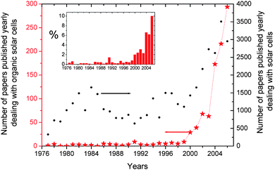 | ||
| Fig. 1 Number of publications dealing with organic solar cells and more generally with solar cells within the period 1976–2006. The inset displays the percentage of publications addressing organic solar cellsversus the overall solar cells publications (Source Scopus). | ||
The global solar electricity market became a $12 billion/year business in 2006, and the PV industry has been growing at an average pace more than 40% per annum over the last ten years.8Fig. 2 shows the expansion trend of the photovoltaic industry during the last two decades. The PV module production has grown exponentially to reach a volume of 2500 MWp in 2006.8 This value is the equivalent of two state-of-the-art Generation III nuclear reactors. Currently, the cumulative world PV installed capacity approach the 7 GWp range.8
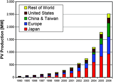 | ||
| Fig. 2 World photovoltaic cell/module production from 1990 to 2006.8 | ||
Nowadays, about 90% of the worldwide solar cell production uses wafer-based crystalline silicon technology. However, the thin film approach is gaining attention, and is likely to represent about 10% of the overall production by 2010.8 Organic solar cells (OSC) are photovoltaic devices based on organic semiconductors (OPV). Although they are still in the development phase, they appear as a likely candidate for large scale PV production. Indeed, OSCs are particularly attractive because of their ease of processing, mechanical flexibility and potential for low cost fabrication of large areas.9 Additionally, their material properties can be infinitely tailored by modifying their chemical structure,10 resulting in greater customization than traditional solar cells allow.
The same analysis performed above for traditional PV can be carried out for OSC (Fig. 1). It reveals that although OSC research was marginal before 1999, it is currently experiencing an exponential growth. Over the last eight years, the number of papers directly addressing OSC has increased by about 65% per annum that is almost twice the breathtaking evolutionary pace of the world photovoltaic market.8 Consequently, in 2006 10% of the scientific publications dealing with photovoltaics focused on OSC.
These impressive figures suggest that the science surrounding the topic of OSC has been evolving greatly during the last years. While the best efficiency reported eight years ago barely reached values higher than 1%, several teams have recently realized devices showing efficiency beyond 5%.11–13 Though impressive, this value is not high enough to allow direct competition against mature PV technologies. Thus, the development of more efficient devices is required to ensure a bright industrial future for OPV. In this regard, the recent realization of tandem solar cells may pave the way toward high performance OSC.
In this article we aim to review the most important and recent developments that have been reported on organic tandem solar cells. In the first part, we introduce some brief theoretical considerations addressing the potential of single and tandem solar cells. Then, we present and discuss the main experimental achievements reported in the literature so far. Finally, we propose some design rules for efficient material combinations in bulk-heterojunction (BHJ) organic tandem solar cells.
2. Theoretical considerations
2.1 Single junction solar cells
In 1961, Shockley and Queisser derived a simple calculation in order to evaluate the thermodynamical limitation of the energy conversion efficiency of a solar cell.14 The two basic phenomena taken into account are schematically represented in Fig. 3a and described below: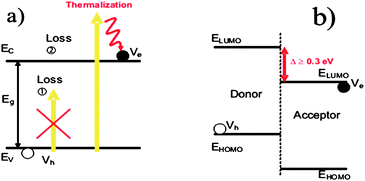 | ||
| Fig. 3 (a) Description of the absorption and thermalization losses occurring in a solar cell. (b) Band diagram representation of a Donor–Acceptor organic solar cell. | ||
• Only photons having an energy larger than the band gap of the photoactive materials can be absorbed and contribute to the photovoltaic conversion.
• Hot charge carriers created upon photon absorption relax down to the conduction band of the photoactive materials, giving rise to the so-called “thermalization”.
The direct consequence of these two assumptions is that the maximum charge extraction potential at open circuit (VOC) is given by the band gap of the photoactive material. Assuming an ideal fill factor (FF) of 1, one can calculate the maximum efficiency η achievable with a material having a band gap energy EG by:
| η(EG) = JSC(EG) × VOC(EG) × FF | (1) |
 | (2) |
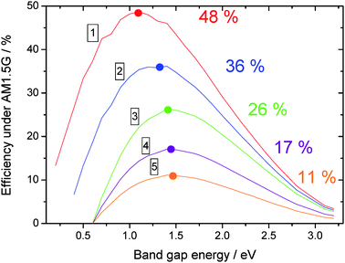 | ||
| Fig. 4 Efficiency vs band gap energy of the photoactive material, for various loss mechanisms. | ||
2.2 The specific case of organic solar cells
As already described extensively in the literature,16 typical organic solar cells are based on a charge transfer occurring at the interface between two distinct materials named Donor and Acceptor, respectively (See Fig. 3b). To allow the separation of the excitons diffusing to this interface, the energy difference between the lower unoccupied molecular orbital (LUMO) levels of the two materials has to be larger than the exciton binding energy. It is shown experimentally that 0.3 eV is a minimum value below which the charge transfer may not occur. Assuming a 0.3 eV loss in the VOC of the device, the maximum efficiency achievable by an organic solar cell is reduced to 36% (case 2 on Fig. 4). For this calculation and all the following, we have assumed that only the Donor material absorbs the light.A detailed screening of the literature reveals that most of the time the VOC observed in a device is not exactly given by the energy difference between the Highest Occupied Molecular Orbital (HOMO) of the Donor and the LUMO of the Acceptor. Indeed, an additional loss of 0.3 eV is often reported, in such a way that the VOC obeys the following empirical equation:17
 | (3) |
This loss, whose origin is still under debate,18 reduces further the maximum energy conversion efficiency of the device down to 26% (case 3 in Fig. 4). Finally, by assuming some charge carrier transport losses (FF = 65%, case 4 in Fig. 4), and some EQE restriction (EQE = 65%, case 5 in Fig. 4), one ends up in a practical efficiency of nearly 11% which should be achievable with today's materials. This efficiency is expected for a Donor having an ideal band gap energy of 1.5 eV and an ideal LUMO difference of 0.3 eV.
Fig. 5 displays the efficiency of an organic solar cell versus the band gap energy of the Donor and the offset between the LUMO of the Donor and the LUMO of the Acceptor, assuming that the VOC follows equation 3.17
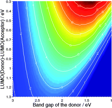 | ||
| Fig. 5 Efficiency of a Donor–Acceptor organic solar cellvs the band gap energy of the Donor, and the LUMO offset between the two materials.17 | ||
It is interesting to note here that the efficiency of the device follows in a monotone way the LUMO offset: The larger the offset, the lower the efficiency. However, the efficiency shows a maximum versus the band gap energy, and this for all LUMO offsets. In this respect, one can conclude that the choice of the Donor–Acceptor couple is as important as the band gap of the absorbing material.
2.3 Tandem solar cells
As explained at the beginning of this article, the two major losses occurring in solar cells are the sub-band gap transmission and the thermalization of hot charge carriers.19 One way to circumvent both effects simultaneously is the realization of a tandem solar cell.The fundamental (detailed balance) limit of the performance of tandem structures has been studied extensively by De Vos.20 This author demonstrated that stacking several sub-cells in series allows theoretical efficiencies ways beyond the Shockley–Queisser limitation, mostly due to an enhancement of the electrochemical potential of charge carrier extraction. While the maximum efficiency of a single cell under non-concentrated sunlight is calculated to be around 30%, this value is raised to 42% for a tandem comprising two sub-cells having a band gap of 1.9 and 1.0 eV respectively, and to 49% for a tandem comprising 3 sub-cells having a band gap of 2.3, 1.4 and 0.8 eV respectively (Table 1). Under the highest possible light concentration, these efficiencies are 40% (one cell), 55% (two cells) and 63% (three cells). This model also predicted the ideal efficiency of a stack with an infinite number of solar cells: Such a tandem system could convert 68% of the non-concentrated sunlight, and 86% of the concentrated sunlight. Experimentally, efficiencies as high as 33.8% have been recently measured on a device based on GaInP/GaInAs/GaInAs under AM1.5G.21
| n | η(%) | E G1/eV | E G2/eV | E G3/eV | E G4/eV |
|---|---|---|---|---|---|
| 1 | 30 | 1.3 | — | — | — |
| 2 | 42 | 1.9 | 1.0 | — | — |
| 3 | 49 | 2.3 | 1.4 | 0.8 | — |
| 4 | 53 | 2.6 | 1.8 | 1.2 | 0.8 |
In the specific case of organic solar cells, the tandem approach allows to tackle two additional issues intrinsic to π conjugated organic molecules. The first one is the quite poor charge carrier mobility and lifetime that limits the distance over which the carriers can be transported.22 This hinders the realization of a thick active layer that would absorb a maximum of light. The second relates to the very nature of light absorption in those molecular materials. Indeed, the absorption spectrum of such materials is not made of a continuum like it is in inorganic semiconductors. It rather shows narrow and discrete peaks as illustrated in Fig. 6.23 Hence a combination of various different materials can help to cover more efficiently the emission spectrum of the sun.
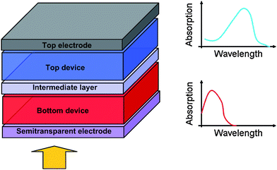 | ||
| Fig. 6 Schematic representation of an organic tandem device comprised of two sub-cells having different, complementary absorption spectra. | ||
Fig. 6 depicts a typical organic tandem cell comprised of two distinct devices stacked on top of each other, each of them being based on a Donor–Acceptor composite. The light which is not absorbed in the bottom device can further impinge on the top cell. Moreover, the thermalization losses are lowered due to the usage of materials having different band gaps. The two cells involved in the device can be connected either in series (two-terminal) or in parallel (three-terminal) depending on the nature of the intermediate layer and on the way the intermediate layer and the two electrodes are connected. In the vast majority of reports though, the series connection is used. In this case, the energetic diagram of the device can be represented as in Fig. 7. The bottom sub-cell comprises a donor and an acceptor that are either stacked on each other or mixed. The intermediate layer should ensure the alignment of the quasi-Fermi level of the acceptor of the bottom cell with the quasi-Fermi level of the donor of the top cell (or vice-versa in a reversed architecture). In other words, the intermediate layer should allow the recombination of holes coming from one sub-cell with electrons coming from the other. Following the same principle, an infinite number of devices can be theoretically piled up this way.
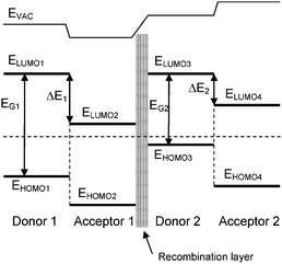 | ||
| Fig. 7 Simplified band diagram of a tandem cell made of two sub-cells connected in series via a recombination layer. | ||
According to Kirchhoff's law, this type of connection implies that the voltage across the whole device is equal to the sum of the voltage across each sub-device. In other words, at open circuit voltage, we have in the case of a loss-free connection:
| VOC1 + VOC2 + VOC3… = VOCtandem | (4) |
However, contrarily to what is often believed, the short circuit current of the tandem cells is not equal to the smallest short circuit current of the sub-cells. It entirely depends on the fill factor (FF) of the respective devices. For illustration, two exaggerated cases are presented in Fig. 8. Fig. 8a shows the combination of a device with lower JSC and significantly higher FF and a device with higher JSC and extremely low FF. According to Kirchhoff's law, a J–V characteristic of the tandem cell with a JSC = Min(JSC1,JSC2) is achieved. In contrast, in Fig. 8b the combination of a device with extremely low FF and lower JSC and a device with very good FF and higher JSC are illustrated. This combination leads to a tandem device with a JSC = Max(JSC1,JSC2). For a description of various cases, the reader is invited to consult Ref. 24.
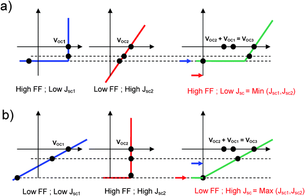 | ||
| Fig. 8 (a) The combination of a device with lower JSC and significantly higher FF and a device with higher JSC and extremely low FF results in a tandem cell with a JSC = Min(JSC1,JSC2). (b) The combination of a device with extremely low FF and lower JSC and a device with very good FF and higher JSC leads to a tandem device with a JSC = Max(JSC1,JSC2). | ||
In order to quantify the highest efficiency realistically achievable with an organic tandem cell and the properties of the donor materials required for this goal, we have introduced a model assuming a series connection of two Donor–Acceptor solar cells stacked via an ideal intermediate layer.25 We have fixed the LUMO offset between both Donor–Acceptor couples to be equal to 0.3 eV, which is the optimum value for bulk-heterojunction composites. We have then varied the band gaps of both donors, assuming the FF of both sub-cells to be 0.65, a rectangular shaped external quantum efficiency of both sub-cells to be 65%, and the internal quantum efficiency of the bottom cell to be 85%. Fig. 9 shows the tandem efficiency isolines. This calculation reveals that, under the given assumptions, the most efficient tandem cells require materials with band gap energy different by about 0.3 eV. Interestingly, a maximum value of almost 15% is achievable, which is about 4% better than the maximum efficiency forecasted for single devices based on a donor with EG = 1.6 eV. This performance can be achieved by using a bottom donor having a band gap of 1.6 eV with a top donor having a band gap of 1.3 eV.
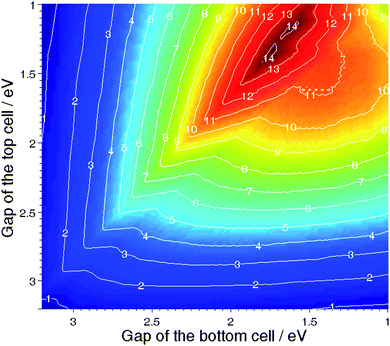 | ||
| Fig. 9 Efficiency of a Donor–Acceptor tandem organic solar cell made of two sub-cells stacked in series vs the band gap energy of the top and bottom Donors; both top and bottom Donor–Acceptor couples are assumed to have a LUMO offset of 0.3 eV. | ||
3. Review of experimental results
Over the last 18 years, an increasing number of scientific reports have been published dealing with stacked or tandem organic solar cells. Several approaches have been employed, depending on the materials used for the active layer and the separation or recombination layer(s). They can be divided in three main categories:(i) Tandem organic solar cells where both the bottom (in front of the light illumination) and the top (back) cells are based on low-molecular-weight evaporated molecules.
(ii) Hybrid tandem organic solar cells in which one of the cells, either bottom or top cell, is processed from solution while the other cell is based on vacuum-deposited low-molecular-weight materials.
(iii) Fully solution-processed tandem organic solar cells where both the bottom and top cells are processed from solution.
Besides the nature of the active layer, an important characteristic of the tandem device resides in the type of intermediate layer employed. As explained above, these intermediate layers are used as a recombination center ensuring the alignment of the quasi-Fermi levels of the sub-cells stacked in series. Moreover, they can act as a protective layer to support the bottom cell during the top active layer deposition. In the earliest reports, this intermediate layer was often based on a thin, vacuum processed metallic layer. But recently, an increasing number of organic tandem solar cells with fully solution-processed interlayers are reported.
In this section, the different types of organic tandem and multijunction photovoltaic cells are described and recent results obtained by various groups are reviewed.
3.1 Evaporated small molecule based tandem organic solar cells
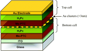 | ||
| Fig. 10 Schematic structure of the first tandem organic solar cell realized by Hiramoto et al.26 | ||
Around 10 years later, Forrest and his group followed the same approach, and yet another kind of small molecule material was utilized as the active layer. In 2002, Yakimov and Forrest27 demonstrated high VOC organic photovoltaic cells that incorporated two, three, or five stacked thin heterojunctions consisting of Cu–phthalocyanine (CuPc) as a donor and 3,4,9,10-perylenetetracarboxylic bis-benzimidazole (PTCBI) as an acceptor. In this case, an ultrathin (≈5Å) discontinuous layer of Ag clusters served as the charge recombination sites. The sequence of donor to acceptor to metal, repeated two, three and five times, resulted in dual, triple, and fivefold heterojunction PV cells. The power conversion efficiencies (η) of the two and three HJ cells under one sun (AM1.5 illumination) were η = 2.5% and 2.3%, with VOC = 0.93 and 1.2 V, respectively. These values of η were more than twice that of a comparable single junction cell based on the same materials, where η = 1.1%. On the other hand the five HJ devices showed significantly lower efficiency (∼1%) than the one of the devices comprising two or three HJs. This observation suggests that the principal limitation of their multiple HJ architecture is the reduction in light absorption by each individual stacked cell. Indeed, in order to maintain a balanced current between all sub-cells, each of them has to be made fairly thin. The stacking of sub-cells with complementary absorption profiles over the visible spectrum, do solve this problem as will be discussed later. Moreover, Peumans and et al.28 have indicated that the highest power conversion efficiency achieved in this type of tandem device was approximately 40% higher than the one predicted. This difference was attributed to an optical field enhancement due to Mie resonance29 and scattering of photons by the Ag nanoclusters used in the intermediate layer. This important effect was further investigated by Rand, Peumans and Forrest in 2004.30 These authors showed that plasmonic effects could be beneficial for some materials such as CuPc and PTCBI, where the small diffusion length (LD) of excitons requires the use of thin active layers. In this case, the Donor–Acceptor interfaces extend within the intensity enhancement zone (shaded region in Fig. 11). For materials with large LD (for instance C60) though, the potential efficiency improvements afforded by this mechanism are limited.
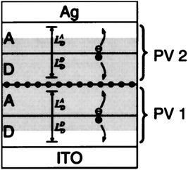 | ||
| Fig. 11 Schematic structure of a cross section of a tandem organic photovoltaic cell. The enhancement distance (shaded region) and exciton diffusion lengths LDD and LAD of the donor (D) layer and acceptor (A) layer of each device (PV1 and PV2) are labeled. Ag clusters are shown as ●. The schematic shows a representation of current generation in the tandem cell, where dissociation of excitons at the D–A interface leads to a hole in PV1 and electron in PV2 which contribute to photocurrent. The excess electron in PV1 and hole in PV2 recombine at the Ag cluster layer to prevent cell charging.30 | ||
Later, Xue et al. achieved a significant improvement in efficiency31 by stacking two bulk-heterojunctions32 made of co-evaporated CuPc and C60. Optimizing the optical absorption in each active layer allowed them to report an efficiency of up to 5.7%, that was about 24% more efficient than the single CuPc/C60 devices. Thin layers of PTCBI and bathocuproine (BCP) were employed as “exciton blocking layer” in the front (adjacent to the ITO) and back (adjacent to the top electrode) sub-cells respectively, thereby forming a highly efficient double bulk-heterojunction structure with a FF as high as 0.59. It was proposed as well that the blocking layer could protect the active layer from hot metallic particles during the thermal evaporation process. In this tandem stack, the recombination centers were Ag nanoclusters with 5 Å average thickness buried in a 50 Å thick 4, 4′, 4″-tris(3-methyl-phenyl-phenyl-amino)triphenylamine (m-MTDATA) p-doped with 5 mol% tetrafluoro-tetracyano-quinodimethane. The interpenetrated CuPc/C60 layer is sandwiched between homogeneous donor and acceptor layers, called a “hybrid planar-mixed heterojunction” (PM–HJ). The structure of the CuPc/C60 hybrid PM–HJ tandem cell is schematically shown in Fig. 12. The thicknesses of the different layers of the bottom and top cells that led to an efficiency higher than 5% are summarized in Table 2. It suggests the importance of layer thickness optimization to achieve maximized efficiency in the tandem structure.
| Cell label | Front cell | Front cell | Front cell | Front cell | Back cell | Back cell | Back cell | Back cell | η (%) |
|---|---|---|---|---|---|---|---|---|---|
| CuPc | CuPc/C60 | C60 | PTCBI | CuPc | CuPc/C60 | C60 | BCP | ||
| A | 100 | 180 | 20 | 50 | 20 | 130 | 250 | 75 | 5.4 |
| B | 75 | 125 | 80 | 50 | 60 | 130 | 160 | 75 | 5.7 |
| C | 90 | 110 | 0 | 50 | 50 | 100 | 210 | 100 | 5.0 |
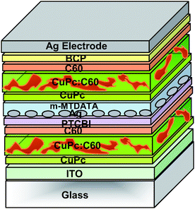 | ||
| Fig. 12 Schematic structure of the tandem organic solar cell realized by Xue et al.31 formed by stacking two hybrid PM-HJ cells in series. | ||
The evaporated small molecule route was investigated as well by Maennig et al.33 They introduced a p–i–n type heterojunction architecture for organic solar cell where the active region is sandwiched between two wide band gap layers. Within the numerous different n- and p-type materials that were tried, it appeared that the p-type N,N,N′,N′-tetrakis(4-methoxyphenyl)-benzidine (p-doped MeO–TPD) and the n-type C60 layers were the best choices: In combination with ZnPc/C60 (as the i-type materials), they led to an efficiency close to 2% in single cells, with an internal quantum efficiency (IQE) up to 82%. The main advantages of using wide-gap materials at the interface are the following:
• They induce a contact selectivity for the electrons and holes and thereby act as membranes allowing only the ‘right’ type of charge carrier to leave the photoactive layer at a given interface.
• The thickness of the active layer can be varied at will without limitations due to short circuits that may occur between successive conducting layer.
• They permit a certain degree of freedom to optimize the cells in terms optics:34 n- and p-type layers can act as a optical spacer35 and tuning their respective thickness can allow to optimize the electromagnetic field in the active layers.
Thus, stacking p–i–n cells as a building block for tandem devices allows to benefit from the same advantages. It is mentionable that first two benefits are provided by the exciton blocking layers in the Xue structure as well (Fig. 12).
In the Yakimov and Forrest approach, it can be hardly avoided that metallic recombination centers for the charge carriers act as recombination centers for excitons as well while with the wide band gap approach, the recombination zone between the individual cells is placed between wide-gap transport layers so that they are hidden from the excitons in the active layers.
Fig. 13 depicts the device structure for two stacked p–i–n cells. Between individual cells an ultrathin gold layer is introduced. In fact, in this simple design called “a p–i–n cell with an electron-to-hole conversion contact”, the metal rather formed clusters and improves interface recombination and generation dynamics at reverse and forward bias voltage, respectively. The authors believe that the gold interlayer may play a dual role here. First, it is expected to hinder interdiffusion of dopants that otherwise lead to a depletion region in cells without metal interlayer. Second, it provides gap states that assist tunneling through the p–n junction barrier. Therefore, they conclude that the function of the metal interlayer is somewhat different from those used in stacked undoped heterojunction cells. As expected, the tandem cell showed an almost doubled VOC up to 0.85 V and significantly higher power efficiency of 2.4% compared to the 1.95% efficient single p–i–n cell (around 23% improvement).
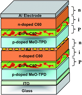 | ||
| Fig. 13 Schematic structure of the tandem organic solar cell realized by Maennig et al.33 based on multiple stacked p–i–n structures, each of them comprising a photovoltaic layer sandwiched between p- and n-type wide-gap transport layers. | ||
Later, Drechsel et al.36 achieved further improvements by finding the appropriate dopants for both the p- and n-type wide-gap transport layers. They stacked two p–i–n cells both based on a phthalocyanine–fullerene blend, as photoactive layer, reaching efficiencies up to 3.8% as compared to 2.1% for the respective single p–i–n cell. The hole transporting material MeO–TPD was doped by the strong electron acceptor tetrafluorotetracyano–quinodimethane.37 The n-type doping of the electron transporting C60 matrix was achieved with cationic dyes, such as Rhodamine B or their leuko base (leuko crystal violet) as a precursor.38
Triyana et al.39 tried to optimize a tandem triple-heterojunction based on two kinds of phthalocyanine derivatives as donors (CuPc and H2Pc), and three perylene derivatives as acceptors, namely 3,4,9,10-perylenetetracarboxylic bis-benzimidazole (PTCBI), 3,4,9,10-perylenetetracarboxycilic diimide (PTCDI) and 3,4,9,10-perylenetetracarboxylic dianhydride (PTCDA). The various sub-cells were stacked via an ultrathin (≈0.7 nm) metal layer.40 Despite large efforts to optimize the respective thicknesses of the numerous layers involved in the devices, the authors could not achieve efficiency higher than 1.4%. However, they proposed an interesting concept based on a multistep charge separation. According to them, stacking PTCDI directly onto PTCBI would allow electrons photo-generated in the PTCDI film to move quickly into the PTCBI layer along the downward potential. Thus, the electrons in the PTCBI layer are prevented from back electron transfer into the PTCDI layer due to the potential barrier, and the recombination of the photo-generated carriers in the vicinity on donor–acceptor interface is effectively suppressed.
A brief summary of the reports dealing with evaporated small molecules tandem organic solar cells is presented in Table 3. Fig. 14 depicts the chemical structures of the most commonly utilized materials in those tandem devices.
| Year | Intermediate layer | Bottom cell and top cell | Tandem cell | Ref. | |||||||
|---|---|---|---|---|---|---|---|---|---|---|---|
| Active Materials | V OC/V | FF | J SC/mA cm−2 (mW cm−2) | Eff (%) | V OC/V | FF | J SC/mA cm−2 (mW cm−2) | Eff (%) | |||
| 1990 | 2 nm Au | H2Pc/Me–PTC | 0.44 | — | 2.7 (78) | — | 0.78 | — | 0.9 (78) | — | 26 |
| 2002 | 0.5 nm Ag | CuPc/PTCB | 0.45 | — | — | 1.0 | 0.9 | 0.43 | 6.5 (100) | 2.6 | 27 |
| 2004 | 0.5 nm Ag | CuPc/C60 | — | 0.64 | — | 4.6 | 1.03 | 0.59 | 9.7 (100) | 5.7 | 31 |
| 2004 | 20 nm n-doped C60 + 0.8 nm Au + 30 nm p-doped Meo–TPD | ZnPc/C60 | 0.45 | 0.39 | 13.9 (125) | 1.95 | 0.85 | 0.53 | 6.6 (125) | 2.4 | 33 |
| 2005 | 0.8 nm Au | ZnPc/C60 | 0.5 | 0.37 | 15.2 (130) | 2.1 | 0.99 | 0.47 | 10.8 (130) | 3.8 | 36 |
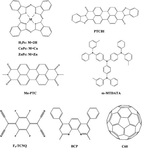 | ||
| Fig. 14 The chemical structure of the most utilized materials in evaporated small molecule based tandem organic solar cells. | ||
3.2 Hybrid and fully solution-processed tandem organic solar cells
In order to produce organic tandem solar cells employing solution processing, serious engineering challenges have to be met. Multiple layers have to be cast on top of each other, and because casting a further layer from solution dissolves the underneath layer it is something that has to be avoided. Researchers have developed several approaches to circumvent this intrinsic problem. These comprise employing sophisticated material sequences soluble in incompatible solvents or applying one or more layers by vacuum deposition methods.In the case of the solution-processed organic solar cells, the first tandem structures were reported by Kawano et al. in 200641 based on conjugated poly[2-methoxy-5-(3′,7′-dimethyloctyloxy)-1,4-phenylene vinylene] (MDMO–PPV) blended with the fullerene derivative PCBM as the active layer for both top and bottom cells. The 80 nm thick active layers of MDMO–PPV/PCBM were spin-coated in dry Ar atmosphere whereas the 20 nm thick ITO interlayer was deposited by DC magnetron sputtering in relatively high pressure of 1 Pa of Ar without damaging the underneath active layer and substrate heating. The single reference BHJ organic solar cell yielded a VOC of 0.84 V and a JSC of 4.6 mA cm−2, together with a FF of 0.59, the efficiency was calculated to be 2.3%. On the other hand the characteristics of the stacked cell were VOC = 1.34 V, JSC = 4.1 mA cm−2, FF = 0.56 and η = 3.1%. Stacking two devices based on the same material combination led to 35% performance improvement compared to the single one.
The VOC of the stacked BHJ cells fabricated by the spin-coating method were 1.6 times as large as that of the single reference cell, unlike the small molecule HJ-organic solar cells, where stacking results in doubling of the VOC. The loss is attributed to the high work function of ITO (approximately 4.9 eV). The inserted ITO hence is a non-ohmic electron contact to the organic layer, thus reducing VOC. Indeed, the value of the VOC of the stacked cell is in good agreement with the sum of that of the bottom reference cell: glass/ITO/PEDOT:PSS/MDMO:PPV/PCBM/ITO (VOC = 0.48 ± 0.04 V) and the top reference cell: glass/ITO/PEDOT:PSS/MDMO-PPV:PCBM/Al (VOC = 0.73 ± 0.01 V). This work indicates that in order to achieve highly efficient stacked BHJ cells, the interlayer is required to meet several demands: structural continuity as well as chemical and mechanical stability in the coating process. In order to minimize losses in VOC and hence efficiency, proper energy level alignment is a must.
In all systems where the bottom and the top cell are based on the same combination of active materials, an improvement in performance is more related to overcoming transport limitations in the single junction cells rather than reducing thermalization losses and increasing spectral coverage.25 The same year, Dennler et al.42 reported the first real organic tandem cell comprising two sub-cells with different active materials and different absorption spectra. The authors stacked a ZnPc/C60 based cell on top of a P3HT/PCBM interdiffused bilayer using a 1nm thick Au intermediate recombination layer (Fig. 15). In this case maximization of the VOC of the device was done by spin-coating a pure C60 layer onto the interdiffused P3HT/PCBM bilayer (as suggested before by Chen et al.43) and by evaporating pure ZnPc prior to the ZnPc/C60 blend. They measured a JSC of 8.5 mA cm−2, a VOC of 0.55 V and a FF of 0.55, yielding a η of 2.6% for the single P3HT:PCBM reference cell. In the case of the small molecule based cell, a JSC of 9.3 mA cm−2, a VOC of 0.47 V and a FF of 0.5 were recorded, yielding an efficiency of about 2.2%. Thus, the fact that the tandem cell showed a VOC of 1.02 V, equal to the sum of the individual VOC's of the sub-cells, suggests that an efficient series connection between the sub-cells was achieved. The FF of the tandem cell was found to be about 0.45 and the tandem device showed a quite reduced JSC of 4.8 mA cm−2, which resulted in an efficiency of 2.3%. Since no effort was done on thickness optimization, the limitation of the tandem cell performance could be mostly due to a lack of optimization of the respective thicknesses of the sub-cells. Spectral photocurrent measurements with two light sources showed that the photon harvesting in this tandem cell occurs over the entire visible range from 400 to beyond 800 nm.
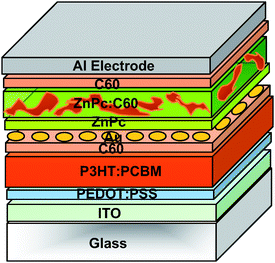 | ||
| Fig. 15 Schematic structure of the tandem organic solar cell realized by Dennler et al.42 comprising of two sub-cells with complementary absorption spectra. | ||
Further reports followed up this hybrid solution-processed approach yet with another Pc, namely CuPc.44 For instance, Colsman et al. reported in 200644(a) a similar approach, where C60 and ZnPc were substituted by lithium doped 4,7-diphenyl-1,10-phenanthroline (Bphen:Li) and (2,5-cyclohexadine-1,4-diylidene)-dimalononitrile doped 4,4′,4″-tris(N-3-methylphenyl-N-phenyl-amino)-tiphenylamine (MTDATA:F4TCNQ), respectively as the transport layers. The bottom single cell based on the 60 nm thick P3HT:PCBM blend led to 1.5% efficiency and top cell based on the 40 nm thick CuPc/C60 bilayer yielded an efficiency of 1.1%, resulting in an overall tandem efficiency of 1.2%. Janssen et al.44(b) applied thermally evaporated oxides such as WO3 with a work function similar to that of gold as transparent interlayer and part in the connecting architecture of the stacked hybrid organic PV cells. They demonstrated that compared to the established concept using an Au interlayer, efficiency of the tandem cells with a WO3 interlayer were significantly improved. For an optimum thickness of the small molecule CuPc/C60 sub-cell at 60 nm and an optimum thickness of the P3HT:PCBM layer at 200 nm for the polymer sub-cell, an efficiency up to 1.5% and 1.6% (at 160 mW cm−2) were obtained. Finally, the resulting tandem cells with a sequence of LiF (0.5 nm), Al (1 nm), and WO3 (3 nm) as interlayer exhibited efficiency of 3% at 160 mW cm−2. Interestingly, they reported a strong light intensity dependence. The tandem cell achieved at 16 mW cm−2 up to 4.6% which is considerably higher than 3% efficiency at 160 mW cm−2. This effect can be attributed to reduced photocurrent under the lower light intensities, hence the limitation due to the high series resistance of the intermediate layer is less pronounced.
The first tandem cell composed of two solution-processed sub-cells based on two different conjugated polymers was reported by Hadipour et al. in 2006.45 They were able to couple a wide band gap polymer with a low band gap polymer. The combination of a 110 nm poly(2,7-(9,9-dioctyl)fluorene)-alt-5,5-(4′,7′-di-2-thienyl- 2′,1′,3′-benzothiadiazole) (PFDTBT) : PCBM (1 : 4) layer for the bottom cell (large band gap) and a 90 nm poly(5,7-di-2-thienyl-2,3-bis(3,5-di(2-ethylexyloxy)phenyl)-thieno(3,4-b)pyrazine) (PTBEHT) : PCBM (1 : 4) layer for the top cell generated a broad spectral coverage. Since a gold middle electrode does not give an ohmic contact for electrons, a very thin layer of 0.5 nm LiF and 0.5 nm Al is added on top of the bottom active layer. LiF/Al provides an ohmic contact to PCBM while 60 nm spin-coated PEDOT:PSS layer on top of the Au layer provides the ohmic contact to the polymer of the top cell. In this case, the gold layer has to protect the LiF/Al cathode of the bottom cell from being dissolved and oxidized during the spin-coating of the water based PEDOT:PSS. So, a continuous 10–50 nm Au layer was deposited on top of the bottom cell. They demonstrated that such a weakly transparent electrode acts as a charge recombination center, a protection layer for the first cell during spin-coating of the second cell and as an optical cavity as well. A high VOC of 1.4 V was achieved which was the sum of VOC for the bottom cell (0.9 V) and the top cell (0.5 V). The performance of the tandem cell was 0.57% which is 1.6 times higher than the performance of the bottom cell (0.35%) and 2.5 times higher than the performance of the top cell (0.23%), resulting at least 62% improvement compared to the more efficient single cell.
So far, hybrid or solution-processed organic tandem cells with an evaporated or sputtered intermediate layers have been reviewed. The significant innovation of the work of Gilot et al. relied on the intermediate layer, which was for the first time entirely processed from solution alike the whole tandem device.46 The authors used a layer of zinc oxide nanoparticles47 and a layer of PEDOT as the recombination center. Importantly, they established a solvent combination that allows subsequent layers to be processed without affecting previously deposited layers. The blends of MDMO–PPV:PCBM and P3HT:PCBM were spin coated from chlorobenzene as the bottom and top active layers, respectively. The ZnO nanoparticles were dispersed in acetone and spin coated (≈30nm) prior to the deposition of a PH neutral PEDOT dispersion. The ZnO/PEDOT intermediate layer did not disturb the underlying MDMO–PPV layer and also protected it from damage during the next solution-processed layer deposition. A good contact between ZnO and PEDOT is needed to prevent a voltage drop across the interface and so allows the holes and the electrons to recombine efficiently. Doping strategies have been applied. For the intermediate layers in this study: PEDOT was heavily p-doped and the ZnO layer could easily be doped by exposure to UV irradiation (photo-doping) for a few seconds.48 A VOC of 1.53 V and 2.19 V were achieved for a tandem and a triple junction solar cell, respectively; corresponding closely to the sum of the VOC of single cells. This successful deposition of fully solution-processed multijunction organic solar cells opened up the possibility for roll-to-roll production of tandem cells.
The breakthrough in solution-processed tandem cells was reported by Kim et al., demonstrating a high efficiency tandem device showing a 38% performance improvement versus the best single device.49 These tandem devices were entirely solution-processed except for the top evaporated electrode. For the bottom BHJ cell a 130 nm thick layer of poly[2,6-(4,4-bis-(2-ethylhexyl)-4H-cyclopenta[2,1-b;3,4-b′]dithiophene)-alt-4,7-(2,1,3-benzothiadiazole)] (PCPDTBT) : PCBM (1 : 3.6) from chlorobenzene was used and the top cell was made of a blend of P3HT : PC70BM (1 : 0.7) processed from chloroform with a thickness of 170 nm. The absorption bands of PCPDTBT and P3HT compliment each other and these two materials cover the spectral region from 400 to nearly 900 nm. It is worth mentioning that the selective usage of PCBM or PC70BM allows the reduction of spectral overlap in the two BHJ blends and thereby ensures an optimized JSC.50 The authors have chosen an “inverted tandem cell” structure with the low band gap BHJ composite (PCPDTBT:PCBM) as the bottom cell and the higher band gap BHJ composite (P3HT:PC70BM) as the top cell and found a higher performance for this layer sequence than for the usual sequence. The two polymer–fullerene layers were separated by a transparent TiOx layer and a highly conductive PEDOT:PSS layer. The TiOx layer was deposited by means of sol–gel chemistry51 and served as the electron transport and collecting layer of the first cell. The usage of sol–gel TiOx turned out advantageous because of its mechanical stability, which enables the fabrication of the second cell without damaging the bottom cell. The maximum efficiency reported so far of any organic tandem solar cell up to 6.5% was achieved in this study at an illumination of 100 mW cm−2 based on a 3% efficient bottom and a 4.7% efficient top cell. Table 4 represents a list of these all-solution-processed tandem cells illuminated under different light intensities.
| Light intensity/mW cm−2 | V OC/V | J SC/mA cm−2 | FF | η (%) |
|---|---|---|---|---|
| 20 | 1.15 | 2.4 | 0.68 | 6.7 |
| 50 | 1.2 | 4.1 | 0.67 | 6.6 |
| 100 | 1.24 | 7.8 | 0.67 | 6.5 |
| 200 | 1.28 | 15 | 0.63 | 6.1 |
A brief summary dealing with partially or fully solution-processed tandem organic solar cell is represented in Table 5.
| Year | Intermediate layer | Bottom cell | Top cell | Tandem cell | Ref. | |||||||||||
|---|---|---|---|---|---|---|---|---|---|---|---|---|---|---|---|---|
| Active Materials | V OC/V | FF | J SC/mA cm−2 (mW cm−2) | Eff (%) | Active Materials | V OC/ V | FF | J SC/mA cm−2 (mW cm−2 | Eff (%) | V OC/V | FF | J SC/mA cm−2 (mW cm−2) | Eff (%) | |||
| 2006 | 20 nm ITO + PEDOT:PSS | MDMO–PPV:PCBM | 0.84 | 0.58 | 4.6 (100) | 2.3 | as bottom | as bottom | as bottom | as bottom | as bottom | 1.34 | 0.56 | 4.1 (130) | 3.1 | 41 |
| 2006 | 1 nm Au | P3HT: PCBM | 0.55 | 0.55 | 8.5 (100) | 2.6 | ZnPc/C60 | 0.47 | 0.5 | 9.3 (100) | 2.2 | 1.02 | 0.45 | 4.8 (100) | 2.3 | 42 |
| 2006 | 8 nm Bphen:Li +10 nm Au +8 nm MTDATA:F4TCNQ | P3HT: PCBM | 0.57 | 0.65 | 3.4 (100) | 1.5 | CuPc/C60 | 0.51 | 0.44 | 4.9 (100) | 1.1 | 0.99 | 0.47 | 2.5 (100) | 1.2 | 44a |
| 2006 | 0.5 nm LiF +0.5 nm Al +15 nm Au + 60 nm PEDOT:PSS | PFDTBT: PCBM | 0.9 | 0.5 | 1.0 (100) | 0.4 | PTBEHT: PCBM | 0.5 | 0.64 | 0.9 (100) | 0.23 | 1.4 | 0.55 | 0.9 (100) | 0.6 | 45 |
| 2007 | 0.5 nm LiF+ 1 nm Al + 3 nm WO3 | P3HT: PCBM | 0.44 | - | 16.7 (160) | 1.6 | CuPc/C60 | 0.4 | - | 15.4 (160) | 1.5 | 0.6 | - | 17 (160) | 3 | 44b |
| 2007 | 30 nm ZnO + PEDOT | MDMO–PPV:PCBM | 0.82 | 0.55 | 4.1 (100) | 1.9 | P3HT: PCBM | 0.75 | 0.48 | 3.5 (100) | 1.3 | 1.53 | 0.42 | 3.0 (100) | 1.9 | 46 |
| 2007 | 8 nm TiOx + 25 nm PEDOT:PSS | PCPDTBT: PCBM | 0.66 | 0.5 | 9.2 (100) | 3.0 | P3HT: PCBM | 0.63 | 0.69 | 10.8 (100) | 4.7 | 1.24 | 0.67 | 7.8 (100) | 6.5 | 49 |
3.3 Specific approaches to tandem organic solar cells
All the reviewed tandem cells so far are based on two terminal devices, comprising two or more cells connected in series. However several groups have suggested other approaches to realize multijunction devices. This part of the study will discuss some of these novel concepts.Shrotriya and co-workers have reported a stacking method to overcome all processing difficulties. They superimposed two independent devices, and connected them either in series or in parallel.52 To do so, the bottom cell required a semitransparent cathode which was realized with a 1 nm LiF/2 nm Al/12 nm Au layer sequence showing a maximum transparency of almost 75%. Both active layers were made of a blend of poly(2-methoxy-5-(2′-ethyl)hexyloxy)-1,4-phenylenevinylene (MEH–PPV) and PCBM with a layer thickness of about 70 nm. The structure of the device is given in Fig. 16. For the bottom single cell a JSC of 2.6 ± 0.15 mA cm−2, a VOC of 0.86 ± 0.02 V, a FF of 0.45 and a conversion efficiency of 1.1% was achieved. The top cell showed better extraction and higher JSC up to 3.2 ± 0.1 mA cm−2. Connecting them in series led to JSC = 3.4 mA cm−2, VOC = 1.64 V and FF = 0.45 with 2.4% efficiency and for parallel connection; JSC = 6.3 mA cm−2, VOC = 0.84 V and FF = 0.45 with an efficiency of 2.4% surprisingly, in the series connection the tandem JSC is higher than that of the single cells and in the parallel connection tandem JSC is higher than the sum of the single cells JSC. Thus, series and parallel connection gave comparable efficiency.
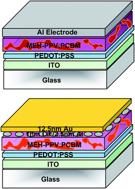 | ||
| Fig. 16 Schematic structure of the tandem organic solar cell realized by Shrotriya et al.52 Two independent devices are superimposed and connected either in series or in parallel by optimizing semitransparent top electrode. The bottom cell has a semitransparent cathode consisting of 1nm LiF / 2 nm Al / 12 nm Au with a maximum transparency of almost 75%. | ||
In 2007 Hadipour et al. introduced an additional solution-processable, transparent, and insulating layer between the bottom and the top sub-cell which serves as an optical spacer and in parallel allows the fabrication of a monolithic four terminal device.53 In this approach, the thickness of the bottom cell is optimized with respect to its electrical performance and the optical output to the top cell is fine tuned by varying the thickness of the optical spacer. As depicted in Fig. 17, the cathode of the bottom cell (120 nm P3HT:PCBM) was evaporated with 3 nm Samarium (Sm) and 12 nm Au. Then 250 nm polytrifluoroethylene (PTrFE), dissolved in methyl ethyl ketone (MEK), was spin coated onto the bottom cell to separate the two sub-cells, as suggested earlier by Persson et al.54 The top cell was made of 90 nm PTBEHT:PCBM on top of a 20 nm Au/50 nm PEDOT:PSS anode. The electrodes of the bottom and the top cell can be connected externally in series or in parallel. They concluded that the most efficient connection for the active materials employed was the parallel one;53 with an VOC of 0.59 V, JSC of 9.2 mA cm−2 and FF of 0.54.
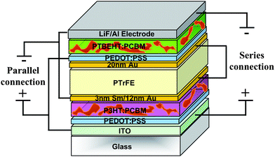 | ||
| Fig. 17 Schematic structure of the tandem organic solar cell realized by Hadipour et al.53 where an additional optical spacer is used to electrically separate the two sub-cells. The two sub-cells can be connected in series or in parallel by external wiring. | ||
Tvingstedt and his colleagues proposed a novel geometrical modification of multijunction cells so called “folded reflective tandem device”.55 The device scheme is depicted in Fig. 18. This geometry enables the construction of tandem or multiple band gap solar cells with arbitrary electrical parallel or series connection. In addition, this geometry allowed the authors to benefit from three major advantages: (i) the reflected light of one cell is directed toward the second one, which ideally has a complementary absorption spectrum; (ii) the folded structures cause light trapping at high angles and absorb more photons from incoming solar light; (iii) the tilting of the cells enhances the light path within the active layer.56 The used polymers were based on alternating fluorine copolymers (APFs) combined with PCBM, APFO3:PCBM for one cell and APFO Green9:PCBM for the other cell. The polymer blends were spin coated to a thickness of 50–60 nm and sandwiched between a transparent ITO/PEDOT:PSS electrode and a LiF/Al metal electrode. The conversion efficiency for a series connection increased from 2% up to 3.7% upon folding the V-shaped device from 0° to 70°. The advantage of this approach is that all the problems related to multijunction stacking, extra transparent electrodes, and solvent incompatibility are simply avoided.
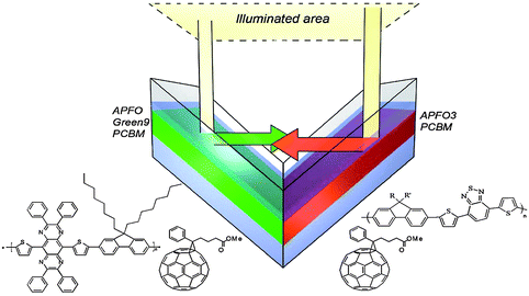 | ||
| Fig. 18 Sketch of the folded tandem cell realized by Tvingstedt et al.55 The chemical structures of the exploited alternating polyfluorenes, namely APFO3, APFO Green-9, and the acceptor molecule PCBM, are also shown. | ||
Zhang et al. demonstrated a simple alternative to a parallel interconnection in 2008.57 In this device structure, a PCBM layer is employed to simultaneously form a bilayer heterojunction PV sub-cell with the underlying CuPc layer and a BHJ photovoltaic sub-cell blended with P3HT. This simple structure shown in Fig. 19a was also proposed four years ago by Maennig et al.33 This structure can be regarded as a parallel connection of two individual sub-cells, as described in the simple circuit model of Fig. 19b. In comparison with the conventional tandem structure, the omission of the semitransparent intercellular connection layer reduces the complexity of the device processing and the light losses. According to the working principle of the bilayer PV cells, only the excitons created in 5–10 nm thick of CuPc can diffuse to the interface of the CuPc/PCBM where they are separated into free carriers. An 8 nm thin CuPc layer was deposited underneath a P3HT:PCBM BHJ layer, and since the HOMO levels of CuPc and P3HT are almost the same, holes were transported through the extra CuPc layer and extracted by the anode. The low conductivity of the CuPc adds a loss mechanism that is depicted as an additional resistor in Fig. 19b. The enhanced JSC = 8.63 mA cm−2 and η = 2.79% of the tandem structure were nearly the sum of those of the stand-alone cells of CuPc/PCBM (JSC = 2.09 mA cm−2 and η = 0.43 %) and 80 nm thick P3HT:PCBM (JSC = 6.87 mA cm−2 and η = 2.5 %).
 | ||
| Fig. 19 (a) Schematic structure of the proposed tandem organic solar cell by Zhang et al.57 In this structure, PCBM is used simultaneously to form the CuPc/PCBM bilayer HJ sub-cell and the P3HT:PCBM BHJ sub-cell. (b) A simple equivalent circuit model of the proposed tandem PV cell. The extra resistor indicates the fact that holes generated in the blend layer have to be transported across the CuPc layer. | ||
The very same approach is followed by Kim et al., CuPc layer is substituted by 40 nm C60 layer on top of the BHJ P3HT:PCBM layer.58 In this study, a poor efficiency (≈0.07 %) was achieved.
Finally, Hagemann et al. have realized a novel concept of thermocleavable materials in an all-solution-processed tandem polymer solar structure.59 In order to gain more flexibility in processing various layers, precursor materials were used that can be converted from a soluble to an insoluble form by an annealing step. A liable bond is chosen as the linker between the groups that convey solubility and the active material backbone. In this study the solubilizing group is a branched alkyl chain attached to the active conjugated polymer backbone through an ester group. When heated this bond breaks, eliminating a volatile alkane and leaving the polymer component insoluble. These authors have used the wide band gap poly-(3-(2-methylhexan-2-yl)-oxycarboxydithiophene (P3MHOCT) blended with zinc oxide nanoparticles as the bottom active layer. When heated to around 200 °C an insoluble poly(3-carboxydithiophene) (P3CT):ZnO is obtained. Similarly, the top active layer is made of a low band gap poly-(3′-(2,5,9)-trimethyldecan-2-yl)-oxycarbonyl-(2,2′;5′,2″)terthiophene-1,5″-diyl)-co-(2,3-diphenylthieno(3,4-b)pyrazine-5,7-diyl)) (P3TMDCTTP) blended with ZnO nanoparticles which is converted to an insoluble P3CTTP:ZnO layer through a short thermal treatment at around 200 °C. A semitransparent intermediate layer comprising PEDOT:PSS and ZnO separates the bottom and top cells from each other. Despite the very poor performance of the tandem device (0.02%), mostly due to poor efficient single cells, it is noticeable that by using this method there is no limit in the choice of solvents when processing the subsequent layers. More research into this new idea appear very worthwhile.
A short overview of the chemical structure of the most prominent materials utilized in partially or fully solution-processed tandem organic solar cells or novel tandem approaches are given in Fig. 20.
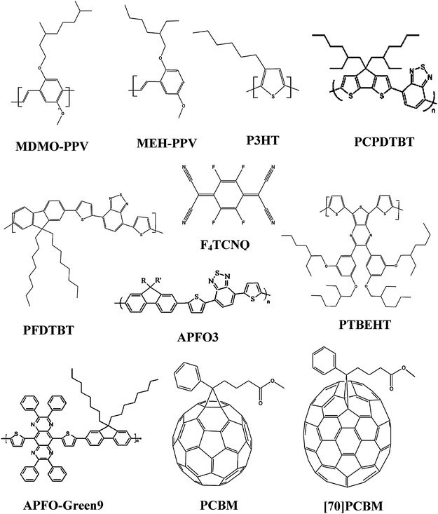 | ||
| Fig. 20 The chemical structure of all the most used materials in partially or fully solution-processed tandem organic solar cells. | ||
Fig. 21 depicts the absolute efficiency and the relative improvement of the most efficient tandem organic solar cells as compared to the maximum efficiency of the single sub-cells during last years. From this diagram, it becomes clear that most efforts in the recent years were concentrated on solution-processed tandem organic solar cells, making a big step towards the roll-to-roll mass-production of organic tandem solar cells.
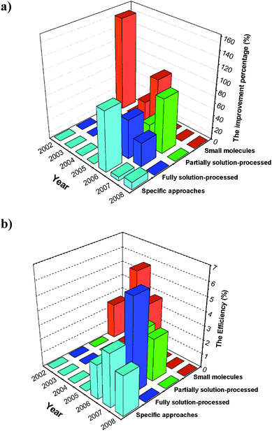 | ||
| Fig. 21 (a) The improvement percentage of the most efficient small molecules evaporated (red), partially solution-processed (green), fully solution-processed (dark blue) and specific (light blue) tandem organic solar cells compared to the maximum efficiency of the single sub-cells and (b) their absolute efficiency during recent years. | ||
4. Design rules for donors in bulk-heterojunction tandem solar cells
A closer look at the published reports on organic tandem solar cells reveal that they do not yet achieve any impressive enhancement compared to that achieved theoretically by efficient single cells. Indeed, none of the results mentioned in Table 3 and 5 show higher efficiencies than what the materials employed could achieve in single devices (see Fig. 5). In order to substantiate this observation, we have introduced a simple model that allows prediction of the efficiency increase that one can expect going from single cells to tandem cells. This model is already described in detail elsewhere,25 and only the main findings will be briefly summarized.We have used the very same approach as Scharber et al.17 (Fig. 5), adapted to a tandem cell comprising two sub-cells made of a mixture of a donor (1 and 2, respectively) and PCBM. An ideal intermediate layer placed between the sub-cells is assumed to ensure perfect alignment of the quasi-Fermi level of PCBM of the bottom cell with the quasi-Fermi level of the donor in the top cell. The VOC of the tandem cell is therefore calculated as being the exact sum of the VOC's of the sub-cells. We assumed that the active layer of each cell absorbs the light between 350 nm and a wavelength (λ1, λ2) defined by the band gap of the donor materials (EG1, EG2). In this wavelength range, the External Quantum Efficiency (EQE1, EQE2) of the sub-cells is considered as being constant, the Internal Quantum Efficiency (IQE) equal to 0.85 %, and FF equal to 0.65. It should be mentioned that the JSC of the bottom cell is calculated by its EQE and the flux of photons in AM1.5G. Contrary to the single cells, to calculate the JSC of the top sub-cell of the tandem structure, both EQE and IQE of the bottom cell are required. The absorption of the bottom cell is given by
 | (5) |
For each simulated donor, we have varied the band gap between 1 and 3.15 eV, and the LUMO level between −4 and −3 eV. Thus we deal with six variables, namely EQE1, EQE2, ELUMO1, ELUMO2, EG1, and EG2. Besides evaluating the potential efficiency of the tandem cells, we calculated R, the increase of efficiency of the tandem versus the best of the single cell:
 | (6) |
One of the various cases we have considered is a tandem cell having on the bottom a device based on the most widely studied wide band gap polymer, namely P3HT. Blended with PCBM, this material has a potential to deliver 4.5% in the chart presented in Fig. 5. Fig. 22 shows RvsEG2 and ELUMO2, as well as lines which indicate the efficiency of the tandem device. One can note that for very high tandem efficiencies, the top cell alone could yield even better performances (R = 0). Indeed, despite stacking P3HT:PCBM with a donor 2[LUMO:-4;Band gap:1.7]:PCBM device it would yield a 9% device, while a stand alone donor 2[-4;1.7]:PCBM could almost reach 11%. It appears that using a donor having a band gap of about 1.7 eV and a LUMO level of −3.4 eV could significantly improve the potential of the respective sub-devices. Such a cell would have an ultimate efficiency of 4.5% similar to P3HT:PCBM. Hence, combining these two 4.5% devices could allow the fabrication of a 6.5% solar cell. The main conclusion suggested by Fig. 22 is that the properties of the materials to be combined with P3HT:PCBM devices to achieve better tandem cells than the single cells are quite strict, and that good materials could yield better performance in single devices.
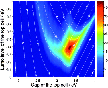 | ||
| Fig. 22 Percentage of increase of efficiency of the tandem cell over the best single cell for a device comprised of a P3HT:PCBM bottom sub-cell, and a top sub-cell based on a variable donor. The lines indicate the efficiency of the tandem devices. | ||
The second case considered is a tandem made of PCPDTBT:PCBM as the top cell, combined with a variable bottom cell. The optical band gap of this material is assumed to be 1.55 eV. Combined with a EHOMO2 of −5.3 eV as measured by Mühlbacher et al.60 this suggests ELUMO2 = −3.75 eV and an ideal VOC2 = 0.7 V is very close to the value measured by Kim et al.49 Thus, in this calculation, we have fixed ELUMO2 and EG2 and varied ELUMO1 and EG1. The result is displayed in Fig. 23. Interestingly, Fig. 23 suggests that the ultimate efficiency of 10% identified by Scharber et al.17 for a single cell based on a donor having [ELUMO1 = −4.0 eV; EG1 = 1.8 eV] can be pushed towards 13% by stacking a PCPDTBT:PCBM device on top of it.
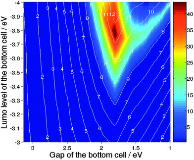 | ||
| Fig. 23 Percentage of increase in efficiency of the tandem cell over the best single cell for a device comprised of a PCPDTBT:PCBM top sub-cell, and a bottom sub-cell based on a variable donor. The lines indicate the efficiency of the tandem devices. | ||
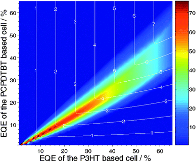 | ||
| Fig. 24 Percentage of increase in efficiency of the tandem cell over the best single cell (R) for a device comprised of a PCPDTBT:PCBM top sub-cell, and a P3HT:PCBM bottom sub-cell. The variables are the EQEs of both cells. The lines indicate the efficiency of the tandem devices. | ||
By plotting PCPDTBT on Fig. 22 or P3HT in Fig. 23, it appears that stacking these two materials would not allow increasing of their individual potential. However, such tandem devices still yield higher efficiencies than the best single cells realized so far, as proven by Kim et al.49 In order to substantiate this statement we have carried out the following calculations: By fixing [ELUMO1 = −3.3 eV; EG1 = 1.9 eV] and [ELUMO2 = −3.75 eV; EG2 = 1.55 eV] that is stacking PCPDTBT:PCBM on the top of P3HT:PCBM, we have calculated the ratio R for EQE1 and EQE2 comprises between 0 and 65%. Fig. 24 illustrates these results as well as the line of equal efficiency of the tandem devices. The part of the graph located above the line of equal efficiency diagonal indicates the region where the bottom cell limits the efficiency of the tandem device, while the part situated below this line indicates the region where the top device is the limitation. Fig. 24 confirms that if one could realize a PCPDTBT:PCBM cell showing 65% EQE on average, processing it on the top of a P3HT:PCBM would not increase the potential of the device. However, this statement has to be revised for PCPDTBT:PCBM cells having lower average EQE. For example, if the EQE of the low band gap cell is only 40%, then combining it with an efficient P3HT:PCBM device would enhance its performance by almost 40%.
This observation suggests that realizing tandem devices can be highly beneficial to enhance the performance of devices based on materials unable to deliver their full potential. All of the experimental examples cited in this review, whether they have been realized within the framework of evaporated small molecules or solution-processed polymers, correspond to this very situation. The tremendous increase in efficiency achieved by Yakimov et al. is based on the fact that the single devices were behaving far below their potential because of the low current induced by a thin thickness.27 Similarly the achievement of Kim et al.49 relies on the fact that the PCPDTBT:PCBM single cell does show an average EQE of only 30% over the range 350–800 nm.
In conclusion, we have shown that realizing tandem cells by connecting two sub-devices in series does not always push forward the potential of these single cells. However, when the donor materials employed in organic solar cells yield performances below their capabilities, tandem devices can be highly beneficial. Moreover, our calculations suggest that tandem cells showing efficiencies of 15% can be envisaged provided that properties needed from the materials are achieved.
5. Conclusion
So far, in the field of organic solar cells, a vast variation in designs which combine two or more individual single cells as a tandem structure have been considered, from small molecule evaporated materials up to fully solution-processed approaches, with various types of intermediate layers. The most efficient tandem organic solar cell reported by Heeger's group has around 6.5% power conversion efficiency. According to a set of design rules specifically derived for organic tandem cells, maximum efficiencies of 15% are expected for an optimized material couple. The recent trend of improving the tandem organic solar cell (Fig. 21) and design rules for the donor polymers in BHJ solar cells suggest that tandem architecture offers plenty of opportunity for further improvement, enough eventually to make plastic solar cells a practical option in rooftop solar panels. For this application, further efficiency strides could be achieved by more efficient new materials, more functional intermediate layers and better matching of the materials with complimentary absorption spectra.References
- (a) U. Cubasch, G. A. Meehl, in Climate Change 2001: The Scientific Basis, Ed. J. T. Houghton, Cambridge Univ. Press, Cambridge, 2001, 525–582 Search PubMed; (b) T. M. L. Wigley and S. C. B. Raper, Science, 2001, 293, 451 CrossRef CAS.
- (a) J. C. Orr, V. J. Fabry, O. Aumont, L. Bopp and S. C. Doney, Nature, 2005, 437, 681 CrossRef CAS; (b) A. J. Andersson, F. T. Mackenzie and A. Lerman, Global Biogeochem. Cycles, 2006, 20 , GB1S92; (c) T. R. Karl and K. E. Trenberth, Science, 2003, 302, 1719 CrossRef CAS.
- 2006 Key World Energy Statistics, International Energy Agency, 2006. Available at http://www.iea.org Search PubMed.
- (a) C. J. Cambell, The end of the first half of the age of oil, IV International Workshop on Oil and Gas Depletion, Lisbon, Portugal, 2005 Search PubMed; (b) Q. Y. Meng and R. W. Bentley, Energy, 2008, 33, 1179–1184 CrossRef; (c) R. W. Bentley, Global oil & gas depletion: an overview, Energy Policy, 2002, 30, 189–205 CrossRef.
- (a) Renewables in global energy supply: An IEA factsheet, International Energy Agency January 2007. Available at http://www.iea.org Search PubMed; (b) WEC (World Energy Council), New Renewable Energy Resources: A Guide to the Future, Kogan Page Limited, London, 1994 Search PubMed; (c) D. M. Kammen, The rise of renewables, Sci. Am., September 2006 Search PubMed.
- Q. Schiermier, J. Tollefson, T. Scully, A. Witze and O. Morton, Nature, 2008, 454, 816 CrossRef.
- World Energy Assessment Overview, 2004 Update, Ed. J. Goldemberg, T. B. Johansson, United Nations Development Programme, New York, 2004. Available at: http://www.undp. org/energy/weaover2004.htm Search PubMed.
- A. Jäger-Waldau, PV Status Report 2007, Institute for Environment and Sustainability, European Commission, 2007 Search PubMed.
- (a) C. J. Brabec, Sol. Energy Mater. Sol. Cells, 2004, 83, 273 CrossRef CAS; (b) C. J. Brabec, N. S. Sariciftci and J. C. Hummelen, Adv. Funct. Mater., 2001, 11, 15 CrossRef CAS.
- (a) B. C. Thompson and J.-M. J. Fréchet, Angew. Chem., Int. Ed., 2008, 47, 58–77 CrossRef; (b) R. Kroon, M. Lenes, J. C. Hummelen, P. W. M. Blom and B. de Boer, Polym. Rev., 2008, 48, 531–582 Search PubMed.
- J. Peet, J. Y. Kim, N. E. Coates, W. L. Ma, D. Moses, A. J. Heeger and G. C. Bazan, Nat. Mater., 2007, 6, 497 CrossRef CAS.
- M. A. Green, K. Emery, Y. Hisikawa and W. Warta, Prog. Photovoltaics: Res. Appl., 2008, 16, 81 Search PubMed.
- R. Gaudiana and C. J. Brabec, Nat. Photonics, 2008, 2, 287 Search PubMed.
- S. Shockley and H. J. Queisser, J. Appl. Phys., 1961, 32, 510 CAS.
- American Society for Testing and Materials (AST(M) Standard G159, West Conshoken, PA, USA. Source: http://rredc.nrel.gov/solar/spectra/am1.5/.
- G. Dennler, N. S. Sariciftci and C. J. BrabecConjugated Polymer-Based Organic Solar Cells, in Semiconducting Polymers, 2nd edn, Ed. Hadziioannou and Malliaras, Wiley-VCH Verlag GmbH, Weinheim, 2006 Search PubMed.
- M. C. Scharber, D. Mühlbacher, M. Koppe, P. Denk, C. Waldauf, J. Heeger and C. J. Brabec, Adv. Mater., 2006, 18, 789 CrossRef CAS.
- (a) A. Cravino, Appl. Phys. Lett., 2007, 91, 243502 CrossRef; (b) K. Vandewal, A. Gadisa, W. D. Oosterbaan, S. Bertho, F. Banishoeib, I. V. Severen, L. Lutsen, T. J. Cleij, D. Vanderzande and J. V. Manca, Adv. Funct. Mater., 2008, 18, 2064 CrossRef CAS.
- P. Würfel, Physics of Solar Cells, Wiley VCH, 2004 Search PubMed.
- A. De Vos, J. Phys. D: Appl. Phys., 1980, 13, 839 CrossRef.
- (a) M. A. Green, K. Emery, Y. Hisikawa and W. Warta, Prog. Photovoltaics: Res. Appl., 2007, 15, 425 Search PubMed; (b) M. Wanlass, P. Ahrenkiel, D. Albin, J. Carapella, A. Duda, K. Emery, D. Firedman, J. Geisz, K. Jones, A. Kibbler, J. Kiehl, S. Kurtz, W. McMahon, T. Moriarty, J. Olson, A. Ptak, M. Romero, S. Ward, 4th World Conference on Photovoltaic Energy Conversion (WCEP-4), Hawaii, May 2006, 729 Search PubMed.
- P. W. Blom, V. D. Mihailetchi, L. J. A. Koster and D. E. Markov, Adv. Mater., 2007, 19, 1551 CrossRef CAS.
- J. Grieschner, J. Cornil and H.-J. Egelhaaf, Adv. Mater., 2007, 19, 173–191 CrossRef CAS.
- A. Hadipour, B. de Boer and P. W. M. Blom, Org. Electron., 2008, 9, 617 CrossRef.
- G. Dennler, M. C. Scharber, T. Ameri, P. Denk, K. Forberich, C. Waldauf and C. J. Brabec, Adv. Mater., 2008, 20, 579 CrossRef CAS.
- M. Hiramoto, M. Suezaki and M. Yokoyama, Chem. Lett., 1990, 327 CrossRef CAS.
- A. Yakimov and S. R. Forrest, Appl. Phys. Lett., 2002, 80, 1667 CrossRef CAS.
- P. Peumans, A. Yakimov and S. F. Forrest, J. Appl. Phys., 2003, 93, 3693 CrossRef CAS.
- U. Kreibig and M. Vollmer, Optical Properties of Metal Clusters, Springer, Berlin, 1995 Search PubMed.
- B. P. Rand, P. Peumans and S. R. Forrest, J. Appl. Phys., 2004, 96(12), 7519 CrossRef CAS.
- J. Xue, S. Ushida, B. P. Rand and S. T. Forrest, Appl. Phys. Lett., 2004, 85, 5757 CrossRef CAS.
- G. Yu, J. Gao, J. C. Hummelen, F. Wudl and A. J. Heeger, Science, 1995, 270, 1789 CrossRef CAS.
- B. Maennig, J. Drechsel, D. Gebeyehu, P. Simon, F. Kozlowski, A. Werner, F. Li, S. Grundmann, S. Sonntag, M. Koch, K. Leo, M. Pfeiffer, H. Hoppe, D. Meissner, N. S. Sariciftci, I. Riedel, V. Dyakonov and J. Parisi, Appl. Phys. A, 2004, 79, 1 CrossRef CAS.
- (a) Z. Knittl, in Optics of Thin Films, Wiley, London, 1976 Search PubMed; (b) L. A. A. Pettersson, L. S. Roman and O. Inganas, J. Appl. Phys., 1999, 86, 487 CrossRef CAS; (c) H. Hoppe, N. Arnold, D. Meissner and N. S. Sariciftci, Thin Solid Films, 2004, 451, 589 CrossRef.
- J. Y. Kim, S. H. Kim, H. H Lee, K. Lee, W. Ma, X. Gong and A. J. Heeger, Adv. Mater., 2006, 18, 572 CrossRef CAS.
- J. Drechsel, B. Maennig, K. Kozlowski, M. Pfeiffer and K. Leo, Appl. Phys. Lett., 2005, 86, 244102 CrossRef.
- M. Pfeiffer, A. Beyer, B. Plönnigs, A. Nollau, T. Fritz, K. Leo, D. Schlettwein, S. Hiller and D. Wöhrle, Sol. Energy Mater. Sol. Cells, 2000, 63, 83 CrossRef CAS.
- A. G. Werner, F. Li, K. Harada, M. Pfeiffer, T. Fritz and K. Leo, Appl. Phys. Lett., 2003, 82, 4495 CrossRef CAS.
- K. Triyana, T. Yasuda, K. Fujita and T. Tsutsui, Thin Solid Films, 2005, 477, 198 CrossRef CAS.
- K. Triyana, T. Yasuda, K. Fujita and T. Tsutsui, Jpn. J. Appl. Phys., 2004, 43, 2352 CrossRef CAS.
- K. Kawano, N. Ito, T. Nishimori and J. Sakai, Appl. Phys. Lett., 2006, 88, 73514 CrossRef.
- G. Dennler, H.-J. Prall, R. Koeppe, M. Egginger, R. Autengruber and N. S. Sariciftci, Appl. Phys. Lett., 2006, 89, 73502 CrossRef.
- L. Chen, D. Godovski, O. Inganäs, J. C. Hummelen, R. A. J. Janssen, M. Svensson and M. R. Andersson, Adv. Mater., 2000, 12, 1367 CrossRef CAS.
- (a) A. Colsmann, J. Junge, C. Kayser and U. Lemmer, Appl. Phys. Lett., 2006, 89, 203506 CrossRef; (b) A. G. F. Janssen, T. Riedl, S. Hamwi, H.-H. Johannes and W. Kowalsky, Appl. Phys. Lett., 2007, 91 Search PubMed 073519.
- A. Hadipour, B. de Boer, J. Wildeman, F. B. Kooistra, J. C. Hummelen, M. G. R. Turbiez, M. M. Wienk, R. A. J. Janssen and P. W. M. Blom, Adv. Funct. Mater., 2006, 16, 1897 CrossRef CAS.
- J. Gilot, M. M. Wienk and R. A. J. Janssen, Appl. Phys. Lett., 2007, 90, 143512 CrossRef.
- (a) C. Pacholski, A. Kornowski and H. Weller, Angew. Chem., Int. Ed., 2002, 41, 1188 CrossRef CAS; (b) W. J. E. Beek, M. M. Wienk, M. Kemerink, X. Yang and R. A. J. Janssen, J. Phys. Chem. B, 2005, 109, 9505 CrossRef CAS.
- F. Verbakel, S. C. J. Meskers and R. A. J. Janssen, Appl. Phys. Lett., 2006, 89, 102103 CrossRef.
- J. Y. Kim, K. Lee, N. E. Coates, D. Moses, T.-Q. Nguyen, M. Dante and A. J. Heeger, Science, 2007, 317, 222 CrossRef CAS.
- G. Dennler, K. Forberich, T. Ameri, C. Waldauf, P. Denk, C. J. Brabec, K. Hingerl and A. J. Heeger, J. Appl. Phys., 2007, 102, 123109 CrossRef.
- J. Y. Kim, S. H. Kim, H.-H. Lee, K. Lee, W. Ma, X. Gong and A. J. Heeger, Adv. Mater., 2006, 18, 572–576 CrossRef CAS.
- V. Shrotriya, E. Hsing-En, G. Li, Y. Yao and Y. Yang, Appl. Phys. Lett., 2006, 88 Search PubMed 064104.
- A. Hadipour, B. de Boer and P. W. M. Blom, J. Appl. Phys., 2007, 102 Search PubMed 074506.
- N.-K. Persson and O. Inganäs, Sol. Energy Mater. Sol. Cells, 2006, 90, 3491 CrossRef CAS.
- K. Tvingstedt, V. Andersson, F. Zhang and O. Inganas, Appl. Phys. Lett., 2007, 91, 123514 CrossRef.
- G. Dennler, K. Forberich, M. C. Scharber, C. J. Brabec, I. Tomis, K. Hingerl and T. Fromherz, J. Appl. Phys., 2007, 102 Search PubMed 054516.
- C. Zhang, S. W. Tong, C. Jiang, E. T. Kang, D. S. H. Chan and C. Zhu, Appl. Phys. Lett., 2008, 92 Search PubMed 083310.
- Y. Kim, M. Shin, I. Lee, H. Kim and S. Heutz, Appl. Phys. Lett., 2008, 92 Search PubMed 093306.
- O. Hagemann, M. Bjerring, N. C. Nielsen and F. C. Krebs, Sol. Energy Mater. Sol. Cells, 2008, 92, 1327 CrossRef CAS.
- D. Mühlbacher, M. C. Scharber, M. Morana, Z. Zhu, D. Waller, R. Gaudiana and C. J. Brabec, Adv. Funct. Mater., 2006, 16, 2884.
| This journal is © The Royal Society of Chemistry 2009 |
