Inelastic electron tunneling spectra and vibronic coupling density analysis of 2,5-dimercapto-1,3,4-thiadiazole and tetrathiafulvalene dithiol
Katsuyuki
Shizu
a,
Tohru
Sato
*ab and
Kazuyoshi
Tanaka
a
aDepartment of Molecular Engineering, Graduate School of Engineering, Kyoto University, Kyoto, 615-8510, Japan. E-mail: tsato@scl.kyoto-u.ac.jp; Fax: +81-75-383-2556; Tel: +81-75-383-2803
bFukui Institute for Fundamental Chemistry, Kyoto University, Takano-Nishihiraki-cho 34-4, Sakyo-ku, Kyoto 606-8103, Japan
First published on 11th August 2010
Abstract
We calculate inelastic electron tunneling (IET) spectra for 2,5-dimercapto-1,3,4-thiadiazole (DMcT) and tetrathiafulvalene dithiol (TTF-DT) sandwiched between two gold electrodes using non-equilibrium Green's function (NEGF) theory. The calculated peak positions are in reasonable agreement with the experimental data. We also calculate IET spectrum for thiophene dithiol (Th-DT) sandwiched between two gold electrodes and compare it with that for the Au/DMcT/Au junction. Th-DT and DMcT can be distinguished using the IET spectroscopy by the peak of the C–C stretching mode. The peak intensity in the IET spectra is analyzed using vibronic coupling density (VCD) analysis. For the Au/DMcT/Au junction, large distribution of electron-density difference ΔρHOMO on the C–N bond is responsible for the intense peak of the C–N stretching mode; on the other hand, for Au/TTF-DT/Au junction, large distribution of ΔρHOMO on the central C![[double bond, length as m-dash]](https://www.rsc.org/images/entities/char_e001.gif) C bond is responsible for the intense peak of the CC stretching modes.
C bond is responsible for the intense peak of the CC stretching modes.
Introduction
Inelastic electron tunneling (IET) spectra for metal–molecule–metal junctions have been studied extensively in recent years.1–6 Peak positions of an IET spectrum correspond to vibrational energies of a molecule that interacts with a carrier, and peak heights reflect relative strength of electron–molecule vibration interaction, or vibronic coupling.7 Thus, IET spectra contain information about vibronic coupling between the carrier and the molecular vibrations. IET spectra are characteristic for molecules and IET spectroscopy can be an identification method for molecular species adsorbed on an electrode. IET spectra are also useful for choosing a molecule when we construct a molecular wire junction, and therefore, a fundamental understanding of IET spectra is needed for development of future nanoelectronics.Selection rules for IET spectra are as yet controversial. For oligo (phenylene ethynylene) (OPE), the ring mode and C![[triple bond, length as m-dash]](https://www.rsc.org/images/entities/char_e002.gif) C stretching mode show intense peaks; for oligo (vinylene ethynylene) (OPV), the ring mode and CC stretching mode show intense peaks.4 This result shows that the carrier is scattered by IR and Raman active modes. In contrast, the systematic experimental observation of the IET spectra for semifluorinated alkanethiol junctions has made it clear that the relative intensity of the spectra is not necessarily proportional to the calculated IR nor Raman intensities of the isolated semifluorinated alkanethiols.5 Using a scanning tunneling microscope (STM), Okabayashi et al. have measured high-resolution STM IET spectra of alkanethiol self-assembled monolayers (SAMs)8,9 and reported that inelastic intermolecular scattering is important in electron tunneling in the SAMs. Troisi et al. have estimated peak intensities in IET spectra by calculating the first derivative of the Green's function with respect to the normal mode coordinates, and concluded that only the totally symmetric modes show peak when a single tunneling channel is available.10
C stretching mode show intense peaks; for oligo (vinylene ethynylene) (OPV), the ring mode and CC stretching mode show intense peaks.4 This result shows that the carrier is scattered by IR and Raman active modes. In contrast, the systematic experimental observation of the IET spectra for semifluorinated alkanethiol junctions has made it clear that the relative intensity of the spectra is not necessarily proportional to the calculated IR nor Raman intensities of the isolated semifluorinated alkanethiols.5 Using a scanning tunneling microscope (STM), Okabayashi et al. have measured high-resolution STM IET spectra of alkanethiol self-assembled monolayers (SAMs)8,9 and reported that inelastic intermolecular scattering is important in electron tunneling in the SAMs. Troisi et al. have estimated peak intensities in IET spectra by calculating the first derivative of the Green's function with respect to the normal mode coordinates, and concluded that only the totally symmetric modes show peak when a single tunneling channel is available.10
Our purpose is to provide an understanding of relative intensities in IET spectra based on vibronic coupling density (VCD) analysis.11–14 The VCD analysis tells us the reason for relative order of strength of vibronic coupling, and hence, gives a new insight into the shape of an IET spectrum. We have applied the VCD analysis to various molecules, revealed a local picture of vibronic coupling in molecules, and shown that we can tune vibronic couplings by controlling electron-density difference Δρ.11–19 This guiding principle provides an effective way to design functional materials such as molecular wires, as well as to interpret IET spectra.
In this study, using the VCD analysis, we investigate vibronic coupling in 2,5-dimercapto-1,3,4-thiadiazole (DMcT) and tetrathiafulvalene dithiol (TTF-DT) sandwiched between two gold electrodes. We calculate IET spectra for the Au/DMcT/Au and Au/TTF-DT/Au junctions employing the non-equilibrium Green's function (NEGF) formalism20 and compare the spectra with the experimental results obtained using nanofabricated mechanically-controllable break junctions (MCBJs).6,21 Tetrathiafulvalene (TTF) and its derivatives have been studied as electron donors for molecular conductors and superconductors;22–24 DMcT has been known as a cathode-active material for lithium rechargeable batteries25 and an understanding of charge transfer between DMcT and metal electrodes is quite important. These molecules are promising building blocks for molecular wires and their conducting properties when sandwiched between gold electrodes have been investigated intensively.21,26,27
We also calculate an IET spectrum for an Au/thiophene dithiol (Th-DT)/Au junction and compare it with that for the Au/DMcT/Au junction. The VCD analysis reveals the reason for the difference between the spectra of the two junctions. This analysis provides a new insight for IET spectra and guiding principle of design for molecular wire junctions.
Theory
Vibronic coupling constant and vibronic coupling density
A molecular Hamiltonian can be written as![[script letter H]](https://www.rsc.org/images/entities/char_e142.gif) (r,R) = e(r,R) + (r,R) = e(r,R) + ![[scr T, script letter T]](https://www.rsc.org/images/entities/char_e533.gif) n(R) n(R) | (1) |
e(r,R) and n(R) are an electronic Hamiltonian and the nuclear kinetic energy, respectively. We assume that the molecular wire is in a neutral state at first, and vibronic coupling occurs when the molecule is ionized by a carrier.
Once an equilibrium nuclear configuration R0 and vibrational frequencies of the molecule are obtained, we can calculate vibronic coupling constant (VCC) Vαij for the αth mode:
 | (2) |
For i = j, Vαi (≡ Vαii) can be expressed as the space integration of the VCD ηαi:11–14
| Vαi = ∫ηαi(x)dx | (3) |
| ηαi = Δρi(x) × vα(x) | (4) |
| Δρi(x) = ρ+i(x) − ρ0(x) | (5) |
 | (6) |
The contribution to ηαi from the Ath atom is given by
| ηαi,A(x) = Δρ(x) × vα,A(x) | (7) |
The space integration of ηαi,A gives the contribution to Vαi from the Ath atom:
| Vαi,A = ∫ηαi,A(x)dx | (8) |
 | (9) |
Inelastic electron tunneling spectrum
Within the framework of the Holstein–Peierls model, we can write the molecular Hamiltonian in the second quantization form as | (10) |
 | (11) |
A Green's function of the molecular wire junction is given by
| G(E) = [EI − He − Σ(E)]−1 | (12) |
e, and Σ(E) is a total self-energy,20 which is defined later by eqn (27). He is a diagonal matrix and (He)ii = εi.
Inscattering and outscattering functions for the left/right electrode is given by
| ΣL/Rin(E) = fL/R(E)ΓL/R(E) | (13) |
| ΣL/Rout(E) = (1 − fL/R(E))ΓL/R(E) | (14) |
 | (15) |
| ΓL/R(E) = i{ΣL/R(E) − Σ†L/R(E)} | (16) |
| ΣL/R(E) = τL/R†g(E)τL/R | (17) |
We calculate inscattering and outscattering functions for the vibronic coupling within the first Born approximation:28
 | (18) |
 | (19) |
| (λα)ij = λijα | (20) |
 | (21) |
| Gn(E) = G(E)Σin(E)G†(E) | (22) |
| Gp(E) = G(E)Σout(E)G†(E) | (23) |
| Σin(E) = ΣLin(E) + ΣRin(E) + ΣSin(E) | (24) |
| Σout(E) = ΣLout(E) + ΣRout(E) + ΣSout(E) | (25) |
A self-energy for vibronic coupling ΣS is a function of the energy E of the incoming electron and is related to ΣSin and ΣSout through the following equation:
| i{ΣS(E) − ΣS†(E)} = ΣSin(E) + ΣSout(E) | (26) |
Σ(E) is a sum of the self-energies:
| Σ(E) = ΣL(E) + ΣR(E) + ΣS(E) | (27) |
G n and Gp are calculated self-consistently using eqn (12), (18), (19), and (22)–(27).
The electric current through the molecular wire junction is given by
 | (28) |
Method of calculation
All the DFT calculations were done using Gaussian 03 software.29 For carbon, hydrogen, nitrogen, and sulfur atoms the 6-311+G* basis set was used; for gold atoms, LANL2DZ basis set was used. We considered intramolecular vibronic coupling in the molecules containing gold atoms: terminal hydrogen atoms of DMcT, TTF-DT, and Th-DT are replaced by gold atoms. We denote them as Au2DMcT, Au2TTF-DT, and Au2Th-DT, respectively.Geometry optimization and vibrational analysis of neutral Au2DMcT, Au2TTF-DT, and Au2Th-DT were done using the B3LYP method. We assumed C2v symmetry for Au2DMcT, Ci symmetry for Au2TTF-DT, and C2 symmetry for Au2Th-DT. We calculated wavefunctions of the cationic states in which the electron is removed from the HOMO (denoted as |Ψ+HOMO〉) using the UB3LYP method and that in which the electron is removed from the next HOMO (denoted as |Ψ+HOMO–1〉) using the CASSCF method. The active space of our CASSCF calculation includes three electrons and three molecular orbitals (LUMO, HOMO, and next HOMO).
We calculated conductances and IET spectra for Au2DMcT, Au2TTF-DT, and Au2Th-DT sandwiched between two gold electrodes (denoted as Au/DMcT/Au, Au/TTF-DT/Au, and Au/Th-DT/Au, respectively). We adopt the Green's function for a semi-infinite one-dimensional gold chain as g.20 The coupling between a molecule and electrode τL/R depends on device geometry and molecular orientation. However, since the junction geometry is unclear, we consider τL/R as a parameter.
We adopt the opposite sign of the work function of a gold surface (5.53 eV)30 as the Fermi energy of the electrode surface EF. The electrochemical potential μL/R at an applied bias voltage Vb is set to be μL/R = EF ± eVb/2.
Results and discussion
Vibronic coupling density analysis
Fig. 1 shows the optimized geometries of neutral Au2DMcT and Au2TTF-DT with atomic numbering schemes. The optimized geometry of Au2DMcT is planar. The optimized bond angles and lengths of Au2DMcT are in good agreement with the experimental values of 2-amino-5-phenyl-1,3,4-thiadiazole;31 the optimized bond angles and lengths of Au2TTF-DT are in agreement with the experimental data for TTF obtained by Cooper et al.32 The dihedral angles S1–C1–C1′–S2′, S2–C1–C1′–S1, C1′–C1–S1–C2, and C1′–C1–S2–C3 are 0.5°,179.5°, 179.4°, and 178.7°, respectively, suggesting that the central TTF moiety is almost planar. Au2DMcT and Au2TTF-DT have eight and 21 totally symmetric modes, respectively, that couple to the electronic state.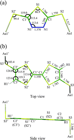 | ||
| Fig. 1 Optimized geometries with atomic numbering schemes: (a) Au2DMcT; (b) Au2TTF-DT. Bond lengths are in Å and bond angles in degrees. | ||
Calculated VCCs and peak positions in IET spectra for Au2DMcT and Au2TTF-DT together with the experimental data6,21 are listed in Tables 1 and 2, respectively. a(α) denotes the αth totally symmetric mode. VαHOMO/HOMO–1 is the VCC for the cation state in which the electron is removed from the HOMO/next HOMO:
 | (29) |
 | (30) |
| Mode | Peak position | V α HOMO | V α HOMO–1 | |||
|---|---|---|---|---|---|---|
| Calc. | Exp. | |||||
| cm−1 | mV | mV | ||||
| a(1) | C–S–Au bending | 26.91 | 3 | −0.02 | −0.07 | |
| a(2) | S–Au stretching | 131.17 | 16 | −0.08 | −0.17 | |
| a(3) | S–Au stretching | 351.23 | 44 | −0.13 | −1.05 | |
| a(4) | S–Au stretching | 361.13 | 45 | 26 | −1.01 | −0.52 |
| a(5) | C–S–C bending | 615.64 | 76 | 80 | −0.77 | −1.44 |
| a(6) | S–C–N stretching | 977.45 | 121 | −0.12 | −1.42 | |
| a(7) | N–N stretching | 1026.19 | 127 | 128 | −1.63 | −0.18 |
| a(8) | CN stretching |
1373.01 | 170 | 168 | −5.34 | −4.74 |
| Mode | Peak position | V α HOMO | |||
|---|---|---|---|---|---|
| Calc. | Exp. | ||||
| cm−1 | mV | mV | |||
| a(10) | C–S stretching | 452.55 | 56 | 82 | −1.09 |
| a(13) | C–S stretching | 609.31 | 76 | −0.31 | |
| a(15) | C–S stretching | 790.62 | 98 | 105 | −0.37 |
| a(18) | in-plane C–C–H bending | 1181.96 | 147 | 142 | −0.17 |
| a(19) | CC stretching |
1458.59 | 181 | −2.70 | |
| a(20) | CC stretching |
1521.81 | 189 | 165 | −3.16 |
A scaling factor of 0.96333 was used for theoretical frequencies.
Fig. 2 shows vibrational modes with the three largest VαHOMO: the a(4), a(7), and a(8) modes of Au2DMcT; the a(10), a(19), and a(20) modes of Au2TTF-DT. The direction of the vibrational modes is chosen such that VαHOMO is negative.
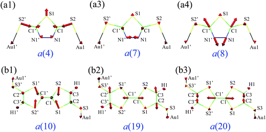 | ||
| Fig. 2 Vibrational modes with the large VαHOMO: (a1) a(4), (a2) a(7), and (a3) a(8) modes of Au2DMcT; (b1) a(10), (b2) a(19), and (b3) a(20) modes of Au2TTF-DT. | ||
First, we discuss VαHOMO using the vibronic coupling density analysis. For Au2DMcT, the CN stretching mode (the a(8) mode) has quite a large VCC. The N–N stretching (the a(7) mode) and S–Au stretching modes (the a(4) mode) have relatively large VCCs. The C–S–C bending and N–N stretching modes (the a(5) and a(6) modes) have small VCCs.
For Au2TTF-DT, the CC stretching modes (the a(19) and a(20) modes) have large VCCs, and the C–S stretching mode (the a(10) mode) has a relatively large VCC. For the a(19) mode, the phase of the stretching vibration of the central CC double bond is the same as that of terminal CC double bonds, that is, the three CC double bonds lengthen/shorten simultaneously; for the a(20) mode, the phases are opposite, that is, when the central double bond lengthens/shortens, the terminal double bonds shorten/lengthen.
Fig. 3(a) shows ΔρHOMO for Au2DMcT. ΔρHOMO is large on the C1–N1 bond, while it is small on the S1 and Au1 atoms. ΔρHOMO has also a large value on the S2 atom bonded to the terminal Au atom. On the N1–N1′ bond, ΔρHOMO is large only near the N atoms, and is not distributed in the middle of the bond. Positive regions have a σ-character and originate from the occupied molecular orbitals other than the HOMO. The positive regions weaken the repulsion between negative regions.
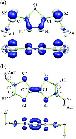 | ||
| Fig. 3 Electron-density difference ΔρHOMO: (a) Au2DMcT at an isosurface value of 0.005 a.u.; (b) Au2TTF-DT at an isosurface value of 0.004 a.u. White regions are positive; blue regions are negative. | ||
Fig. 3(b) shows ΔρHOMO for Au2TTF-DT. ΔρHOMO is more spread out for Au2TTF-DT than for Au2DMcT, because Au2TTF-DT is a larger π-conjugated system than is Au2DMcT. ΔρHOMO is distributed mainly on the S1 and S2 atoms and C1–C1′ bond. Positive regions around the C1 and C1′ atoms relax repulsion between the negative regions above and below the C1–C1′ bond. ΔρHOMO is small around the C2, C3, H1, S3, and Au1 atoms.
Fig. 4(a1–3) shows derivative of the nuclear–electronic potential vα for the a(4), a(7), and a(8) modes of Au2DMcT. A head and tail of an arrow in Fig. 2 correspond to blue and white regions in Fig. 4. Numbers in Fig. 4 are AVCCs in 10−4 a.u.
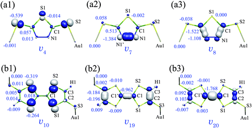 | ||
| Fig. 4 Derivative of nuclear–electronic potential vα: (a1) a(4), (a2) a(7), and (a3) a(8) modes of Au2DMcT at an isosurface value of 0.02 a.u.; (b1) a(10), (b2) a(19), and (b3) a(20) modes of Au2TTF-DT at an isosurface value of 0.01 a.u. White regions are positive; blue regions are negative. Numbers are atomic vibronic coupling constants VαHOMO,A (10−4 a.u.). | ||
The a(8) mode is the CN stretching mode and v8 is large on the C1–N1 bond (Fig. 4(a3)). Since ΔρHOMO is also large on the C1–N1 bond (Fig. 3(a)), v8 and ΔρHOMO overlap significantly on the bond. Hence, η8 has a large value on the CN double bonds, and the C and N atoms have large AVCCs (−1.522 and −1.108 × 10⁻⁴ a.u., respectively).
The a(7) mode is the N–N stretching mode and v7 is largely distributed on the N1–N1′ bond (Fig. 4(a2)). However, since ΔρHOMO is small in the middle of the N1–N1′ bond, the region in which η7 is large is limited around the N atoms. Hence, only the N atoms have large AVCCs (–1.384 × 10⁻⁴ a.u.), and V7HOMO is smaller than V8HOMO.
The a(4) mode is the S–Au stretching mode, and v4 is large around the S2 atom (Fig. 4(a1)). v4 and ΔρHOMO overlap on the S2 atom, however, since the extent of the overlap is small, the AVCC of the S2 atom (–0.539 × 10⁻⁴ a.u.) is smaller than that of the N1 atom for the a(7) mode (–1.384 × 10⁻⁴ a.u.). Hence, V4HOMO is smaller than V7HOMO. Thus, we can understand the reason for the relative order of the VCCs by analyzing the VCD distributions.
Fig. 4(b1–3) shows vα for the a(10), a(19), and a(20) modes of Au2TTF-DT. The a(19) and a(20) modes are CC stretching modes, and hence, v19 and v20 are large on the CC double bonds. Since v19 and v20 overlap significantly with ΔρHOMO on the C1–C1′ bond, η19 and η20 are large on the bond, which leads to the large AVCCs of the C1 and C1′ atoms: −0.962 × 10⁻⁴ a.u. for the a(19) mode; −1.768 × 10⁻⁴ a.u. for the a(20) mode.
The a(10) mode includes C1–S1 and C1–S2 stretching vibrations and v10 is large around the S1 and S2 atoms. v10 and ΔρHOMO are distributed around the S1 and S2 atoms. However, the overlap between them is small compared with those for the a(19) and a(20) modes. Hence, the AVCCs of S1 and S2 atoms for the a(10) mode are smaller than that of the C1 atom for the a(19) and a(20) modes. This is the reason why V10HOMO (= −1.09 × 10⁻⁴ a.u.) is smaller than those of V19HOMO (= −2.70 × 10⁻⁴ a.u.) and V20HOMO (= −3.16 × 10⁻⁴ a.u.).
For the a(19) and a(20) modes, the AVCCs of the atoms other than the carbon atoms are quite small. The sums of the AVCCs of the carbon atoms for the a(19) and a(20) modes are −2.684 × 10⁻⁴ and −3.146 × 10⁻⁴ a.u., respectively, which correspond to 99.4% of V19HOMO and 99.6% of V20HOMO, suggesting that vibronic coupling occurs mainly on the carbon atoms. V20HOMO is larger than V19HOMO, because for the a(20) mode, the AVCC of the C1 atom is much larger than that for the a(19) mode, which originates from the fact that v20HOMO is larger than v19HOMO on the C1–C1′ bond.
Second, we discuss the relative VαHOMO–1 ordering for Au2DMcT. The a(8) mode has quite a large VαHOMO–1 and the a(3), a(5), and a(6) modes have relatively large VαHOMO–1 values (Table 1). The difference between the order of VαHOMO–1 and VαHOMO reflects the difference between the distribution pattern of ΔρHOMO–1 and ΔρHOMO.
Fig. 5(a) shows ΔρHOMO–1 for Au2DMcT. In contrast to ΔρHOMO (Fig. 3(a)), ΔρHOMO–1 is largely distributed on the S1 and Au1 atoms and is not largely distributed on the middle of the C1–N1 bond. Moreover, ΔρHOMO–1 is larger on the C1 atom than on the N1 atom. Hence, vibronic coupling in the sate |Ψ+HOMO–1〉 is strong around the S1, C1, and Au1 atoms compared with that in the sate |Ψ+HOMO〉.
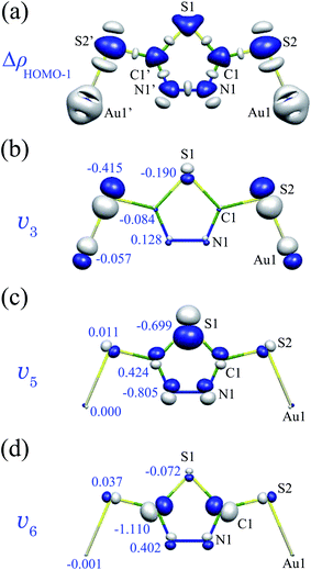 | ||
| Fig. 5 (a) Electron-density difference ΔρHOMO–1 for Au2DMcT at an isosurface value of 0.01 a.u.; (b) v3, (c) v5, and (d) v6 of Au2DMcT at an isosurface value of 0.02 a.u. Numbers in (b–d) are atomic vibronic coupling constants VαHOMO–1,A (10−4 a.u.). | ||
Fig. 5(b–d) shows v3 (S–Au stretching), v5 (C–S–C bending), and v6 (S–C–N bending) for Au2DMcT. v3 overlaps with ΔρHOMO–1 on the S1 and S2 atoms, which leads to the large AVCCs of the S1 and S2 atoms; v5 overlaps with ΔρHOMO–1 on the S1 and N1 atoms, which leads to the large AVCCs of the S1 and N1 atoms; v6 overlaps with ΔρHOMO–1 on the C1 atom, which leads to the large AVCC of the C1 atom. The large VαHOMO–1 of the a(8) mode is due to the significant overlap between ΔρHOMO–1 and v8 on the C1 and N1 atoms.
Inelastic electron tunneling spectra
The energy levels of HOMO of Au2DMcT and Au2TTF-DT are −6.08 and −5.16 eV, respectively, and the HOMO is the closest to the Fermi level of the electrode (–5.53 eV). An energy gap between the Fermi level of the electrode and the HOMO is small for the Au/TTF-DT/Au junction, suggesting that a carrier transport occurs more efficiently through the Au/TTF-DT/Au junction than through the Au/DMcT/Au junction.For the Au/DMcT/Au junction, τL/R was scaled to produce the experimental conductance6 (0.008G0 at Vb = 0.2 V) and for the Au/TTF-DT/Au and Au/Th-DT/Au junctions, the same τL/R value was used. We calculate the IET spectra for the Au/DMcT/Au junction assuming that an electron tunneling occurs through the HOMO and next HOMO. The two molecular orbitals belong to different irreducible representations: the HOMO and next HOMO are the a2 and b1 orbitals, respectively. Therefore the off-diagonal VCCs vanish:
 | (31) |
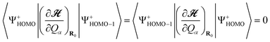
Fig. 6(a) shows calculated IET spectra for the Au/DMcT/Au junction at T = 4.2, 10, and 20 K. At T = 4.2 K, the a(4), a(5), a(7), and a(8) modes show peaks. At T = 10 and 20 K, the peak due to the a(5) mode is not seen clearly because of the thermal broadening of the peak, that is, the broadening of the Fermi distribution function fL/R.
 | ||
| Fig. 6 (a) Calculated inelastic electron tunneling spectra for Au/DMcT/Au junction at various temperatures. The solid line shows the spectrum at T = 4.2 K; dashed line shows the spectrum at T = 10 K; dot-dashed line shows the spectrum at T = 20 K. (b) Comparison of calculated and experimental inelastic electron tunneling spectra for Au/DMcT/Au junction at T = 4.2 K. Solid line shows the calculated spectrum; dotted line shows the experimental spectrum.6 (c) Calculated inelastic electron tunneling spectra for Au/DMcT/Au junction at T = 4.2 K assuming that the electron tunneling occurs through only the HOMO. | ||
Calculated full-width at half-maximum (FWHM) of the peak of the N–N stretching mode (the a(7) mode) is 8, 11, and 23 mV, respectively, at T = 4.2, 10, and 20 K. These values are small compared with the experimental data (25, 30, 38 mV, respectively).6 In our calculation, only the thermal broadening influences the peak widths. The difference between the theoretical and experimental peak widths may originate primarily from instrumental broadening.
Fig. 6(b) shows comparison of the calculated and experimental IET spectra for the Au/DMcT/Au junction at T = 4.2 K. The experimental d2I/dVb2 values are scaled to fit the calculated spectrum at Vb = 127 mV (the peak position of the N–N stretching mode). Peaks corresponding to the a(4), a(5), a(7), and a(8) modes were observed experimentally.6 In the experimental spectrum, d2I/dVb2 has a large value near the zero-bias region, which is called the zero-bias anomaly.5 The zero-bias anomaly may originate from phonon scattering in the electrodes. For Vb > 0.05 V, the order of the relative intensity of the spectra agrees well. The relative intensity increases in the order: a(5) < a(7) < a(8). By comparing the spectra, the intensity for the a(5) mode (C1–S2 stretching) is underestimated, while that for the a(8) mode (C1–N1 stretching) is overestimated.
Fig. 6(c) shows the calculated IET spectrum for the Au/DMcT/Au junction at T = 4.2 K assuming that the electron tunneling occurs through only the HOMO. Comparing Fig. 6(c) with Fig. 6(b), the two calculated IET spectra are almost identical. This is because the difference between the orbital energy of the next HOMO (–7.07eV) and the Fermi energy of the electrode (–5.53 eV) is large and the vibronic couplings in the state |Ψ+HOMO–1〉 make little contribution to the IET spectrum. This result suggests that an inelastic electron tunneling occurs mainly through the HOMO. For the Au/TTF-DT/Au and Au/Th-DT/Au junctions, we consider the inelastic electron tunneling via only the HOMO.
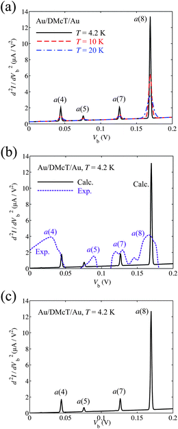
Fig. 7 shows calculated IET spectrum for the Au/TTF-DT/Au junction at 4.2 K. The a(10), a(19), and a(20) modes show strong peaks. Peaks due to the a(10), a(15), and a(20) modes were observed experimentally for Au/TTF/Au junction.21 Although the a(19) mode has the large VCC, since the peak position of the mode is close to that of the a(20) mode, the peak of the a(19) mode would be superimposed with the peak of the a(20) mode and would not be observed in the experimental IET spectrum.
 | ||
| Fig. 7 Calculated inelastic electron tunneling spectrum for Au/TTF-DT/Au junction at T = 4.2 K. | ||
Comparison of IET spectra for the Au/Th-DT/Au and Au/DMcT/Au junctions
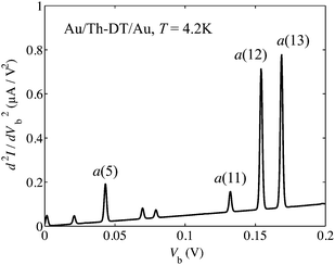
Molecular structure of Th-DT is similar to that of DMcT (nitrogen atoms in DMcT are replaced by –CH– groups in thiophene). Although there is no experimental assignment of IET spectra for the Au/Th-DT/Au junction, it is meaningful to compare the spectra for the Au/Th-DT/Au junction with that for the Au/DMcT/Au junction.Fig. 8 shows calculated IET spectra for Au/Th-DT/Au junction at T = 4.2 K. The major difference between the IET spectra for the Au/Th-DT/Au and Au/DMcT/Au junctions is the presence of the peak due to the a(13) mode (169 mV, Fig. 9(a)). The a(13) mode contains C2–C2′ stretching and C1–C2–H1 in-plane bending vibrations. For the Au/Th-DT/Au junction, two peaks are observed around 160 mV. In contrast, for the Au/DMcT/Au junction, only one peak is observed. Hence, thiophene and DMcT can be distinguished by the peak of the a(13) mode.
 | ||
| Fig. 8 Calculated inelastic electron tunneling spectrum for Au/Th-DT/Au junction at T = 4.2 K. | ||
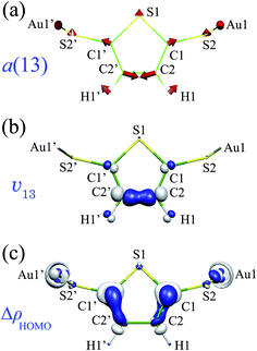 | ||
| Fig. 9 (a) The a(13) mode of Au2Th-DT; (b) derivative of nuclear–electronic potential v13 (= 0.02 a.u.); (c) electron-density difference ΔρHOMO (= 0.005 a.u.) of Au2Th-DT. | ||
The a(13) mode contains displacements of the C1, C2 and H1 atoms, and v13 is large on the C2–C2′ bond and around the C1 and H1 atoms (Fig. 9(b)). ΔρHOMO is also large around the C1 and C2 atoms (Fig. 9(c)). Hence, ΔρHOMO overlaps significantly with v13 on the C1 and C2 atoms. This is why the a(13) mode has a large VCC and shows the strong peak in the IET spectrum.
The IET spectrum for Au/Th-DT/Au junction is similar to that for the Au/DMcT/Au junction (Fig. 6(a)). This similarity originates from the similarity in the molecular structures and ΔρHOMO distributions. Since ΔρHOMO for Au2Th-DT is distributed on the C1, C2, and S2 atoms, vibrational modes in which these atoms are displaced show intense peaks; S–Au stretching mode (the a(5) mode, 44 mV), C–C stretching mode (the a(11) mode, 133 mV), and CC stretching mode (the a(12) mode, 155 mV).
Conclusions
We calculated the VCDs for Au2DMcT and Au2TTF-DT cations. The VCD analysis enables us to understand the relative order of the VCCs. For Au2DMcT, since ΔρHOMO is large on the C–N bond, the C–N stretching mode couples strongly to the electronic state; for Au2TTF-DT, since ΔρHOMO is large on the central CC bond, the CC stretching modes couple strongly to the electronic state.
We calculated the IET spectra for Au/DMcT/Au and Au/TTF-DT/Au junctions using the NEGF theory. We calculated the IET spectrum for the Au/Th-DT/Au junction and compared it with that for the Au/DMcT/Au junction. Th-DT and DMcT can be distinguished using the IET spectroscopy by the peak of the C–C stretching mode. The VCD analysis can be an effective way to understand relative intensities in IET spectra.
Acknowledgements
The authors thank Prof. Masateru Taniguchi (The Institute of Scientific and Industrial Research, Osaka University) for helpful discussions and allowing us to present his experimental data. Numerical calculations were performed partly at the Supercomputer Laboratory of Kyoto University and Research Center for Computational Science, Okazaki, Japan. This work was supported by a Grant-in-Aid for Scientific Research (C) (20550163), Priority Areas “Molecular theory for real systems” (20038028) from the Japan Society for the Promotion of Science (JSPS). This work was also supported in part by the Global COE Program “International Center for Integrated Research and Advanced Education in Materials Science” (No. B-09) of the Ministry of Education, Culture, Sports, Science and Technology (MEXT) of Japan, administered by JSPS.References
- S. Gregory, Phys. Rev. Lett., 1990, 64, 689–692 CrossRef CAS.
- W. Ho, J. Chem. Phys., 2002, 117, 11033–11061 CrossRef CAS.
- W. Wang, T. Lee, I. Kretzschmar and M. A. Reed, Nano Lett., 2004, 4, 643–646 CrossRef CAS.
- J. G. Kushmerick, J. Lazorcik, C. H. Patterson, R. Shashidhar, D. S. Seferos and G. C. Bazan, Nano Lett., 2004, 4, 639–642 CrossRef.
- J. M. Beebe, H. J. Moore, T. R. Lee and J. G. Kushmerick, Nano Lett., 2007, 7, 1364–1368 CrossRef CAS.
- M. Tsutsui, M. Taniguchi, K. Shoji, K. Yokota and T. Kawai, Nanoscale, 2009, 1, 164–170 RSC.
- M. Galperin, M. A. Ratner and A. Nitzan, J. Phys.: Condens. Matter, 2007, 19, 103201 CrossRef.
- N. Okabayashi, Y. Konda and T. Komeda, Phys. Rev. Lett., 2008, 100, 217801 CrossRef.
- N. Okabayashi, M. Paulsson, H. Ueba, Y. Konda and T. Komeda, Phys. Rev. Lett., 2010, 104, 077801 CrossRef.
- A. Troisi and M. A. Ratner, J. Chem. Phys., 2006, 125, 214709 CrossRef.
- T. Sato, K. Tokunaga and K. Tanaka, J. Chem. Phys., 2006, 124, 024314 CrossRef.
- K. Tokunaga, T. Sato and K. Tanaka, J. Chem. Phys., 2006, 124, 154303 CrossRef.
- K. Tokunaga, T. Sato and K. Tanaka, J. Mol. Struct., 2007, 838, 116–123 CrossRef CAS.
- T. Sato, K. Tokunaga, N. Iwahara, K. Shizu and K. Tanaka, Vibronic coupling constant and vibronic coupling density in The Jahn–Teller-Effect – Fundamentals and Implications for Physics and Chemistry, ed. H. Köppel, H. Barentzen and D. R. Yarkony, Springer-Verlag, Berlin and Heidelberg, 2009 Search PubMed.
- T. Sato, K. Tokunaga and K. Tanaka, J. Phys. Chem. A, 2008, 112, 758–767 CrossRef CAS.
- T. Sato, K. Shizu, T. Kuga, K. Tanaka and H. Kaji, Chem. Phys. Lett., 2008, 458, 152–156 CrossRef CAS.
- K. Shizu, T. Sato, K. Tanaka and H. Kaji, Chem. Phys. Lett., 2010, 486, 130–136 CrossRef CAS.
- K. Shizu, T. Sato and K. Tanaka, Chem. Phys., 2010, 369, 108–121 CrossRef CAS.
- K. Shizu, T. Sato, K. Tanaka and H. Kaji, Org. Electron., 2010, 11, 1277–1287 CrossRef CAS.
- S. Datta, Quantum Transport: Atom to Transistor, Cambridge University Press, Cambridge, 2005 Search PubMed.
- K. Shoji, K. Morimoto, M. Tsutsui, M. Taniguchi, H. Fujiwara, T. Sugimoto and T. Kawai, Proceedings of the 2nd Annual Meeting of Japan Society for Molecular Science, Fukuoka, 2008 Search PubMed.
- J. Yamada and T. Sugimoto, TTF Chemistry – Fundamental and Applications of Tetrathiafulvalene, Springer, Berlin, Germany, 2004 Search PubMed.
- T. Ishiguro, K. Yamaji and G. Saito, Organic Superconductors, 2nd edn, Springer-Verlag, Berlin, 1997 Search PubMed.
- H. Wang, K. Carlson, U. Geiser, A. Kini, A. Schultz, J. Williams, L. Montgomery, W. Kwok, U. Welp, K. Vandervoort, S. Boryschuk, A. Crouch, J. Kommers, D. Watkins, J. Schriber, D. Overmyer, D. Jung, J. Novoa and M.-H. Whangbo, Synth. Met., 1991, 42, 1983–1990 CrossRef CAS.
- N. Oyama, T. Tatsuma, T. Sato and T. Sotomura, Nature, 1995, 373, 598–600 CAS.
- F. Giacalone, M. Á. Herranz, L. Grüter, M. T. González, M. Calame, C. Schönenberger, C. R. Arroyo, G. Rubio-Bollinger, M. Vélez, N. AgraÏt and N. Martín, Chem. Commun., 2007, 4854–4856 RSC.
- M. Taniguchi, M. Tsutsui, K. Shoji, H. Fujiwara and T. Kawai, J. Am. Chem. Soc., 2009, 131, 14146–14147 CrossRef CAS.
- S. Kristensen, M. Paulsson, K. S. Thygesen and K. W. Jacobsen, Phys. Rev. B: Condens. Matter Mater. Phys., 2009, 79, 235411 CrossRef.
- M. J. Frisch, G. W. Trucks, H. B. Schlegel, G. E. Scuseria, M. A. Robb, J. R. Cheeseman, J. A. Montgomery, Jr., T. Vreven, K. N. Kudin, J. C. Burant, J. M. Millam, S. S. Iyengar, J. Tomasi, V. Barone, B. Mennucci, M. Cossi, G. Scalmani, N. Rega, G. A. Petersson, H. Nakatsuji, M. Hada, M. Ehara, K. Toyota, R. Fukuda, J. Hasegawa, M. Ishida, T. Nakajima, Y. Honda, O. Kitao, H. Nakai, M. Klene, X. Li, J. E. Knox, H. P. Hratchian, J. B. Cross, V. Bakken, C. Adamo, J. Jaramillo, R. Gomperts, R. E. Stratmann, O. Yazyev, A. J. Austin, R. Cammi, C. Pomelli, J. Ochterski, P. Y. Ayala, K. Morokuma, G. A. Voth, P. Salvador, J. J. Dannenberg, V. G. Zakrzewski, S. Dapprich, A. D. Daniels, M. C. Strain, O. Farkas, D. K. Malick, A. D. Rabuck, K. Raghavachari, J. B. Foresman, J. V. Ortiz, Q. Cui, A. G. Baboul, S. Clifford, J. Cioslowski, B. B. Stefanov, G. Liu, A. Liashenko, P. Piskorz, I. Komaromi, R. L. Martin, D. J. Fox, T. Keith, M. A. Al-Laham, C. Y. Peng, A. Nanayakkara, M. Challacombe, P. M. W. Gill, B. G. Johnson, W. Chen, M. W. Wong, C. Gonzalez and J. A. Pople, GAUSSIAN 03 (Revision D.02), Gaussian, Inc., Wallingford, CT, 2004 Search PubMed.
- N. W. Ashcroft and N. B. Mermin, Solid State Physics, Thomson Learning, New York, 1976 Search PubMed.
- S. Öztürk, M. Akkurt, A. Cansiz, M. Koparir, M. Şekerci and F. W. Heinemann, Acta Crystallogr., Sect. E: Struct. Rep. Online, 2004, 60, o820–o821 CrossRef.
- W. F. Cooper, N. C. Kenny, J. W. Edmonds, A. Nagel, F. Wudl and P. Coppens, J. Chem. Soc., Chem. Commun., 1971, 889 RSC.
- J. A. Pople, M. Head-Gordon, D. J. Fox, K. Raghavachari and L. A. Curtiss, J. Chem. Phys., 1989, 90, 5622–5629 CrossRef CAS.
| This journal is © The Royal Society of Chemistry 2010 |