Graphene nanoribbon band-gap expansion: Broken-bond-induced edge strain and quantum entrapment
Xi
Zhang
a,
Jer-lai
Kuo
b,
Mingxia
Gu
c,
Ping
Bai
c and
Chang Q.
Sun
*a
aSchool of Electrical and Electronic Engineering, Nanyang Technological University, Singapore 639798. E-mail: ECQSun@ntu.edu.sg
bInstitute of Atomic and Molecular Sciences, Academia Sinica, Taipei 10617, Taiwan
cAdvanced Photonics and Plasmonics Division, Institute of High Performance Computing, A*STAR, Singapore 138632
First published on 9th August 2010
Abstract
An edge-modified tight-binding (TB) approximation has been developed, enabling us to clarify the energetic origin of the width-dependent band gap (EG) expansion of the armchaired and the reconstructed zigzag-edged graphene nanoribbons with and without hydrogen termination. Consistency between the TB and the density-function theory calculations affirmed that: (i) the EG expansion originates from the Hamiltonian perturbation due to the shorter and stronger bonds between undercoordinated atoms, (ii) the combination of the edge-to-width ratio with a local bond strain up to 30% and the associated 152% potential well depression determines the width dependent EG change; and, (iii) hydrogen termination affects insignificantly the band gap width as the H-passivation minimizes the midgap impurity states.
1. Introduction
Unrolling the single-walled carbon nanotubes (SWCNT) triggers many intriguing properties that cannot be seen from the CNT or large graphene sheet.1,2 In addition to the observed edge Dirac fermions states3,4 with ultrahigh electrical and thermal conductivity,5 and unexpected magnetization,6,7 the band gap (EG) of graphene nanoribbon (GNR) expands monotonically with the inverse of ribbon width,2,8 bare or hydrogen ended.9 Despite the magnitude difference between measurements10 and theoretical calculations,6,11,12 the energetic origin for the width-dependent EG expansion is under debate. The EG expansion is attributed either to the carrier confinement6,13,14 or to the edge energy pinning.12,15,16 If the hopping overlap integrals employed in band structure calculations for the edge and for the interior were identical, no EG expansion would be observed.15 The hopping integral is certainly greater at edge than that at the GNR interior.13 It is our opinion that the density and energy of carriers in GNR play important roles in the transport dynamics, but the EG is determined intrinsically by the crystal potential and hence the Hamiltonian matrix.Furthermore, theoretical reproduction17 of the measured elastic stiffness18,19 (the product of Young's modulus Y and the wall (bond) thickness t, Yt = 0.3685 TPa ·nm) and the melting point20 (Tm = 1593 K) of the open end of the SWCNT has led to optimization of the thickness and the length of a C–C bond of SWCNT to be 0.142 nm and 0.125 nm, respectively. A 18.5% bond contraction leads to a spontaneous 68% increase of the bond energy with respect to those of diamond.21,22 A recent experimental discovery21 shows that the minimal energy required for breaking a C–C bond of a 3-coordinated carbon atom in the graphene (5.67eV/bond) is lower than that (7.5 eV/bond) for a 2-coordinated carbon near atomic vacancy. Theoretical reproduction of the measured C 1s energy shift of GNR,23,24 graphite,24,25 diamond,26 has also led to the quantification of coordination-number-resolved C 1s binding energy. These confirm consistently the Goldschmidt-Pauling's rule of bond contraction27,28 and the bond order-length-strength correlation (BOLS) theory expectation that the under-coordination shortens the C–C bond length and enhances its strength.
The broken bonds induced local bond contraction and bond energy gain, potential well depression with an association of densification of local charge and energy surrounding the under-coordinated atoms (Quantum trap) have been confirmed by our previous work on gold nanoclusters.29 Stimulated by the aforementioned findings, we developed an edge-modified TB approach to examine the EG expansion of bare ended arm-chaired GNR (AGNR) and reconstructed zigzag GNR (recZAGNR) reported recently30(Fig.1), as discussed as follows.
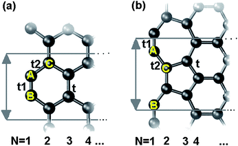 | ||
| Fig. 1 Crystal structure of an infinitely long GNR shows bare ended (a) AGNR and (b) recZGNR with one edge reconstructed unit cells (gray lines) as well as indication width N, atom positions A–C and the corresponding tij. | ||
2. Principles and algorithm
As far as the π and π*orbitals of the C 2pz electrons are concerned, the Hamiltonian matrix elements are | (1) |
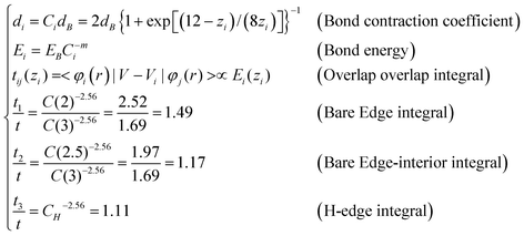
In the conventional TB,11,16,31,32 the tij was set uniformly as well, i.e. t = t1 = t2. According to the BOLS correlation,17 the shorter and stronger bonds between under-coordinated atoms, and the associated exchange and overlap integrals can be formulated as:
 | (2) |
Fig. 2(a) illustrates the integrals enhancement due to the local strain and the associated potential well depression near the edge. According to eqn (2), as the ECN imperfection at the edge, the edge bond will be shortened and strengthened; and the neighbor potential trap to the bonding electron will be closer in real space and deepened in energy space. The tij will be enlarged proportional to the bond energy by C(z)−m. The tij enhancement has actually been verified using density functional theory (DFT) calculations,33 as compared in Fig. 2(b). The BOLS correlation and DFT calculation are in good accordance despite the tiny divergence at the shorter end. It should be noted that limitations exist to DFT in dealing with the low dimensional systems and edge states.
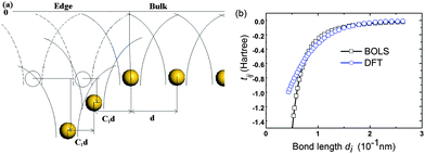 | ||
| Fig. 2 (a) Schematic illustration of the GNR edge bond strain and potential trap. The shorter and stronger edge bonds cause the potential well depression, which enhances the overlap integral according to eqn (2). (b) Correlation between the tij and the bond length d derived from the DFT results33 in comparison to the BOLS prediction. | ||
3. Calculation details
The Hamiltonian matrix for AGNR and reconstructed ZGNR are established. As shown in the Fig. 1(b), the angle between bond A–C and the vertical line is 30.8° determined by the bond contraction at edges according to Table 1. Considering the edge dangling bond, the off-diagonal terms of the Hamiltonian between the dangling bond state and the pz orbital are zero, because they have different symmetries in the z-direction.16 Thus, we only consider the diagonal term ΔD, the dangling bond energy.Both the conventional and the BOLS-modified Hamiltonian matrix were diagonalized to obtain the electronic structures. Meanwhile, the DFT calculations of GNR were performed in CASTEP code.34 The GNR is modeled with a 1 nm vacuum slab in the y and the z direction. The PBE35 functional form in general gradient approximation is chosen with plane wave basis set energy-off: 280eV. The geometry optimization are converged with the tolerances of 10−5 eV/atom energy, the maximum force of 0.03 eV/Å, maximum stress of 0.05 GPa and the maximum displacement of 0.001 Å.
4. Results and discussion
Fig. 3 compares the band structure of an AGNR-11 obtained using (a) the conventional TB, (b) the BOLS-TB, and (c) the DFT, with the dangling bond ΔD as 1 eV compared with the DFT result. A high degeneracy of density of states at E = ±2.7 eV in (a) suggests that the system is unstable. This frustration can be avoided upon the modified TB or DFT in (b) and (c). Since there are 22 unpaired pz electrons 22 double-degenerated bands in the AGNR-11 unit cell, the Fermi level lays at the middle of the EG. The EG opening has also been observed by BOLS-TB (b) and DFT (c), and the dangling bonds provide impurity level closing to the Fermi energy, which does not determine the generation of the band gap.9,36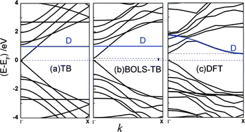 | ||
| Fig. 3 The band structures of the AGNR-11 calculated based on (a) the classical TB, (b) the BOLS-TB method with parameters listed in Table 1 and (c) DFT. The dangling bonds provide impurity states near the Fermi energy, indicated by D. An EG is generated in (b) and (c), and the dangling bond state does not affect the EG generation. | ||
Fig. 4 shows the EG of both bare and H-end AGNR dependence on the ribbon width N. The conventional TB results show that the EG remains to be zero when N = 3p + 2 (p is a natural number); while the modified BOLS-TB results shows the EG opening, being consistent with observations, which is consistent with reported DFT6,12 and experimental observations.10 The edge absorption of H do not affect the EG generation and the expansion trend significantly. Upon Wang and co-worker's work,15 we further explain the causes and reasons of the overlap integral enhancement and determine the quantity of the enhancement not only at edges but also at other sites with under-coordinated atoms such as vacancies and adsorption atoms.
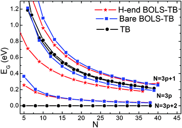 | ||
| Fig. 4 Comparison of the width dependence of the EG in bare and H-end AGNRs shows the absence of EG expansion for the N = 3p + 2 in the classical TB approach, which is untrue. The BOLS-TB results have the same trend to that of DFT.6 | ||
The band structures of recZGNR-8 with bare and H-end calculated using the conventional and the BOLS-TB and DFT method are compared in Fig.5. A very small EG (∼0.1 eV) is generated near Γ point by the BOLS-TB and DFT method. Thus, the EG indeed originates from the edge Quantum trap depression. The dangling bond contributes to an additional state at the Fermi level. The nonbonding electron locally pinned and polarized by the densely trapped bonding electron, which is crucial to explain the extraordinary phenomena of nanomaterial such as local magnetism presence and quantum friction.37
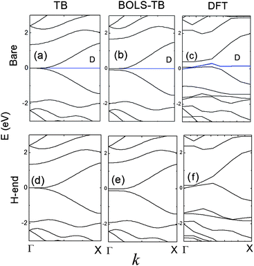 | ||
| Fig. 5 The band structure of a recZGNR-8 obtained by (a) conventional TB with bare end; (b) BOLS-TB with bare end; (c) DFT with bare end; (d) TB with H-end; (e) BOLS-TB with H-end and (f) DFT with H-end. BOLS-TB and DFT method open a gap near Γ point. | ||
5. Conclusion
In conclusion, we have developed a BOLS-TB algorithm to encode the BOLS correlation mechanism for the first time, which has enabled us to clarify the energetic origin of the width dependence of the GNR EG expansion. It has been confirmed that the shorter and stronger bonds between the under-coordinated edge atoms and the associated edge potential trap depression provide the perturbation to the Hamiltonian and initiate the EG opening. The developed approach could be useful and the findings could stimulate more interest in the impact of the shorter and stronger bonds between under-coordinated atoms in low-dimensional systems.References
- C. Q. Sun, S. Y. Fu and Y. G. Nie, J. Chem. Phys. C, 2008, 112(48), 18927–18934 Search PubMed.
- O. Hod, V. Barone, J. E. Peralta and G. E. Scuseria, Nano Lett., 2007, 7(8), 2295–2299 CrossRef CAS.
- L. Brey and H. A. Fertig, Phys. Rev. B: Condens. Matter Mater. Phys., 2006, 73(23), 235411 CrossRef.
- F. M. D. Pellegrino, G. G. N. Angilella and R. Pucci, Phys. Rev. B: Condens. Matter Mater. Phys., 2010, 81(3), 035411 CrossRef.
- S. H. M. Jafri, K. Carva, E. Widenkvist, T. Blom, B. Sanyal, J. Fransson, O. Eriksson, U. Jansson, H. Grennberg, O. Karis, R. A. Quinlan, B. C. Holloway and K. Leifer, J. Phys. D: Appl. Phys., 2010, 43(4), 045404 CrossRef.
- Y. W. Son, M. L. Cohen and S. G. Louie, Phys. Rev. Lett., 2006, 97(21), 216803–216804 CrossRef.
- M. Fujita, K. Wakabayashi, K. Nakada and K. Kusakabe, J. Phys. Soc. Jpn., 1996, 65(7), 1920–1923 CrossRef CAS.
- L. Yang, C.-H. Park, Y.-W. Son, M. L. Cohen and S. G. Louie, Phys. Rev. Lett., 2007, 99(18), 186801 CrossRef.
- V. Barone, O. Hod and G. E. Scuseria, Nano Lett., 2006, 6(12), 2748–2754 CrossRef CAS.
- M. Y. Han, B. Ozyilmaz, Y. Zhang and P. Kim, Phys. Rev. Lett., 2007, 98(20), 206805–206804 CrossRef.
- S. Reich, J. Maultzsch, C. Thomsen and P. Ordejo, Phys. Rev. B: Condens. Matter Mater. Phys., 2002, 66(3), 035412 CrossRef.
- S. S. Yu, Q. B. Wen, W. T. Zheng and Q. Jiang, Mol. Simul., 2008, 34(10), 1085–1090 CrossRef CAS.
- L. Liu and Z. Shen, Appl. Phys. Lett., 2009, 95(25), 252104–252103 CrossRef.
- Y. H. Zhang, K. G. Zhou, K. F. Xie, J. Zeng, H. L. Zhang and Y. Peng, Nanotechnology, 2010, 21(6), 065201 CrossRef.
- Z. F. Wang, Q. Li, H. Zheng, H. Ren, H. Su, Q. W. Shi and J. Chen, Phys. Rev. B: Condens. Matter Mater. Phys., 2007, 75(11), 113406–113404 CrossRef.
- F. Zheng, K.i. Sasaki, R. Saito, W. Duan and B. L. Gu, J. Phys. Soc. Jpn., 2009, 78(7), 074713 CrossRef.
- C. Q. Sun, Prog. Solid State Chem., 2007, 35(1), 1–159 CrossRef CAS.
- M. R. Falvo, G. J. Clary, R. M. Taylor, V. Chi, F. P. Brooks, S. Washburn and R. Superfine, Nature, 1997, 389, 582–584 CrossRef CAS.
- E. W. Wong, P. E. Sheehan and C. M. Lieber, Science, 1997, 277(5334), 1971–1975 CrossRef CAS.
- B. An, S. Fukuyama, K. Yokogawa and M. Yoshimura, Jpn. J. Appl. Phys., 1998, 37, 3809–3811 CrossRef CAS (Part 1, No. 6B).
- J. C. ÇÖ. GiritMeyer, R. Erni, M. D. Rossell, C. Kisielowski, L. Yang, C.-H. Park, M. F. Crommie, M. L. Cohen, S. G. Louie and A. Zettl, Science, 2009, 323, 1705 CrossRef CAS.
- C. Q. Sun, H. L. Bai, B. K. Tay, S. Li and E. Y. Jiang, J. Phys. Chem. B, 2003, 107, 7544–7546 CrossRef CAS.
- C. Q. Sun, Y. Sun and Y. G. Nie, J. Phys. Chem. C, 2009, 113, 16464–16467 CrossRef CAS.
- K.j. Kim, H. Lee, J. H. Choi, Y. S. Youn, J. Choi, H. Lee, T. H. Kang, M. C. Jung, H. J. Shin, H. J. Lee, S. Kim and B. Kim, Adv. Mater., 2008, 20(19), 3589–3591 CrossRef CAS.
- T. Balasubramanian, J. N. Andersen and L. Wallden, Phys. Rev. B: Condens. Matter Mater. Phys., 2001, 64, 205420 CrossRef.
- S. Takabayashi, K. Motomitsu, T. Takahagi, A. Terayama, K. Okamoto and T. Nakatani, J. Appl. Phys., 2007, 101, 103542 CrossRef.
- L. Pauling, J. Am. Chem. Soc., 1947, 69(3), 542–553 CrossRef CAS.
- V. M. Goldschmidt, Ber. Dtsch. Chem. Ges., 1927, 60, 1263–1296 CrossRef.
- X. Zhang, J.-l. Kuo, M. Gu, X. Fan, P. Bai, Q.-G. Song and C. Q. Sun, Nanoscale, 2010, 2, 412–417 RSC.
- P. Koskinen, S. Malola and H. Häkkinen, Phys. Rev. B: Condens. Matter Mater. Phys., 2009, 80, 073401 CrossRef.
- R. Saito, G. Dresselhaus and M. S. Dresselhaus, Physical properties of carbon nanotubes. (Imperial College Press, London, 1998) Search PubMed.
- R. M. Ribeiro, et al. , New J. Phys., 2009, 11(11), 115002 CrossRef.
- D. Porezag, T. Frauenheim, T. Koler, G. Seifert and R. Kaschner, Phys. Rev. B: Condens. Matter, 1995, 51(19), 12947 CrossRef CAS.
- S. J. Clark, M. D. Segall and C. J. Pickard, Z. Kristallogr., 2005, 220(5–6–2005), 567–570 CrossRef CAS.
- J. P. Perdew, K. Burke and M. Ernzerhof, Phys. Rev. Lett., 1996, 77, 3865–3868 CrossRef CAS.
- R. A. Street, Hydrogenated amorphous silicon. (Cambridge University Press, 1991) Search PubMed.
- C. Q. Sun, Y. Sun, Y. Ni, X. Zhang, J. Pan, X.-H. Wang, J. Zhou, L.-T. Li, W. Zheng, S. Yu, L. K. Pan and Z. Sun, J. Phys. Chem. C, 2009, 113(46), 20009–20019 CrossRef.
| This journal is © The Royal Society of Chemistry 2010 |
