Horizontally and vertically aligned helical conjugated polymers: Comprehensive formation mechanisms of helical fibrillar morphologies in orientation-controlled asymmetric reaction fields consisting of chiral nematic liquid crystals†
Taizo
Mori
a,
Mutsumasa
Kyotani
b and
Kazuo
Akagi
*a
aDepartment of Polymer Chemistry, Kyoto University, Kyoto, 615-8510, Japan. E-mail: akagi@fps.polym.kyoto-u.ac.jp
bTsukuba Research Center for Interdisciplinary Materials Science, University of Tsukuba, Ibaraki, 305-8577, Japan
First published on 17th May 2011
Abstract
Orientation-controlled asymmetric reaction fields consisting of chiral nematic liquid crystals (N*-LCs) were comprehensively studied to elucidate the formation mechanisms of horizontally and vertically aligned helical polyacetylenes (H-PAs). The alignment of the N*-LC was controlled by tuning the concentration of a chiral molecule added as a chiral dopant to a parent nematic LC and/or by using a rod-like molecule used as a vertical orientation inducer. It was found that the horizontal N*-LC gives rise to horizontally aligned H-PAs, and the vertical N*-LC consisting of two types of multilayered arrangements provides U- and V-shaped fibrillar morphologies of vertically aligned H-PAs. The observed formation mechanisms are useful for understanding asymmetric polymerisations of helical conjugated polymers prepared in chiral nematic or cholesteric liquid crystal reaction fields.
Introduction
Helical conjugated polymers1 are useful for various applications.2–5 Helical polyacetylene (H-PA) characterised by hierarchical spiral morphology was first synthesised in chiral nematic liquid crystal (N*-LC). Since then, the N*-LC has been used as an asymmetric reaction field to produce chiral conducting polymers.6 The twisted structure of the N*-LC is formed by addition a small amount of an optically active molecule as a chiral dopant to the nematic LC (N-LC).7 Thus, it is feasible to control the chirality and morphology of a polymer by selecting the chirality of the chiral dopant and macroscopically aligning the N*-LC.8The solid state structure and morphology of PA are determined during the polymerisation process.9 The H-PAs hitherto synthesised have a horizontally aligned morphology because the N*-LC used for acetylene polymerisation has a homogeneous (horizontal) alignment. In a previous work,10 the formation mechanism of a horizontally aligned H-PA in a horizontal N*-LC was examined. The helical axis of the horizontal N*-LC is parallel to the substrate on the free surface and perpendicular to the direction of the depth. Thus, the PA fibrils are parallel to the substrate when the H-PA is synthesised in the horizontal N*-LC. The relationships between the H-PA and the N*-LC are as follows: (i) the screw direction of the H-PA fibrils is opposite to the twisted direction of the N*-LC, (ii) the half-helical pitch of the N*-LC is nearly equal to the interdistance between the fibril bundles of the H-PA, and (iii) the helical axis of the H-PA is perpendicular to that of the N*-LC. The formation mechanism of the horizontally aligned H-PA in the horizontal N*-LC is described in Fig. 1.
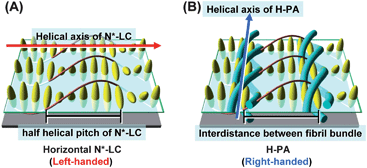 | ||
| Fig. 1 (A) Model structure of the horizontal N*-LC and (B) the formation mechanism of horizontally aligned H-PA in the horizontal N*-LC. The N*-LC molecules and the H-PAs are represented as ellipsoid bodies and blue tubes, respectively. | ||
From the viewpoint of evaluating the physical properties of H-PAs, a macroscopically aligned H-PA is desirable. The macroscopic control of the N*-LC morphology, i.e., the conversion from a poly-domain to a mono-domain structure, needs an external perturbation such as magnetic force, electric force, shear stress, or rubbing.11,12 An alternative method is to use the oriented substrate that has been pre-treated homogeneously (horizontally) or homeotropically (vertically). Among the aligned H-PAs, the vertically aligned H-PA could be useful for evaluating the single-helical bundle of fibrils.
To synthesise the vertically aligned H-PA, the PA fibrils should be perpendicular to the substrate as shown in Fig. 2.13 Because the H-PA grows perpendicular to the helical axis of the N*-LC, to prepare the vertically aligned H-PA, vertical N*-LC is necessary. The vertical N*-LC is prepared by adding not only a vertical orientation inducer but also an axially chiral binaphthyl derivative into the N-LC. The vertical orientation inducer (PCH50)2n (n = 6, 8) has a rod-shaped structure containing two phenylcyclohexyl (PCH) mesogenic moieties linked with a hexa- or octamethylene chain (see Table 1).
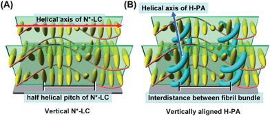 | ||
| Fig. 2 Schematic representation of (A) the vertical N*-LC and (B) the vertically aligned H-PA. The N*-LC molecules and the H-PAs are represented as ellipsoid bodies and blue tubes, respectively. | ||
| Parent LC |

|

|
|

|
|
| Vertical orientation inducer |

|
| Chiral dopant |

|
| System 1 | PCH302: PCH304: (R)- or (S)-(PCH506)4-Binol = 100:100:0.5 |
| System 2 | PCH506: (PCH50)26: (R)- or (S)-(PCH506)4-Binol = 100:5:1.0 |
| System 3 | PCH506: (PCH50)26: (R)- or (S)-(PCH506)4-Binol = 100:5:0.5 |
| System 4 | PCH506: (PCH50)26: (R)- or (S)-(PCH506)4-Binol = 100:5:0.2 |
The macroscopic arrangement of H-PA fibrils is controllable by the N*-LC structure. It is necessary to clarify the formation mechanisms of not only the horizontally aligned H-PA but also the vertically aligned H-PA. The formation mechanism could be useful for understanding other helical conjugated polymers synthesised in the asymmetric reaction fields composed of N*-LCs or cholesteric LCs.
In this work, the orientation of N*-LCs was controlled by tuning the concentrations of both the chiral dopant and the vertical orientation inducer. The horizontally and vertically aligned H-PAs were synthesised in the horizontal and vertical N*-LCs, respectively. The higher-order structures of the horizontal and vertical N*-LCs were evaluated from the observation of polarizing optical micrograph (POM). The morphologies of the H-PA films were examined by scanning electron microscope (SEM). The relationship between the vertical N*-LC and the vertically aligned H-PA was examined, and the formation mechanism for the vertically aligned H-PA in the vertical N*-LC was elucidated.
Experiment section
Preparation of liquid crystals as reaction fields
Table 1 shows the molecular structures of the N-LCs, the vertical orientation inducers and the chiral dopants as well as their mixtures. The N*-LC (system 1) was prepared by adding 1 mol% of (R)-(PCH506)4-Binol as a chiral dopant to the equimolar mixture of N-LCs, 4-(trans-4-n-propylcyclohexyl)ethoxybenzene [PCH302] and 4-(trans-4-n-propylcyclohexyl)butoxybenzene [PCH304].6 It was found that the fibrils of H-PA synthesised in this N*-LC system grew horizontally.10 The N*-LC systems 2, 3 and 4 were prepared by adding 5 mol% of the vertical orientation inducer (PCH50)26 and 0.2∼1 mol% of the chiral dopant (R)- or (S)-(PCH506)4-Binol into the parent LC PCH506.7f,14POM observations of the N*-LCs were carried out under crossed Nicols by using a NIKON ECLIPSE E400 POL polarizing optical microscope equipped with a NIKON COOLPIX 950 digital camera, a Linkam TH-600PM system with temperature controller and an L-600 system with heating and cooling stage. In the POM, all N*-LCs showed a fingerprint texture characteristic of a helical structure. The phase transition temperatures of the N*-LCs were determined with a Perkin-Elmer differential scanning calorimeter (DSC 7) and a TA Instrument Q100 DSC apparatus at a constant heating and cooling rate of 10 °C min−1. The results from the first cooling and the second heating processes were recorded.Acetylene polymerization
The N*-LCs (systems 2 to 4) were used as an acetylene polymerisation solvent for the Ziegler–Natta catalyst consisting of Ti(O-n-Bu)4 and Et3Al. The typical concentration of Ti(O-n-Bu)4 was 50 mmol l−1, and the mole ratio of [Al]/[Ti] was 4. The catalyst solution was aged for 30 min at room temperature. During aging, the N*-LCs containing the catalyst showed no noticeable change in their optical texture and only a slight decrease of the transition temperature by 1 to 3 °C.The catalyst solution was added into a flat-bottom container placed in a Schlenk flask by using a syringe that was warmed beforehand to maintain the fluidity of the highly viscous catalyst solution. The Schlenk flask was connected to a vacuum line via a flexible joint and then degassed. The acetylene polymerisation was carried out by introducing acetylene gas into the catalyst-containing N*-LC. Polymerisation temperature was kept constant at 39 °C by circulating water through an outer flask enveloping the Schlenk flask, to prevent the phase transition to an isotropic phase from the N*-LC phase that is accompanied with exothermic polymerisation. Acetylene gas of six-nine grades was used without further purification. Polymerisation temperature was controlled by immersing the Schlenk flask in a temperature-controlled water bath. The initial acetylene pressure was approximately 40 Torr, and the polymerisation time was 5 min. After polymerisation, the PA film was washed with purified toluene several times and then with 1 N HCl–methanol mixture and THF under argon at room temperature. The film was dried by vacuum pumping on a Teflon sheet and stored in a freezer at −20 °C. The film thickness was in the range of 3 to 6 μm.
Results and discussion
Characterization of N*-LC
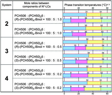
The screw directions of the N*-LCs induced by (R)- or (S)-(PCH506)4-Binol were determined through the miscibility test (contact method).13 The miscibility test is based on the POM observation of the mixing area between the N*-LC and a LC standard with known screw direction. Cholesteryl oleyl carbonate is a left-handed N*-LC (cholesteric LC), and it was used as a LC standard for the miscibility test with the newly prepared LCs. When the screw direction of the N*-LC was the same as that of the LC standard, the mixing area was continuous. Otherwise, this area was discontinuous, giving a Schlieren texture characteristic of the N-LC.As shown in Fig. 3, the miscibility test between system 3 (containing (R)-(PCH506)4-Binol) and cholesteryl oleyl carbonate showed a Schlieren texture in the POM. In contrast, the miscibility test between system 3 (containing (S)-(PCH506)4-Binol) and cholesteryl oleyl carbonate showed no change in optical texture. The results demonstrate that the N*-LCs containing (R)-(PCH506)4-Binol and (S)-(PCH506)4-Binol have right-handed and left-handed helical structures, respectively. Table 2 summarises the phase transition behaviours of the N*-LCs. Systems 2 to 4 showed N* and smectic (S) phases in the cooling process but only N* phase in the heating process. System 2 containing (R)-(PCH506)4-Binol showed the N* phase between 30 and 52 °C and the S phase between ca. 9 and 30 °C in the cooling process. The sufficiently wide temperature region of the N* phase enabled us to perform the acetylene polymerisation in the N*-LC.
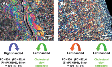 | ||
| Fig. 3 Miscibility tests between (A) system 3 containing (R)-(PCH506)4-Binol and a LC standard (cholesteryl oleyl carbonate) with left-handed screw direction, and (B) system 3 containing (S)-(PCH506)4-Binol and the LC standard. | ||
The helical pitches of the N*-LCs were evaluated with Cano's wedge method,15 and they are summarised in Table 3. The Cano's wedge method is based on the observation of discontinuity lines that appear when an N*-LC is inserted into a cell with a gradient thickness. The helical pitches of systems 2 to 4 varied from 1.2 to 7.0 μm with change in the mole percentage of (R)- or (S)-(PCH506)4-Binol.
| System | N*-LC | H-PA | |||
|---|---|---|---|---|---|
| Mole ratios between components of N*-LCs | Helical pitch (μm) | Distance between fibril bundles (μm) | Diameter of a fibril bundle (μm) | Diameter of a fibril (nm) | |
| 2 | PCH506: (PCH50)26: (R)- or (S)-(PCH506)4-Binol = 100: 5: 1.0 | 1.2 | 0.7 (±0.1) | 0.3 (±0.1) | 130 (±20) |
| 3 | PCH506: (PCH50)26: (R)- or (S)-(PCH506)4-Binol = 100: 5: 0.5 | 2.3 | 1.2 (±0.2) | 0.7 (±0.1) | 200 (±100) |
| 4 | PCH506: (PCH50)26: (R)- or (S)-(PCH506)4-Binol = 100: 5: 0.2 | 7.0 | 3.5 (±0.3) | 0.8 (±0.2) | 200 (±100) |
Model structures of horizontal and vertical N*-LCs
The N*-LC systems 1 and 3 were observed at free surface and lower surface level in the POM. System 1 showed fingerprint texture at the free surface level and Grandjean texture at the lower surface level. When the helical axis of the N*-LC is parallel to the substrate, the fingerprint texture is observed. The helical axis of the N*-LC is perpendicular to the substrate in Grandjean texture. Hence, system 1 is the horizontal N*-LC in which the thin layer of the fingerprint texture is stacked on the Grandjean texture. However, system 3 showed the fingerprint texture at not only the free surface but also the lower surface level. Thus, system 3 is the vertical N*-LC whose helical axis is horizontal to the substrate. The relationship between the texture in POM and the orientation direction of LC molecules to the substrate is also discussed in the Supporting Information.†Fig. 4 shows the POM photographs and the model structures of the horizontal N*-LC (system 1). The model structures depict LC surface layer I, intermediate layer II, and inner layer III. The fingerprint texture is observed in layer I. Thus, the helical axis of the N*-LC is parallel to the substrate in layer II. However, the Grandjean texture is observed in the inner layer III of the horizontal N*-LC. It is suggested that the helical axis of the N*-LC in layer III is perpendicular to the substrate. The intermediate layer II ensures conformity of the surface layer I with the inner layer III in the horizontal N*-LC. As a result, the lower site of the intermediate layer II forms a semicircular column in which a half-helical pitch of the N*-LC is assumed to be a radius.
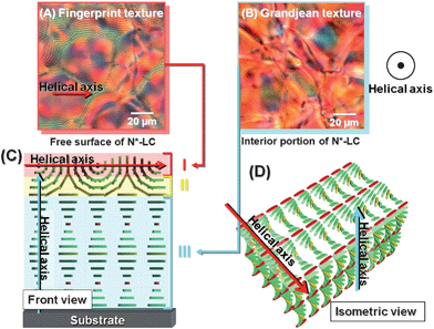 | ||
| Fig. 4 POM photographs of the horizontal N*-LC (system 1). (A) The fingerprint texture observed at the surface of the horizontal N*-LC and (B) the Grandjean texture observed in the inner layer of the horizontal N*-LC. (C) The cross section of model structure of the horizontal N*-LC and (D) the schematic representation of the horizontal N*-LC. The N*-LC molecules are represented as cuboid blocks. | ||
Fig. 5 shows the POM photographs and the model structures of the vertical N*-LC (system 3). The vertical N*-LC shows the fingerprint textures in both layers I and II. Thus, the helical axes of the N*-LC in both layers I and II are parallel to the substrate. The Grandjean texture might be formed in the inner layer III, which means that the helical axis in layer III is perpendicular to the substrate, as in the case of layer III of the horizontal N*-LC. The formation of the Grandjean texture in the inner layer III of system 3 is discussed in more detail by using supplementary data in the Supporting Information.†
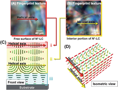 | ||
| Fig. 5 POM photographs of the vertical N*-LC (system 3). (A) The fingerprint texture observed at the surface of the vertical N*-LC and (B) the fingerprint texture observed in the inner layer of the vertical N*-LC. (C) The cross section of model structure of the vertical N*-LC and (D) the schematic representation of the vertical N*-LC. The N*-LC molecules are represented as cuboid blocks. | ||
Morphologies of H-PAs
The H-PA films were synthesised in the N*-LCs that were prepared using a vertical orientation inducer and a chiral dopant. The various morphologies of H-PAs were obtained by tuning the mole ratios of the vertical orientation inducer and chiral dopant added to the N-LCs.The SEM images of the H-PA films synthesised in the N*-LC systems 2 and 3 are shown in Fig. 6. The fibrils of PA synthesised in system 2 are twisted in a one-handed direction but grow parallel to the surface of the film (Fig. 6(A)). When the concentration of the chiral dopant decreases, the fibrils are increasingly twisted and vertically aligned to the substrate (Fig. 6(B)). The helical axis of the fibril bundle is perpendicular to the film surface. The left- and right-handed screw directions of the fibril depend on the chirality of the chiral dopants that have (R)- and (S)-configurations.
![SEM images of H-PAs synthesised in the N*-LC containing (S)-(PCH506)4-Binol. (A) Horizontally aligned H-PAs prepared in system 2 [PCH506: (PCH50)26: (S)-(PCH506)4-Binol = 100: 5: 1.0] and (B) vertically aligned H-PA prepared in system 3 [PCH506: (PCH50)26: (S)-(PCH506)4-Binol = 100: 5: 0.5].](/image/article/2011/SC/c1sc00007a/c1sc00007a-f6.gif) | ||
| Fig. 6 SEM images of H-PAs synthesised in the N*-LC containing (S)-(PCH506)4-Binol. (A) Horizontally aligned H-PAs prepared in system 2 [PCH506: (PCH50)26: (S)-(PCH506)4-Binol = 100: 5: 1.0] and (B) vertically aligned H-PA prepared in system 3 [PCH506: (PCH50)26: (S)-(PCH506)4-Binol = 100: 5: 0.5]. | ||
It should be noted that the horizontal or vertical orientation of the N*-LC crucially depends on (i) the relative concentrations of the vertical orientation inducer and the chiral dopant, (ii) the miscibility of the vertical orientation inducer to the parent N-LC, and (iii) the helical twisting power of the chiral dopant. Namely, the balance in effectiveness of the roles between the vertical orientation inducer and the chiral dopant dominates the macroscopic orientation of the N*-LC and hence the morphological alignment of the H-PA.13d
Fig. 7 shows the SEM image of the H-PA films synthesised in system 4 containing (S)-(PCH506)4-Binol. The fibrils are composed of two types of ridge lines: one line resembles an arch abbreviated as a “ridge line (a)”, and the other line resembles a horn abbreviated as a “ridge line (b)”. It seems that the difference in the ridge line morphology is caused by the surface structure of the N*-LC. The fibrils of the ridge lines (a) and (b) form right-handed curves extending from the inside to the surface of film when the PA film is synthesised in a left-handed N*-LC containing (S)-(PCH506)4-Binol. In contrast, the PA films synthesised in a right-handed N*-LC containing (R)-(PCH506)4-Binol show the ridge lines with left-handed curves. The two types of ridge lines have a rotational symmetry of 90° with respect to each other.
![SEM images of H-PAs synthesised in the vertical N*-LC (system 4) [PCH506: (PCH50)26: (S)-(PCH506)4-Binol = 100: 5: 0.2]. The fibrils are composed of two types of ridge lines: one line resembles an arch abbreviated as a “ridge line (a)”, and the other line resembles a horn abbreviated as a “ridge line (b)”.](/image/article/2011/SC/c1sc00007a/c1sc00007a-f7.gif) | ||
| Fig. 7 SEM images of H-PAs synthesised in the vertical N*-LC (system 4) [PCH506: (PCH50)26: (S)-(PCH506)4-Binol = 100: 5: 0.2]. The fibrils are composed of two types of ridge lines: one line resembles an arch abbreviated as a “ridge line (a)”, and the other line resembles a horn abbreviated as a “ridge line (b)”. | ||
Next, we investigated the structural parameters of the H-PAs, such as the interdistance between the fibril bundles and the diameter of a fibril bundle as well as that of a single fibril, with magnified SEM images. The structural parameters of the H-PAs synthesised in systems 2 to 4 are summarised in Table 3. The interdistance between the fibril bundles of H-PAs decreased with decreasing helical pitch of the N*-LCs. The interdistance between the fibril bundles is equal to the half-helical pitch of the corresponding N*-LC. Although the diameter of the fibril bundles decreased with decreasing helical pitch of the N*-LC, the diameter of a single fibril showed no change, retaining a value of ca. 200 nm.
Formation mechanism of the vertically aligned H-PA in the N*-LC
The relationship between the H-PA and the N*-LC can be described as follows:1. The screw direction of the H-PA fibrils is opposite to the twist direction of N*-LC.
2. The half-helical pitch of N*-LC is nearly equal to the interdistance of the fibril bundles of H-PA.
3. The helical axis of H-PA is parallel to the polymer chain, and the director of the N*-LC is perpendicular to the helical axis of the N*-LC.
It was found that the horizontally aligned H-PAs formed in the horizontal N*-LC (systems 1 and 2), and the vertically aligned H-PAs formed in the vertical N*-LCs (systems 3 and 4). There were two types of ridge lines in the fibril morphology of vertically aligned H-PA (system 4).
It is necessary to consider the inner structures of the N*-LCs to differentiate between the horizontally and vertically aligned H-PAs. Fig. 8 shows the formation mechanism of horizontally aligned H-PA in the horizontal N*-LC. In the horizontal N*-LC, it is unlikely that PA fibrils grow along the director where the LC molecules are perpendicular to the substrates because there is not sufficient space for PA fibrils to grow up. Therefore, the H-PAs (shown as blue ribbons in the figure) are assumed to grow along the N*-LC molecules (red rods in the figure) horizontal to the substrate.
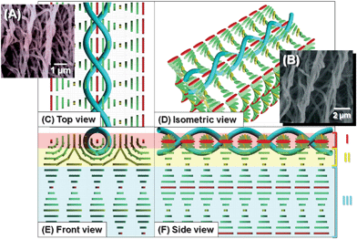 | ||
| Fig. 8 SEM images and formation mechanism of the horizontally aligned H-PA in the horizontal N*-LC. (A), (B) SEM image of H-PAs synthesised in the horizontal N*-LC. Formation mechanism of the horizontally aligned H-PA in the horizontal N*-LC, showing (C) top, (D) isometric, (E) front and (F) side views. The N*-LC molecules and the H-PAs are represented as cuboid blocks and blue tubes, respectively. | ||
Fig. 9 and 10 shows two types of formation mechanisms of H-PAs in the vertical N*-LCs. The vertical N*-LC has a thicker layer fingerprint texture, and the PA fibrils can grow perpendicular to the substrate. When the PA fibrils grow centring on the director where the LC molecules are parallel to the substrate, the fibril morphology shows the ridge line (a) like an inverted U-shape (Fig. 9). The fibril morphology shows the ridge line (b) like an inverted V-shape if the fibrils grow centred on the director where the LC molecules are perpendicular to the substrate (Fig. 10). Thus, there could be two types formation mechanisms of the vertically aligned H-PA synthesised in the vertical N*-LC. In the case of right-handed N*-LC, the inverted U- and V- shaped fibrils show left-handed curves and have rotational symmetries of 90° with respect to each other. In both mechanisms, the interdistance of the fibril bundles of H-PA is equal to the half-helical pitch of the N*-LC, and the helical axis of PA is perpendicular to that of the N*-LC.
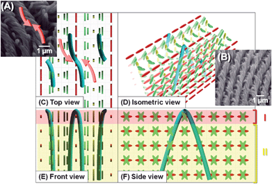 | ||
| Fig. 9 SEM images and formation mechanism of the vertically aligned H-PA (inverted U-shape fibrils) in the vertical N*-LC. (A), (B) SEM images of H-PA fibrils of the ridge line synthesised in the vertical N*-LC. Formation mechanism of the horizontally aligned H-PA in the horizontal N*-LC, showing (C) top, (D) isometric, (E) front and (F) side views. The N*-LC molecules and the H-PAs are represented as cuboid blocks and blue tubes, respectively. The fibril morphology shows the ridge line like an inverted U-shape. | ||
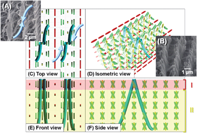 | ||
| Fig. 10 SEM images and formation mechanism of the vertically aligned H-PA (inverted V-shape fibrils) in the vertical N*-LC. (A), (B) SEM images of H-PA fibrils of the ridge line synthesised in the vertical N*-LC. Formation mechanism of the horizontally aligned H-PA in the horizontal N*-LC, showing (C) top, (D) isometric, (E) front and (F) side views. The N*-LC molecules and the H-PAs are represented as cuboid blocks and blue tubes, respectively. The fibril morphology shows the ridge line like an inverted V-shape. | ||
Lastly it is useful to remark an overall interfacial acetylene polymerization in the N*-LC. When discussing the formation mechanism of the H-PA in the N*-LC, one has to consider that the acetylene polymerization occurs interfacially between the gas and liquid phases, and that the PA chains grow along the LC molecules. The latter has already been revealed by the external force-oriented LC reaction field17,18 where the aligned LCs form so-called “one-directionally lined guardrails” and the PA chains are only allowed to grow along and between the guardrails.
In the N*-LC, (i) the PA chain grows along the twisted LC molecules, particularly around the LC ones horizontally placed to the substrate, to give a helical chain. (ii) The neighboring helical chains spontaneously form a helical fibril through van der Waals interaction. (iii) Furthermore, the neighboring helical fibrils are gathered through van der Waals forces to produce a bundle of fibrils with helically twisted structure. (iv) Similar growths of helical PA chains, fibrils, and bundle of fibrils should occur simultaneously around the horizontally aligned LC molecules which are separated by a half helical pitch of the N*-LC, and (v) hence the bundles of fibrils are separated by a half helical pitch the N*-LC. (vi) When the N*-LC molecules exhibit a spiral or aligned structure, the bundle of fibrils also forms spiral or aligned morphology. The helical axes of N*-LC and H-PA are orthogonal to each other, irrespective of the structure of the N*-LC.
It is important to emphasize that in the right-handed N*-LC, for instance, the H-PA chain grows from the catalytic species in a left-handed manner. The H-PA chains with a screw direction opposite to that of N*-LC smoothly propagate along the LC molecules. When the H-PA chains with the same screw direction as that of the N*-LC encounter the LC molecules, a sterically unfavourable polymerization results. Thus, the acetylene polymerization mechanism in the N*-LC is called “bevel type screw arrangement” mechanism between the forming PA fibrils and the LC twist.10 The interfacial polymerization in the N*-LC on the basis of the “bevel type screw arrangement” mechanism should provide insights into construction of helical fibrils under asymmetric reaction field from molecular levels.
Conclusions
A comprehensive study on the formation mechanisms of horizontally and vertically aligned H-PAs having helical fibrillar morphologies was carried out. The horizontally and vertically aligned H-PAs were synthesised in orientation-controlled asymmetric reaction fields consisting of N*-LCs. The alignment of the N*-LC was controlled by tuning the concentration of a chiral molecule added as a chiral dopant to a parent nematic LC and/or by using a rod-like molecule used as a vertical orientation inducer. It was found that the interfacially homogeneous N*-LC gives rise to the horizontally aligned H-PAs and that the vertically aligned N*-LC consists of two types of multilayered arrangements and, hence, provides U- and V-shaped fibrillar morphologies of vertically aligned H-PAs. The observed formation mechanisms are useful for the general understanding of asymmetric polymerisations of helical conjugated polymers prepared in chiral nematic or cholesteric liquid crystal reaction fields.16Acknowledgements
The authors acknowledge Dr Ken Ishikawa and Prof. Hideo Takezoe, Tokyo Institute of Technology for measurements of reflection POMs. This work was supported bay a Grant-in-Aid for Science Research (S) (No. 20225007) from the Ministry of Education, Culture, Sports, Science and Technology, Japan.Notes and references
- T. Iwasaki and H. Nishide, Curr. Org. Chem., 2005, 9, 1665–1684 CrossRef CAS.
- (a) H. J. Lee, Z. X. Jin, A. N. Aleshin, J. Y. Lee, M. J. Goh, K. Akagi, Y. S. Kim, D. W. Kim and Y. W. Park, J. Am. Chem. Soc., 2004, 126, 16722–16723 CrossRef CAS; (b) A. N. Aleshin, H. J. Lee, Y. W. Park and K. Akagi, Phys. Rev. Lett., 2004, 93, 196601 CrossRef CAS; (c) A. N. Aleshin, H. J. Lee, K. Akagi and Y. W. Park, Microelectron. Eng., 2005, 81, 420–427 CrossRef CAS; (d) A. N. Aleshin, H. J. Lee, S. H. Jhang, H. S. Kim, K. Akagi and Y. W. Park, Phys. Rev. B: Condens. Matter Mater. Phys., 2005, 72, 153202 CrossRef; (e) S. W. Lee, B. Kim, D. S. Lee, H. J. Lee, J. G. Park, S. J. Ahn, E. E. B. Campbell and Y. W. Park, Nanotechnology, 2006, 17, 992–996 CrossRef CAS; (f) M. Ofuji, Y. Takano, Y. Houkawa, Y. Takanishi, K. Ishikawa, H. Takezoe, T. Mori, M. Goh, S. Guo and K. Akagi, Jpn. J. Appl. Phys., 2006, 45, 1710–1713 CrossRef CAS.
- (a) B. M. W. Langeveld-Voss, R. A. J. Janssen, M. P. T. Christiaans, S. C. J. Meskers, H. P. J. M. Dekkers and E. W. Meijer, J. Am. Chem. Soc., 1996, 118, 4908–4909 CrossRef CAS; (b) E. Peeters, M. P. T. Christiaans, R. A. J. Janssen, H. F. M. Schoo, H. P. J. M. Dekkers and E. W. Meijer, J. Am. Chem. Soc., 1997, 119, 9909–9910 CrossRef CAS.
- (a) E. Yashima, T. Matsushima and Y. Okamoto, J. Am. Chem. Soc., 1995, 117, 11596–115967 CrossRef CAS; (b) E. Yashima, T. Matsushita and Y. Okamoto, J. Am. Chem. Soc., 1997, 119, 6345–6359 CrossRef CAS; (c) E. Yashima, K. Maeda and Y. Okamoto, Nature, 1999, 399, 449–451 CrossRef CAS; (d) T. Nakano and Y. Okamoto, Chem. Rev., 2001, 101, 4013–4038 CrossRef CAS; (e) C. Yamamoto and Y. Okamoto, Bull. Chem. Soc. Jpn., 2004, 77, 227–257 CrossRef CAS; (f) K. Maeda, K. Morino, Y. Okamoto, T. Sato and E. Yashima, J. Am. Chem. Soc., 2004, 126, 4329–4242 CrossRef CAS; (g) J. Liu, J. W. Y. Lam and B. Z. Tang, Chem. Rev., 2009, 109, 5799 CrossRef CAS; (h) E. Yashima, K. Maeda, H. Iida, Y. Furusho and K. Nagai, Chem. Rev., 2009, 109, 6102 CrossRef CAS.
- (a) P. A. Bross, U. Schoberl and J. Daub, Adv. Mater., 1991, 3, 198–200 CrossRef CAS; (b) W. Li and H. L. Wang, J. Am. Chem. Soc., 2004, 126, 2278–2279 CrossRef CAS; (c) R. Iwaura, F. J. M. Hoeben, M. Masuda, A. P. H. J. Schenning, E. W. Meijer and T. Shimizu, J. Am. Chem. Soc., 2006, 128, 13298–13304 CrossRef CAS.
- (a) K. Akagi, G. Piao, S. Kaneko, K. Sakamaki, H. Shirakawa and M. Kyotani, Science, 1998, 282, 1683–1686 CrossRef CAS; (b) K. Akagi, G. Piao, S. Kaneko, I. Higuchi, H. Shirakawa and M. Kyotani, Synth. Met., 1999, 102, 1406–1409 CrossRef CAS; (c) K. Akagi, I. Higuchi, G. Piao, H. Shirakawa and M. Kyotani, Mol. Cryst. Liq. Cryst., 1999, 332, 463–470; (d) K. Akagi, S. Guo, T. Mori, M. Goh, G. Piao and M. Kyotani, J. Am. Chem. Soc., 2005, 127, 14647–14654 CrossRef CAS; (e) M. J. Goh, M. Kyotani and K. Akagi, Curr. Appl. Phys., 2006, 6, 948–951 CrossRef; (f) K. Akagi, Polym. Int., 2007, 56, 1192–1199 CrossRef CAS; (g) M. Goh, T. Matsushita, M. Kyotani and K. Akagi, Macromolecules, 2007, 40, 4762–4771 CrossRef CAS; (h) K. Akagi, In: Handbook of Conducting Polymers, Conjugated Polymers. 3rd ed.: T. A. Skotheim, J. R Reynolds, ed.: CRC Press: New York, 2007: pp 3–14 Search PubMed; (i) M. Goh, M. Kyotani and K. Akagi, J. Am. Chem. Soc., 2007, 129, 8519–8527 CrossRef CAS; (j) T. Mori, M. Kyotani and K. Akagi, Macromolecules, 2008, 41, 607–613 CrossRef CAS; (k) M. Kyotani, S. Matsushita, T. Nagai, Y. Matsui, M. Shimomura, A. Kaito and K. Akagi, J. Am. Chem. Soc., 2008, 130, 10880–10881 CrossRef CAS; (l) M. Goh, T. Matsushita, H. Satake, M. Kyotani and K. Akagi, Macromolecules, 2010, 43, 5943–5948 CrossRef CAS; (m) K. Akagi, Chem. Rev., 2009, 109, 5354–5401 CrossRef CAS; (n) M. Goh, S. Matsushita and K. Akagi, Chem. Soc. Rev., 2010, 39, 2466–2476 RSC.
- (a) G. Heppke, D. Lötzsch, F. Z. Oestreicher and A. Naturforsch, Phys. Sci., 1986, 41a, 1214–1218 Search PubMed; (b) K. Kanazawa, I. Higuchi and K. Akagi, Mol. Cryst. Liq. Cryst., 2001, 364, 825–834 CrossRef CAS; (c) J. Rokunohe and A. Yoshizawa, J. Mater. Chem., 2005, 15, 275–279 RSC.
- (a) G. Gottarelli, P. Mariani, G. P. Spada, B. Samori, A. Forni, G. Solladie and M. Hibert, Tetrahedron, 1983, 39, 1337–1344 CrossRef CAS; (b) H. G. Kuball and T. Hofer, in: Chirality in Liquid Crystals (Partially Ordered Systems): H. S. Kitzerow, C. Bah, ed.: Springer: New York, 2001 Search PubMed.
- For instance: (a) H. Shirakawa, T. Masuda, T. Takeda, In: The Chemistry of Triple-Bonded Functional Groups, Suppl. C2: S. Patai, Ed.: Wiley: Chichester, U.K., 1994; Vol. 2, Chap. 17, p 945 Search PubMed; (b) K. Akagi, H. Shirakawa, In: The Polymeric Materials Encyclopedia. Synthesis, Properties and Applications. J. C. Salamone, Ed.: CRC Press, 1996: Vol. 5, p 3669 Search PubMed; (c) K. Akagi, H. Shirakawa, In: Electrical and Optical Polymer Systems: Fundamentals, Methods, and Applications. D. L. Wise, et al., ed.: Marcel Dekker, 1998: Chap. 28, p 983 Search PubMed; (d) J. W. Y. Lam and B. Z. Tang, Acc. Chem. Res., 2005, 38, 745–54 CrossRef CAS.
- T. Mori, M. Kyotani and K. Akagi, Macromolecules, 2010, 42, 8363–8372 CrossRef.
- (a) K. Araya, A. Mukoh, T. Narahara and H. Shirakawa, Chem. Lett., 1984, 1141–1142 CAS; (b) K. Akagi, H. Shirakawa, K. Araya, A. Mukoh and T. Narahara, Polym. J., 1987, 19, 185–189 CrossRef CAS; (c) K. Akagi, S. Katayama, H. Shirakawa, K. Araya, A. Mukoh and T. Narahara, Synth. Met., 1987, 17, 241–246 CAS; (d) K. Akagi, S. Katayama, M. Ito, H. Shirakawa and K. Araya, Synth. Met., 1989, 28, D51–D56 CrossRef CAS; (e) M. Sinclair, D. Moses, K. Akagi and A. J. Heeger, Phys. Rev. B, 1988, 38, 10724–10733 CrossRef CAS.
- (a) A. Montaner, M. Rolland, J. L. Sauvajol, M. Galtier, R. Almairac and J. L. Ribet, Polymer, 1988, 29, 1101–1104 CrossRef CAS; (b) N. Coustel, N. Foxonet, J. L. Ribet, P. Bernier and J. E. Fischer, Macromolecules, 1991, 24, 5867–5873 CrossRef CAS.
- (a) G. Piao, T. Otaka, T. Sato, K. Akagi and M. Kyotani, Mol. Cryst. Liq. Cryst., 2001, 365, 117–127 CAS; (b) H. Shirakawa, T. Otaka, G. Piao, K. Akagi and M. Kyotani, Synth. Met., 2001, 117, 1–8 CrossRef CAS; (c) T. Mori, T. Sato, M. Kyotani and K. Akagi, Synth. Met., 2003, 135, 83–84 CrossRef; (d) T. Mori, T. Sato, M. Kyotani and K. Akagi, Macromolecules, 2009, 42, 1817–1823 CrossRef CAS.
- (a) G. Heppke and F. Oestetreicher, Mol. Cryst. Liq. Cryst., 1978, 41, 245–249 CAS; (b) T. Uchida, T. Inukai, In: Liquid Crystal-Fundamentals. K. Okano, S. Kobayashi, ed.: Baifukan: Tokyo, 1985: p 205–231 Search PubMed.
- (a) F. C. R. Grandjean, Hebd. Seances Acad. Sci., 1921, 172, 71 Search PubMed; (b) R. Cano, Bull. Soc. Fr. Mineral., 1968, 91, 20–27 Search PubMed; (c) G. Gottarelli, B. Samori, C. Stremmenos and G. Torre, Tetrahedron, 1981, 37, 395–399 CrossRef CAS.
- (a) H. Goto and K. Akagi, Macromol. Rapid Commun., 2004, 25, 1482–1486 CrossRef CAS; (b) H. Goto and K. Akagi, Macromolecules, 2005, 38, 1091–1098 CrossRef CAS; (c) H. Goto, N. Nomura and K. Akagi, J. Polym. Sci., Part A: Polym. Chem., 2005, 43, 4298–4302 CrossRef CAS; (d) H. Hayasaka, K. Tamura and K. Akagi, Macromolecules, 2008, 41, 2341–2346 CrossRef CAS.
- (a) K. Araya, A. Mukoh, T. Narahara and H. Shirakawa, Synth. Met., 1986, 14, 199–206 CrossRef CAS; (b) K. Akagi, H. Shirakawa, K. Araya, A. Mukoh and T. Narahara, Polym. J., 1987, 19, 185–1889 CrossRef CAS; (c) K. Akagi, S. Katayama, H. Shirakawa, K. Araya, A. Mukoh and T. Narahara, Synth. Met., 1987, 17, 241–246 CAS; (d) K. Akagi, S. Katayama, M. Ito, H. Shirakawa and K. Araya, Synth. Met., 1989, 28, 51–56 CrossRef.
- (a) A. Montaner, M. Rolland, J. L. Sauvajol, M. Galtier, R. Almairac and J. L. Ribet, Polymer, 1988, 29, 1101–1104 CrossRef CAS; (b) N. Coustel, N. Foxonet, J. L. Ribet, P. Bernier and J. E. Fischer, Macromolecules, 1991, 24, 5867–5873 CrossRef CAS.
Footnote |
| † Electronic supplementary information (ESI) available. See DOI: 10.1039/c1sc00007a |
| This journal is © The Royal Society of Chemistry 2011 |

 .
.