Solar cells with one-day energy payback for the factories of the future
Nieves
Espinosa
a,
Markus
Hösel
b,
Dechan
Angmo
b and
Frederik C.
Krebs
*b
aDepartamento de Electrónica, Tecnología de Computadoras y Proyectos, Universidad Politécnica de Cartagena, Campus Muralla del Mar. C/Doctor Fleming s/n, 30202, Cartagena, Spain
bRisø National Laboratory for Sustainable Energy, Technical University of Denmark, Frederiksborgvej 399, DK-4000, Roskilde, Denmark. E-mail: frkr@risoe.dtu.dk
First published on 2nd December 2011
Abstract
Scalability is a requirement before any new energy source can be expected to house a possible solution to the challenge that mankind’s increasing energy demand presents. No renewable energy source is as abundant as the Sun and yet efficient and low-cost conversion of solar energy still has not been developed. We approach the challenge by firstly taking a technology that efficiently addresses the need for daily production of 1 GWp on a global level, which does not employ elements with critically low abundance and has a low thermal budget. We then applied life cycle assessment methodologies to direct research and developed such technology in the form of a polymer solar cell that presents a significant improvement in energy payback time (EPBT) and found that very short energy payback times on the order of one day are possible, thus potentially presenting a solution to the current energy gap of >14 TW by year 2050.
Broader contextCritical for the success of renewable energy technologes is the time it takes for a given technology to earn back the energy invested in its making and constitution. This is known as the energy payback time (EPBT) and for the most successful and mature renewable energy sources such as wind and hydro power the EPBT is in the range of 3–6 months. For the solar technologies the EPBT is significantly longer and even for mature photovoltaic (PV) technologies such as crystalline silicon the EPBT is in the range of 1–2 years and unlikely to decrease significantly due to very high processing temperatures and materials usage. The polymer solar cell is a very recent PV technology that already rivals existing PV technologies in terms of EPBT even if they currently present a shorter operational lifetime. Due to the very low processing temperature and a thin outline we demonstrate that it is possible to achieve exceptionally low EPBT values in the range of one day pending the realizations of the projected performance for the technology and through the use of solar thermal and solar electric energy for processing. We demonstrate that the technology in its current form outperforms existing PV. |
1 Introduction
The projected increase in energy demand between now (year 2011) and the year 2050 is on the order of 1 GW a day. This “one-gigawatt-a-day” challenge is equivalent to the building of an average nuclear power plant a day for the next ∼40 years (globally). There is currently no available technology that can address this while the energy sources are fortunately available. Several of the known renewable energy sources (wind, biofuel, hydro, solar) are truly renewable in the sense that their source is ultimately the sun. Except for solar energies (thermal and electric) all those sources are derived from the sun through secondary processes and thus the technical potential for extraction is inherently lower and therefore direct usage of solar energy is of great interest. The projections on world energy demand to 2050 will require an increase in energy production capacity as described above, but they also imply a growing uncertainty concerning the energy supply. World electricity demand in particular, is expected to grow more sharply than any other final form of energy. Since “renewables” are low-carbon technologies, they can tackle climate change targets and play a central role in reducing this uncertainty.Today renewable energy sources account for almost 20% of the total electricity production. That share has changed only marginally since 2000. In 2008, 85% of the electricity from renewable sources came from hydropower, and the share of other renewable energy sources combined is around 2%.1 Hydropower as an electricity source has been leading over the past century to electricity production, but wind and photovoltaics (PV) have been steeply increasing in the last decade. Solar cells provide just a tiny slice of the world's electricity, but thanks to technology improvements and government policies, the total PV capacity has multiplied by a factor of 27 at a rate of 40% since 2000 and now reaches a total installed capacity of 39.5 GW. Solar thermal energy conversion is presently accessible in high yield but is in efficient use in the form of heat and is not as easily distributed as solar electric energy, which thus far has been quite limited in use. There are solar electric energy conversion systems in existence that convert above 40% of the incoming solar energy into electricity and this clearly demonstrates the potential to directly convert sunlight into electrical energy with great efficiency. In the next 50 years, according to a projection by the International Energy Agency, solar generators are likely to produce the majority of the world's power by 2060.2
While the conversion efficiency is often used as the metric to evaluate the performance and potential usefulness of a technology or system, it does not take into account the scale of the problem at hand and the potential unavailability of elements or components, nor does it take into account if it is possible to create the required energy producing unit in a given amount of time and whether the energy producing unit is capable of delivering back the energy spent creating it in a reasonable time. To address this life cycle assessments of the different technologies is a very useful tool and ideally reveals that a given technology quickly pays back the energy spent making it and operates for significantly longer. Table 1 lists a selection of renewable energy technologies and their energy returns or energy payback times (EPBT).
| Energy source/Technology | EPBT (years) | Source | |
|---|---|---|---|
| Wind | On land | 0.26 | 3 |
| Offshore | 0.39 | ||
| PV technologies | Silicon mono- and polycrystalline | 1.65–4.12 | 4,5 |
| Amorphous silicon | 1.13 | 6 | |
| GaAs PV | 2.36–5 | 7,8 | |
| GaInP/GaAs | 2.14–4.6 | ||
| CdTe | 0.73–1.61 | 8,7 | |
| CIS | 2.02–2.26 | 5,7 | |
| OPV | 0.2–4 | 9–11 | |
| Hydropower | 0.5 | 12,13 | |
| Geothermal | 0.54 | 13 | |
| Biomass | Gasification | Below 5 years | 14 |
| Biomass combustion | 5–10 | 15 | |
When examining the above renewable energy sources, the best performers as mature technologies have energy payback times of hundreds of days to years; however the current manufacturing speed is not easily envisaged as even approaching a daily production capacity of 1 GWp a day.
There is a general agreement that the photovoltaic (PV) technology is an ideal way to harvest solar energy as it is silent, has no moving parts and in principle requires little or no maintenance once installed. All existing PV technologies however suffer from several drawbacks: most notably their relatively high cost, large thermal budgets and relatively slow manufacture. Even if some of the PV technologies do provide competitive electricity production costs they still present a slow learning curve and energy payback times on the order of years. There are currently only two PV technologies that do not employ rare elements that technically prevents them from realistically addressing the 1-gigawatt-a-day challenge. Those are the silicon based PV and the polymer or organic solar cells.
The polymer solar cell in particular has the advantage over all PV technologies that the possible manufacturing speed is very high and the thermal budget is low as no high temperatures are needed. The polymer solar cell also has drawbacks and it can by no means be viewed as a mature technology. Especially, the operational lifetimes and power conversion efficiencies have been viewed by many as prohibitively short and low. The polymer solar cell has however consistently improved in both aspects, and now presents operational lifetimes of several years and laboratory efficiencies approaching 10%. The EC have in a report (A vision for photovoltaic technology – Report by the Photovoltaic Technology Research Advisory Council PV-TRAC, European Commission, 2005) projected operational lifetimes for more than 10 years and power conversion efficiencies of more than 10% by year 2020 (the projected attainable values are in the range of 12–17%). The most distinguishing feature of the polymer solar cell is the possibility to print or coat the device directly onto a thin flexible carrier substrate using roll-to-roll coating and printing methods which enable simple handling and fast processing. While the use of flexible substrates is what enables fast and low cost processing, flexibility is possibly not needed in the final product.
Justification of polymer solar cell usage in the available form (outside the laboratory) has been questioned due to the relatively low performance characteristics. It is however not uncommon for PV technologies to exhibit a lower performance in their manufactured form as compared to the laboratory records (i.e. mass produced silicon PV presents a power conversion efficiency of 65% compared to the laboratory record). Polymer solar cells prepared in large numbers by roll-to-roll methods thus present power conversion efficiencies in the range of 2–3% on the active area (on average). To overcome the criticism several challenging developments have been highlighted as needed before OPV can become a success and the most focus has been on improving the power conversion efficiency but also the operational lifetime. Especially the latter has recently been given much attention due to the fact that a mediocre solar cell with a long operational lifetime easily outperforms a high performing (with respect to efficiency) but short lived solar cell over time when considering the total energy that the solar cell can potentially deliver during its service life.
1.1 Organic solar cells
A wide range of materials is used in PV, from the traditional multicrystalline silicon wafers to thin-film silicon solar cells and devices composed of plastic or organic semiconductors. Both laboratory and commercial efficiencies for all kinds of solar cells have risen steadily in recent years, indicating that research efforts could further enhance the performance of solar cells. Unlike the conventional PV technologies, OPV has the lowest energy embedded in the cells, as well as the poorest performance. However, whereas the drop in efficiency when going from silicon to OPV is a factor of 10–20 (on the module level) the drop in equivalent primary energy (EPE) drops by a factor of >150.4Typical OPV structures comprise a series of layers, one on top of another. As shown in the image (Fig. 1), first a transparent electrode acting as anode or cathode is set down on a transparent base. Then, a selective conductor layer can be deposited on top, followed by the active layer, where the light harvesting and photovoltaic effect take place. Another selective conductor is usually needed for guiding the holes/electrons to the opposite electrode (the last deposited layer).
 | ||
| Fig. 1 Typical 5-layer OPV structure showing the front trough substrate (left image) and back illumination (right image). Note that in the latter case, the electrode size is reduced in order for the light to enter through the back. ET stands for electron transport, and HT for hole transport. | ||
There exist two basic configurations of OPV cells. The normal device geometry comprises four layers on the substrate (Fig. 1 left, without ET layer) whereas the inverted device type has five layers to enable selective transport of electrons to i.e. ITO and holes to the metal electrode (Fig. 1 both images). The entry of the light to the active layer depends on the position of the transparent electrode (front or back).
The need for a transparent and highly conductive layer as an electrode in printed electronics was created in the mid-1970s. ITO, having both characteristics when deposited by vacuum sputtering tools first on glass and now on flexible substrates, was commercially developed and grew rapidly. But indium is a rare and scarce element. In order to remedy the problem of indium scarcity (indium is the main component of ITO) the routes towards ITO-free solar cells should include the use of a solution processable transparent polymer electrode instead of vacuum processed ITO.
A number of alternatives have been recently employed in small laboratory devices, including: carbon nanotubes,16–18graphene,19–21silver nanowires (AgNW),22 highly conducting polymers and metal grid electrodes23–28 as the firstly processed electrode being transparent or semi-transparent. A second approach involves a non-transparent layer as the firstly processed layer. An example of this is the use of evaporated aluminium–chromium27,28 as the firstly processed non-transparent electrode, the semitransparent electrode having been processed lastly and being comprised of a doped polythiophene derivative (PEDOT:PSS) in combination with a metallic current collecting grid. Despite the advantage of high conductivity, the non-transparent nature of current collecting grids incurs losses in active area. None of the transparent electrode materials (alternative to ITO) available today provide both high transparency and high electrical conductivity simultaneously. More current-collector geometries (such as hexagonal, parallel line or interdigitated) on the scale of <1 mm should be studied.
Most of the rear contacts employed today within the field of photovoltaics are based on silver while there have been efforts in replacing silver with aluminium or copper.
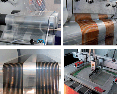 | ||
| Fig. 2 Photographs of ITO-free polymer solar cells prepared entirely using roll-to-roll processing from solution. The width of the web is 305 mm and two modules comprising 16 serially connected cells are coated and printed simultaneously. The coated semi-transparent front electrode is cured (top left). The active layer is slot-die-coated on top of the transparent front electrode coated with zinc oxide, seen as the orange brown colour of the wet film (top right). The semi-transparent hole transport layer is coated and dried on top of the stack (bottom left). Finally, a silver or carbon based back electrode is screen printed to complete the modules (bottom right, here shown as silver). | ||
Silicon technologies could also face the “1 GWp a day” challenge within the next decade but this would require a vast investment both in terms of energy and cost. The upscaling needed before one is able to produce 365 GWp a year would require an energy input of around 1.37 × 10¹⁰GJ and an investment of 641 billion euros. In comparison, 10 times less energy and 3 times lower capital investment would be needed with a similar OPV installation (Table 2).
| COSTS | Unit | Silicon PV | OPV (10%) | OPV (1%) |
|---|---|---|---|---|
| Monetary investment | ||||
| Annual capacity production | GWp | 365 | 365 | 365 |
| Cost per Wp produced | € | 1.76 | 0.63 | 6.32 |
| Cost 1 GWp/day plant | Billion € | 641.22 | 230.53 | 2305.34 |
| Energy investment | ||||
| Equivalent primary energy | MJ W−1p | 37.43 | 0.4511 | 4.51 |
| EPE for production 1 GWp/day | GJ | 1.37E + 10 | 1.65E + 08 | 1.65E + 09 |
1.2 The life cycle analysis as a research tool
Life cycle assessments/analyses (LCA) are an excellent tool to point out weaknesses and strengths of a process providing useful feedback for development. A LCA characterizes and quantifies the total environmental burdens of a product or system, from raw materials extraction to end-of-life management. Several LCAs of energy technologies have been carried out in the past few years as shown in Table 1, however with regard to the photovoltaic field, these studies revealed that PV technologies always consume less energy during their manufacturing than the energy generated over their entire life cycle. The EPBT has been thoroughly investigated for all PV technologies already on the market, and ranges between 4.12 and 0.73 years.6,5,36 For mono-Si EPBTs from 4.12 to 2.68 years can be found, depending on power conversion efficiencies (11.8 or 14%), for commercial modules; polycrystalline-Si has an EPBT of 2 years for 13% efficiency;36,37 amorphous-Si, 1.13 years for 7% efficiency;38CIS, 2.26–2.2 years for 8.9–11% efficiency,5,7 and CdTe, 1.61–0.73 years for 11–13%;7 and OPV from roll to roll processing, 0.79 to 2.02 years for 5 to 2% efficiency.9,11 Particularly, polymer solar cells have been analysed and have proved that the embodied energy in the cells is notably lower, accounting for around 50–80% less than in silicon and thin film-based PV technologies. One of the first LCA studies on polymer solar cell preparation on a laboratory scale10 showed that two-thirds of the energy embedded was devoted to maintaining an oxygen free nitrogen atmosphere in a glove box.When analysing polymer solar cells prepared according to a well described process (known as ProcessOne39) and by using as input all the processing parameters it was found that energy payback times ranging from 1.35 to 2.02 years were possible (corresponding to 3 and 2% efficiency, respectively).11
Before this first thorough life cycle analysis of the roll-to-roll process for manufacturing OPV cells,11 no precise information was available of the parameters likely to affect the future scale up of manufacturing. This first study concluded that 90% of the total energy was embedded in the transparent conductor.
The large requirements for both energy and monetary cost in the ITO sputtering were clearly identified as dominating materials cost,35 and as an imbalance in the inventory (see ProcessOne in Fig. 11). The assumptions during computing of the embedded energy in the ITO layer were made by extrapolating the sputtering requirements on a laboratory scale—on the order of dozens of square centimetres—to a medium-scale production, in the range of several square meters. And the result was around 170–235 MJEPE m−2 for the typical ITO thicknesses (90 to 180 nm). New sputtering tools using R2R processes are being launched on the market, and while they promise lower embedded energy in the range of 30–50 MJEPE m−2 this should be verified by actual manufacture while accounting for all energy inputs.
Nevertheless, this process would still represent a large share of the embedded energy. Attempts to solve this by replacing indium with abundant and less-demanding energy electrode materials have been investigated. The use of aluminium-chromium composite electrodes was analysed by the LCA methodology,40 showing an even poorer balance in agreement with the intensive energy fabrication of the electrode. The most pertinent question that came up was what the developments should be, and we clearly showed that processes employing both vacuum and large amounts of inert gasses should be avoided.
LCA studies are founded in a standardized approach under the ISO 14040 section,41,42 that were used to assess the overall resource consumption of a dozen of generically different polymer solar routes that have been tested at Risø DTU. The most successful route was identified by deliberate minimisation and balancing of the equivalent primary energy.
The life cycle of a process, product or service is usually divided into procurement, manufacture, use and disposal. According to the information available and following ISO standard indications, it is a matter of every LCA to draw the boundaries of the process/product; i.e. which processes are included into the analysis, as presented in Fig. 3. In this case, the analysis incorporates direct energy to the OPV manufacturing process and direct energy to produce materials used in the manufacturing—primary and ancillary—but does not include the energy used for manufacturing the roll-to-roll machinery. Also, in order to make fair comparisons with other OPV routes, decommissioning and/or recycling phases were included in the assumptions.
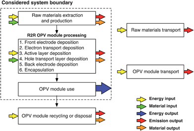 | ||
| Fig. 3 Illustration of the system boundary employed in this LCA (everything inside the dashed line). All stages of the modules produced at Risø DTU are depicted as well as energy/materials inputs/outputs. | ||
Finally, the energy requirements for transport of materials to the manufacturing plant and for transporting the finished solar cell product to the place of use, have been neglected, thus enabling direct comparison with other OPV LCAs that did not include energy requirements for transport. We view it as a safe assumption that it is of low significance per module. Typical values, as given in databases (Ecoinvent 2.143), range from 0.23 MJ kg−1, for road transport to 0.47 MJ kg−1 when it is rail freight. One module weighs much less than 1 kg m−2 and the required chemicals including bottles etc. also weigh less than 1 kg, so the total contribution that transport would account for is maximally on the order of 1 MJ m−2.
Full characterisation of the processes at Risø DTU and all the assumptions are herein detailed. The functional unit for the OPV modules is commonly 1 m2. Note that we use 1 m2 of processed area (290 mm width) from where 45% is the photoactive area. This is a critical issue and has been discussed earlier.40
By compilation of material and energy inventories, the energy input for processing materials and the energy input during module manufacturing can be estimated. This enables a careful determination of the overall embedded energy in the modules, widely called cumulative energy demand (CED). Data related to the OPV processing were acquired in situ from materials consumption and equipment specifications. Energy related to these materials and upstream processes was obtained from databases such as Ecoinvent 2.1,43 through SimaPro (a commercial software widely used for LCA studies) and from the literature. Both thermal and electrical budgets were converted to equivalent primary energy (EPE) at a later stage. The conversion efficiency depends on the technology mix of the electricity supply system and may vary considerably between different countries and also with time. An average of 35% has been considered.6 In the case of thermal energy consumption this was given separately by using the European average factor of 85% to obtain the primary energy equivalent.6
Data used in the assessment, are experimental as already stated; they are not an estimate. Therefore, their quality is considered good. However, a weakness of this approach is that it is based on some assumptions, as there would otherwise be too many uncertainties to allow for a plausible assessment of the product's environmental ‘goodness’. Regarding the OPV research field, on a semi-industrial scale, there is still only information available from one location in the world (Risø DTU). It should thus be recommended that the PV community starts to share information more extensively to balance the view.
Information on the uncertainty of the model outcomes provides useful information for assessing the reliability of LCA-based decisions and for guiding future research towards more accurate life cycle assessments. In order to accommodate this, we have tried to give a qualitative indication of the energy requirements we have estimated, by introducing the following qualifications: ++ very good, + good, 0 fair, − low, −−very low; as will be shown bellow.
LCA generally encompasses an inventory with all cumulative emissions; from the electricity mix and those released to raw materials production/extraction. The emissions inventory presented here is only focused on emissions of CO2 equivalents related to the energy consumption during the manufacture. For the electricity mix of Denmark these emissions amount to 493.80 g-eqCO2 kWel−1 in 2010.44
For its calculation, the required assumptions are a constant OPV module efficiency in the range of 1 to 15%—in agreement with attained performances of up to 3% at Risø DTU for flexible roll-to-roll processed solar cell modules—an insolation level of 1700kWh m−2 per year, typical of southern European countries, and a service lifetime of 15 years. This lifetime can be low as compared to other PV technologies, which easily reach service lifetimes of 20–30 years, but is consistent with the aims of the European Photovoltaic Technology Platform for organic photovoltaics by 2013.45
Through life cycle impact assessment (LCIA) the emissions, consumed resources and other items associated with a system are translated into environmental impacts. There are different methods that can be used to perform a LCIA. Two main approaches are used to classify and characterize environmental impacts: the problem-oriented approach (mid-point) and the damage-oriented approach (end-point). The former can be classified into environmental themes (e.g. greenhouse effect, eutrophication or acidification) whereas the latter also starts by classifying how a system flows into various environmental themes, and model each environmental theme's damage to human health, ecosystem health or damage to resources.
EcoIndicator 99 (end-point)46 is the chosen damage-oriented method that includes the central elements of the LCIA methodology: characterisation, normalisation and weighting, which provide information on the most environmentally damaging materials. For assessing the environmental impacts, SimaPro, with the methods implemented, allowed us to identify the materials which have a detrimental effect in different environmental categories such as Carcinogens, Fossil Fuel depletion, Ecotoxicity and Climate Change.
2 Experimental
2.1 The new polymer solar cell routes
![[thin space (1/6-em)]](https://www.rsc.org/images/entities/char_2009.gif) :
:![[thin space (1/6-em)]](https://www.rsc.org/images/entities/char_2009.gif) PCBM weight ratio was 30
PCBM weight ratio was 30![[thin space (1/6-em)]](https://www.rsc.org/images/entities/char_2009.gif) :
:![[thin space (1/6-em)]](https://www.rsc.org/images/entities/char_2009.gif) 30 mg ml−1. Poly(3,4-ethylenedioxythiophene)
30 mg ml−1. Poly(3,4-ethylenedioxythiophene)![[thin space (1/6-em)]](https://www.rsc.org/images/entities/char_2009.gif) :
:![[thin space (1/6-em)]](https://www.rsc.org/images/entities/char_2009.gif) poly(styrenesulfonate) PEDOT
poly(styrenesulfonate) PEDOT![[thin space (1/6-em)]](https://www.rsc.org/images/entities/char_2009.gif) :
:![[thin space (1/6-em)]](https://www.rsc.org/images/entities/char_2009.gif) PSS was purchased from Agfa (Orgacon EL-P 5010) and diluted with isopropanol in a ratio of 10
PSS was purchased from Agfa (Orgacon EL-P 5010) and diluted with isopropanol in a ratio of 10![[thin space (1/6-em)]](https://www.rsc.org/images/entities/char_2009.gif) :
:![[thin space (1/6-em)]](https://www.rsc.org/images/entities/char_2009.gif) 5 by weight. The ZnO nanoparticle based solution has already been described.47 The aqueous zinc oxide solution was prepared as described earlier48 and was comprised of Zn(OAc)2·2H2O (100 mg mL−1), Al(OH)(OAc)2 (2 mg mL−1) and FS-100 (2 mg ml−1) in water. Three silver inks were used: commercial silver ink, silver ink formulated at Risø, and PV 410 silver ink (Dupont®). The ink for semitransparent silver electrodes was prepared from mixing in a 1
5 by weight. The ZnO nanoparticle based solution has already been described.47 The aqueous zinc oxide solution was prepared as described earlier48 and was comprised of Zn(OAc)2·2H2O (100 mg mL−1), Al(OH)(OAc)2 (2 mg mL−1) and FS-100 (2 mg ml−1) in water. Three silver inks were used: commercial silver ink, silver ink formulated at Risø, and PV 410 silver ink (Dupont®). The ink for semitransparent silver electrodes was prepared from mixing in a 1![[thin space (1/6-em)]](https://www.rsc.org/images/entities/char_2009.gif) :
:![[thin space (1/6-em)]](https://www.rsc.org/images/entities/char_2009.gif) 5 ratio, 18% Ag content ink produced by a method similar to that reported by Hwang et al.49 and butanol. For silver ink nanoparticles (100 ± 15 nm) were dispersed in a 1
5 ratio, 18% Ag content ink produced by a method similar to that reported by Hwang et al.49 and butanol. For silver ink nanoparticles (100 ± 15 nm) were dispersed in a 1![[thin space (1/6-em)]](https://www.rsc.org/images/entities/char_2009.gif) :
:![[thin space (1/6-em)]](https://www.rsc.org/images/entities/char_2009.gif) 1 mixture of triethyleneglycolmonomethylether and ortho-xylene as described earlier.23 The final concentration of silver nanoparticles was 25% (w/v).
1 mixture of triethyleneglycolmonomethylether and ortho-xylene as described earlier.23 The final concentration of silver nanoparticles was 25% (w/v).
![[thin space (1/6-em)]](https://www.rsc.org/images/entities/char_2009.gif) :
:![[thin space (1/6-em)]](https://www.rsc.org/images/entities/char_2009.gif) PCBM/PEDOT
PCBM/PEDOT![[thin space (1/6-em)]](https://www.rsc.org/images/entities/char_2009.gif) :
:![[thin space (1/6-em)]](https://www.rsc.org/images/entities/char_2009.gif) PSS/electrode/barrier. Each module had 16 serially interconnected cells, where the serial connection was achieved upon screen-printing of the metal stripe back-electrode. The narrow silver stripes only served as a serial connection, whereby the thick PEDOT
PSS/electrode/barrier. Each module had 16 serially interconnected cells, where the serial connection was achieved upon screen-printing of the metal stripe back-electrode. The narrow silver stripes only served as a serial connection, whereby the thick PEDOT![[thin space (1/6-em)]](https://www.rsc.org/images/entities/char_2009.gif) :
:![[thin space (1/6-em)]](https://www.rsc.org/images/entities/char_2009.gif) PSS served as current collector.
PSS served as current collector.
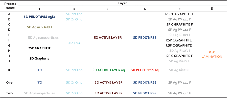 | ||
| Fig. 4 Layers of the manufacturing routes for producing ITO-free solar cells and the reference route ProcessOne. SD stands for Slot die coating, RSP for Rotary screen printing and SP for screen printing. | ||
| Stages of the manufacturing routes | Step | Operation |
|---|---|---|
| Electrode deposition | 1.1 | Slot die coating/Rotary screen Printing |
| 1.2 | Drying | |
| ETL coating | 2.1 | Ink preparation |
| 2.2 | Slot die coating | |
| 2.3 | Drying | |
| Active layer deposition | 3.1 | Ink preparation |
| 3.2 | Slot die coating | |
| 3.3 | Drying | |
| HTL deposition | 4.1 | Ink preparation |
| 4.2 | Slot die coating | |
| 4.3 | Drying | |
| Electrode deposition | 5.1 | Screen printing/Slot die coating/Rotary screen printing |
| 5.2 | Drying | |
| Encapsulation | 6.1 | R2R lamination |
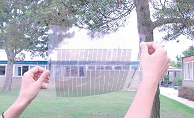 | ||
| Fig. 5 Photograph showing a view through indium-free thin silver based semitransparent front electrode prepared by slot-die coating, using only low temperatures and very little material. This electrode type was explored in this work and presents a sheet resistance < 10 Ω square−1 and an optical transmission of > 50% in the entire visible range of wavelengths. | ||
2.2 Processing and material inventory
Conditions for all the different coating and/or printing processes, and material inventories involved in these steps are detailed in Table 4, Table 5, Table 6 and Table 7. Further details on the equipment were already reported in ref. 30 and 50.| Conditions | |
| Speed | 0.02–2.5 m min−1 |
| Web tension | 80–90N |
| Drying temperature | 140 °C |
| Working corona treater power | 1500 W |
| Working slot die power | 1500 W |
| Working oven power | 12000 W |
| Equipment | |
| Description | R2R printing and coating machine from Grafisk Maskinfabrik A/S comprising unwinder, corona treater, edge guide, Rotary screen printer, flexo unit, coating roller, oven, cooling roller and winding station. |
| Maximum corona treater power | 1500 W |
| Maximum slot die coater power | 1500 W |
| Maximum oven power | 12000 W |
| Material inventory | |
| Front electrode layer | |
| PEDOT:PSS | 39.34 g |
| Silver nanoparticle ink full | 3.68 g |
| Silver ink (18% Ag) | 0.26 g |
| Butanol | 1.29 g |
| Graphene ink | 1.97 ml |
| Active layer | |
| P3HT | 0.08 g |
| PCBM | 0.07 g |
| Chlorobenzene | 6.19 g |
| ELT layer | |
| ZnO (OAc)2 | 3.71 g |
| KOH | 1.86 g |
| MeOH | 12.24 g |
| Acetone | 24.50 g |
| MEA | 0.37 g |
| ZnO(OAc)2 | 0.30 g |
| Water | 2.95 g |
| HTL layer | |
| PEDOT:PSS | 26.23 g |
| Isopropanol | 38.89 g |
| Back electrode layer | |
| Silver for interconnections | 0.63 g |
| Conditions | |
| Speed | 1 m min−1 |
| Residence time in oven | 72 s |
| Drying temperature | 140 °C |
| Working screen printer power | 1500 W |
| Equipment | |
| Description | Alraun printer comprising unwinder, metering wheel, positioning camera, vacuum table, screen printer (AT701), hot air oven, transport rollers, dancing tensioning roller and rewinder. |
| Maximum screen printer power | 38000 W |
| Material inventory | |
| Back electrode layer | |
| Silver ink PV410 full | 19.67 g |
| Graphite full | 19.67 g |
| Conditions | |
| Speed | 3 m min−1 |
| Drying temperature | 140 °C |
| Working RS printer power | 200 W |
| Working oven power | 12000 W |
| Equipment | |
| Description | R2R printing and coating machine from Grafisk Maskinfabrik A/S comprising unwinder, corona treater, edge guide, Rotary screen printer, flexo unit, coating roller, oven, cooling roller and winding station. |
| Maximum RS printer power | 1500 W |
| Maximum oven power | 21000 W |
| Material inventory | |
| Front and back electrode layer | |
| Graphite full | 4.59 g |
| Graphite interconnections | 0.79 g |
| Conditions | |
| Speed | 120 m h−1 |
| Working laminator power | 1500 W |
| Equipment | |
| Description | Laminator comprising unwinder, edge guide and cutting table, laminator, laminate unwinder, longitudinal cutting knifes and rewinder. |
| Maximum power | 1500 W |
| Material inventory | |
| Adhesive (3M 467 MPF) | 20.24 g |
| PET encapsulation | 61.65 g |
3 Results
Energy embedded in materials
Using the material inventory compiled in Table 4, Table 5, Table 6 and Table 7, the energy needed for manufacturing the materials was computed for Processes A to K, and for Process Two.When the CED for a specific material was not available in the Ecoinvent database, it was necessary to calculate the energy content of a raw material or ink from scratch; i.e. from its basic components. Silver for the transparent electrodes is a non-particle conductive ink containing in its formula 18% silver. It has been estimated to require energy for its production of as much as 275 MJ kg−1 and as low as 126 MJ kg−1, thus resulting in 200.5 MJ kg−1 on average. This is very close to estimations done for PV 410 silver ink (from Dupont®) in previous studies.11 The silver ink was then diluted in butanol 1![[thin space (1/6-em)]](https://www.rsc.org/images/entities/char_2009.gif) :
:![[thin space (1/6-em)]](https://www.rsc.org/images/entities/char_2009.gif) 5 (v/v); the energy embedded in butanol is 81.02 MJ kg−1 according to the Ecoinvent database. Printable graphite conductive ink was estimated to embed 174.82 MJ kg−1. Since the solid content in its formula can vary from 34 to 37%, an average of 36.5% was estimated (as shown in Table 8). With the aim to prove whether the solid content of the ink can affect the results, a sensitivity study was conducted, by varying this parameter from 0 to 100%, and no significant influence was found. Even if the embodied energy would increase by 200%, the variation of EPBT would remain below 3% of its initial value.
5 (v/v); the energy embedded in butanol is 81.02 MJ kg−1 according to the Ecoinvent database. Printable graphite conductive ink was estimated to embed 174.82 MJ kg−1. Since the solid content in its formula can vary from 34 to 37%, an average of 36.5% was estimated (as shown in Table 8). With the aim to prove whether the solid content of the ink can affect the results, a sensitivity study was conducted, by varying this parameter from 0 to 100%, and no significant influence was found. Even if the embodied energy would increase by 200%, the variation of EPBT would remain below 3% of its initial value.
| Embedded energy (MJEPE) | Units | Embedded energy (MJEPE) | Certainty in energy data | |
|---|---|---|---|---|
| Per kg m−2 | Per FU | Per FU | ||
| PET substrate | 80.75 | 0.0616500 | 4.98 | ++ |
| Electrode ink (graphite) | 174.82 | 0.0045902 | 0.80 | 0 |
| Zn(OAc)2 | 42.07 | 0.0002951 | 0.01 | ++ |
| P3HT | 1809.52 | 0.0000836 | 0.15 | + |
| PCBM | 11061.31 | 0.0000669 | 0.74 | + |
| Chlorobenzene | 61.58 | 0.0061869 | 0.38 | ++ |
| Isopropanol | 62.74 | 0.0388852 | 2.44 | ++ |
| PEDOT:PSS | 159.41 | 0.0262295 | 4.18 | + |
| Back electrode (silver) | 309.22 | 0.0006330 | 0.20 | + |
| Adhesive | 200.00 | 0.0202400 | 4.05 | + |
| PET encapsulation | 80.75 | 0.0616500 | 4.98 | ++ |
| SUBTOTAL | 22.91 |
The graphene ink was prepared according to a method described by Hummers and Offerman51 from natural graphite, and found to range from 200 to 400 MJ kg−1. With regard to the ETL, zinc oxide ink, and HTL, PEDOT:PSS, had already been studied in the LCA studies for ProcessOne,11 as well as Photoactive inks, solvents and other chemicals (potassium hydroxide, acetone, chlorobenzene, etc.).
The contribution to the embodied energy for each process is shown in Fig. 6. The electrode ink appears to have a greater contribution for processes A and B, which is due to the fact that PEDOT:PSS has a large embodied energy (159.41 MJEPE kg−1) and is used in large amounts in those two processes.
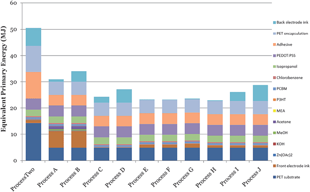 | ||
| Fig. 6 Embodied energy in the materials per functional unit (m2) in processes from A to J (MJEPE), ITO processes (ProcessOne and Process K) are not shown since they are significantly out of scale. | ||
3.2 Direct process energy
The R2R techniques that have been used for the production of solar cells are: slot-die coating, screen printing and rotary screen printing. Thus, the energy requirements at the R2R line are purely electrical. By computing the manufacturing time per functional unit (1 m2) we can calculate the electrical consumption for all the equipment involved as shown in Table 9.| A | B | C, D | E | F | G, H | I, J | |
|---|---|---|---|---|---|---|---|
| S1 Front electrode processing | |||||||
| Electrode coating | 204.92 | 204.92 | 32.79 | 65.57 | 32.79 | 10.93 | 163.93 |
| Drying | 1844.26 | 1844.26 | 262.30 | 262.30 | 262.30 | 245.90 | 737.70 |
| S2 ET layer deposition | |||||||
| ZnO ink preparation | 27.83 | 27.83 | 0 | 0 | 0 | 0 | 0 |
| ZnO coating SD | 81.97 | 81.97 | 81.97 | 81.97 | 81.97 | 81.97 | 81.97 |
| Drying | 368.85 | 368.85 | 368.85 | 368.85 | 368.85 | 368.85 | 368.85 |
| S3 Active layer deposition | |||||||
| P3HT:PCBM ink preparation | 5.57 | 5.57 | 5.57 | 5.57 | 5.57 | 5.57 | 5.57 |
| P3HT:PCBM coating SD | 40.98 | 40.98 | 40.98 | 40.98 | 40.98 | 40.98 | 40.98 |
| Drying | 368.85 | 368.85 | 368.85 | 368.85 | 368.85 | 368.85 | 368.85 |
| S4 PEDOT :PSS deposition | |||||||
| PEDOT:PSS ink preparation | 1.31 | 1.31 | 1.31 | 1.31 | 1.31 | 1.31 | 1.31 |
| PEDOT:PSS slot die coating | 74.52 | 74.52 | 74.52 | 74.52 | 74.52 | 74.52 | 74.52 |
| Drying | 670.64 | 670.64 | 670.64 | 670.64 | 670.64 | 670.64 | 670.64 |
| S5 Back electrode deposition | |||||||
| Slot die coating | 10.93 | 5.46 | 5.46 | 65.57 | 10.93 | 10.93 | 5.46 |
| Drying | 245.90 | 409.84 | 409.84 | 295.08 | 245.90 | 245.90 | 409.84 |
| S6 Lamination | |||||||
| Encapsulation by R2R lamination | 4.10 | 4.10 | 4.10 | 4.10 | 4.10 | 4.10 | 4.10 |
| SUBTOTAL (W el ) | 3950.63 | 4109.10 | 2332.64 | 2305.32 | 2168.71 | 2130.46 | 2933.74 |
| SUBTOTAL (MJ EPE ) | 40.64 | 42.27 | 23.94 | 23.71 | 22.31 | 21.91 | 30.18 |
When comparing the share of the direct process energy in the manufacturing steps for processes from A to K, with ProcessOne and ProcessTwo (Fig. 7), we find that an enormous decrease is attainable, although the use of PEDOT:PSS as HTL is still appearing as the most energy demanding step. This is also observed when PEDOT:PSS acts as front electrode (e.g. the green coloured part of the bar chart for Processes A and B in Fig. 7) because of the low web speed employed and the consequently higher thermal input for drying.
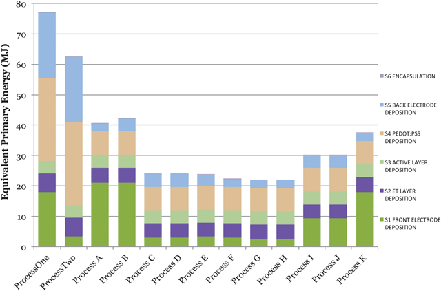 | ||
| Fig. 7 Direct process energy employed for different steps in the manufacturing of OPV modules by routes A to K, and by ProcessOne and ProcessTwo. | ||
The process with a semi-transparent silver-based electrode, named Process H, has the lowest embedded energy. The energy balance for Process H has been shown in Fig. 8.
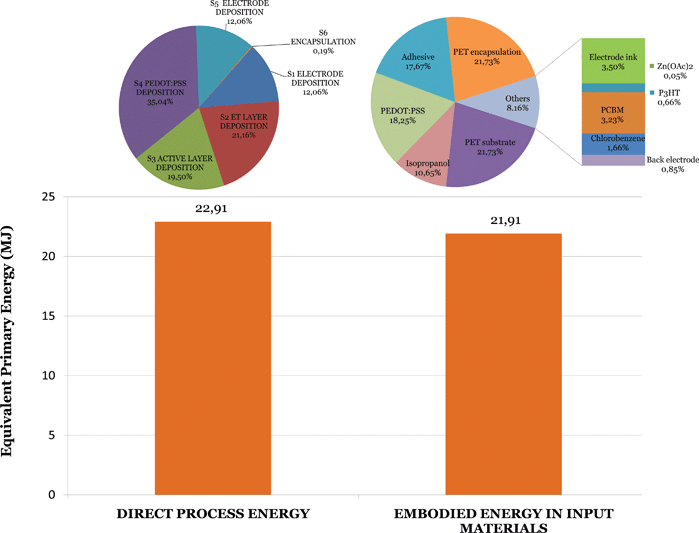 | ||
| Fig. 8 Materials inventory share and direct process energy in Process H, both given in equivalent primary energy (MJEPE). | ||
3.3 Environmental impacts
The environmental impact of PET used as substrate and barrier encapsulation in these routes, shown in Fig. 9, is particularly high since it is being produced by polymerization of two petroleum-based raw materials. This causes depletion of fossil fuel resources. Electricity consumed by the manufacturing equipment during manufacture also has a strong effect on fossil fuels since electrical input is produced to a large extent from fossil fuels in Denmark (80% of them in the electricity mix, 20% of the mix comes entirely from renewable sources).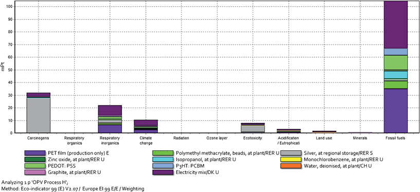 | ||
| Fig. 9 Impact categories assessment weighted according to the raw materials used in the production of polymer solar cells by Process H. The methodology employed has been Eco-indicator 99, implemented in the SimaPro software, and developed under the Dutch NOH Programme by PRé Consultants. | ||
Nonetheless, when comparing damaging impacts of ProcessOne, ProcessTwo and Process H (Fig. 10), there is a trend in the way of generally diminishing impacts, even in the high impacted fossil fuels category. One can thus conclude that the methodology has allowed for the successful development of a process that is more efficient at all levels.
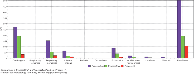 | ||
| Fig. 10 Impact categories assessment corresponding to ProcessOne, ProcessTwo and Process H, weighted according Eco-indicator 99, implemented in the SimaPro software, and developed under the Dutch NOH Programme by PRé Consultants. | ||
4 Traversing the learning curve towards shorter EPBT
The processes developed have a significantly shorter energy payback time than the reference process, named ProcessOne. Among the batch of new routes, Process H, an EPBT of 1.42–0.71 years is achievable with a power conversion efficiency of respectively 0.5–1%. In comparison to ProcessOne with an energy payback time of 2.02–1.35 years for respectively 2–3% efficiency this is a great leap forward and shows that it is possible to achieve a shorter energy payback time for a solar cell that at least in terms of efficiency is a poorer performer. It is also a less refined version and it can certainly be justified to assume that this can be improved even further, pending the same investment in development that i.e. ProcessOne has received. In Fig. 11 some of those avenues for improvement have been highlighted and they have been divided into two groups according to their feasibility. One group represents how much improvement one could obtain by making very realistic developments and a second group shows how much improvement could be achieved provided that some more challenging yet realistic developments were made. Those latter assumptions will require some innovation (the former do not).4.1 The Feasible improvements
When examining Fig. 8 and Fig. 11 it is clear that the equivalent primary energy has been balanced both in terms of energy embedded in the materials and in the direct process energy. This has led to a reduction of the equivalent primary energy by a factor of ∼10. Further improvements should obviously address the individual slices in the pie charts without leading to large unbalance. In terms of the direct process energy it is possible to introduce renewable energy sources very easily due to the fact that the running of a polymer solar cell printing and coating machine requires very little electricity and relatively little thermal energy. The low temperatures involved imply that a polymer solar cell production plant can be easily operated using solar electricity and solar thermal energy for drying and curing (the drying steps account for almost 90% of the total direct energy). It should be emphasized that the enabling feature is the low temperatures involved for OPV and this approach is unlikely to be efficiently applicable to PV technologies that require heating steps with temperatures much above 150 °C. Since PET is the largest contributor to the embodied energy in the module, a reduction in the thickness of the barrier—but also the adhesive—would decrease the embedded energy significantly. It should be possible to make an entirely functional encapsulated device with a thickness of 50–70 micron. Future work should also address the assessment of environmental impacts of a different range of potential plastic materials used as substrate in OPV modules: less-damaging, biodegradable or, even, recyclable plastics. Recycling organic photovoltaic scrap and re-introducing the waste as raw material in the manufacture is a cost-cutting measure but could also make the technology more sustainable: a real cradle-to-cradle technology.Further improvements are obvious and the only reason they were not implemented in this work is due to the fact that a laboratory/pilot line was employed. Here a processing width of 305 mm with a working width of 250 mm is a constraint but a trivial one. Experiments with larger working widths have been shown to be very feasible.
Processing methods that enable full use of the processed area would be desirable. In the current version of Process H only 45% of the solar cell area is active and it has been shown that one can easily improve this to 67% and quite readily improve it to 85% and this significantly impacts the EPBT. Minor improvements would come from replacing the organic solvents employed with water as this has also been demonstrated as being possible.48,52
4.2 The Challenging improvements
There are several achievable improvements that would require some innovation and therefore they represent valuable research targets. As shown in Fig. 11 and Table 10, these will only lead to a smaller improvement as compared to the feasible improvements described above. Of those the simultaneous formation of several layers in the solar cell stack would (provided that the technical yield is not compromised) lead to both reductions in energy usage and an improvement in overall processing speed. We also applied the projections for efficiency and lifetime set forward by the EC. Finally, recycling or end of use handling was also considered. The beneficial effects of recycling are difficult to estimate and we considered the energy gained by combustion of the solar cell and recovery of the metals (Ag and Zn) from the ashes.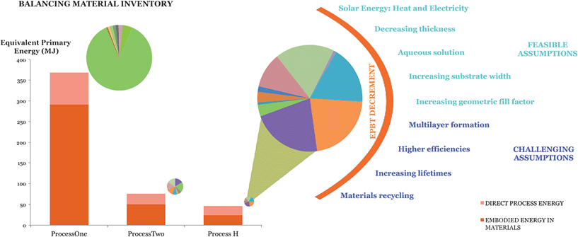 | ||
| Fig. 11 Balancing the inventory of the polymer solar cells is crucial for making improvements even if this implies a sacrifice in performance. ProcessOne clearly has an unbalanced inventory with one component (the ITO-electrode) representing the majority of the equivalent primary energy (see pie-chart). By developing the polymer solar cell with the sole aim to balance the inventory and minimize the equivalent primary energy yields significantly lower values and a very balanced inventory. | ||
| Efficiency | 0.25% | 0.5% | 0.7% | 1% | 2% | 3% | 5% | 10% | 15% |
|---|---|---|---|---|---|---|---|---|---|
| ProcessOne | 5938.7 | 2969.4 | 2120.9 | 1484.7 | 742.0 | 494.8 | 296.9 | 148.5 | 98.9 |
| Process H | 1034 | 517 | 369 | 259 | 129 | 86 | 52 | 26 | 17 |
| Feasible assumptions | 210 | 105 | 75 | 52 | 26 | 17 | 10 | 5 | 3 |
| Challenging assumptions | 82 | 41 | 29 | 21 | 10 | 7 | 4 | 2 | 1 |
The developments made from ProcessOne through Process H enable one to traverse the EPBT-efficiency plot i.e. to achieve significantly lower EPBT with lower efficiency (Fig. 12) and further improvements can be made through easily applicable and more challenging improvements. It is noticeable that the LCA directed improvements lead to improvements yielding better EPBT, despite the trade-off in performance; i.e. jumping from ProcessOne to Process H and further again—by assuming straightforward and more demanding challenges—means going down and left in the plot.
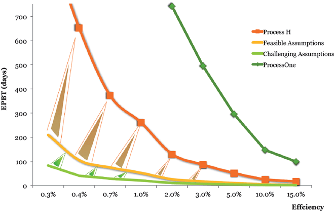 | ||
| Fig. 12 Evolution of the EPBT guided by analysis (note that the scale is not linear). | ||
4.3 The factory
It was clear from Table 1 that the most performing renewable energy source is wind energy with energy payback times on the order of 95–140 days. It should be highlighted that this impressively fast energy payback time has been arrived at through a maturation of the technology over many years of operation and also that the technology does not scale with the 1-gigawatt-a-day challenge. This has been addressed within the wind energy sector by attempting to make larger and larger wind turbines placed in the most windy regions of the world (typically off shore). World energy demand is expected to increase by 50% each decade13 and is estimated to reach 15 TW by 2050 as mentioned above. Global demand for each energy source will therefore increase, with fossil fuels accounting for over one-half of the increase in total primary energy demand. In one scenario where the electricity demand would be provided by PV, or in particular OPV, the manufacture of a 1 GW energy production capacity every day for satisfying this demand would be required. We envisage that the 1-gigawatt-a-day challenge can be efficiently addressed by OPV by assuming an operational lifetime of 1 year and a power conversion efficiency of 10%. This would require 1000 factories distributed around the globe near the equator in regions with high levels of insolation and in areas where land mass is accessible (i.e. desserts). This could also be viewed as a political instrument to lift developing regions of the world by providing them with an industry for covering the world needs. To illustrate this solution we consider a simple manufacturing installation (Fig. 13) that is 1/100 scale of the full size factory (i.e. 1/100.000 scale that fully addresses the 1-gigawatt-a-day challenge). We envisage the factory to be situated in southern Spain where the insolation reaches more than 1700 kWh m−2 per year.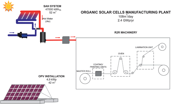 | ||
Fig. 13 A factory for manufacturing polymer solar cells using solar electric and solar thermal energy. The annual production capacity is 100![[thin space (1/6-em)]](https://www.rsc.org/images/entities/char_2009.gif) 000th of what would be required to fully address the 1-gigawatt-a-day challenge. 000th of what would be required to fully address the 1-gigawatt-a-day challenge. | ||
It is evident that the factory is quite small both in terms of the solar electric and solar thermal installations, making the full-scale factory very realistic. The daily production capacity of only 108 m2 also imply that the larger factory is easily envisaged. It is in fact possible to consider that significantly less and larger factories can address the problem since foil handling by printing and coating is currently achieved on the scale of 100![[thin space (1/6-em)]](https://www.rsc.org/images/entities/char_2009.gif) 000–1
000–1![[thin space (1/6-em)]](https://www.rsc.org/images/entities/char_2009.gif) 000
000![[thin space (1/6-em)]](https://www.rsc.org/images/entities/char_2009.gif) 000 square metres a day. The choice of 1000 factories on a full scale was conceived to balance the system such that a very distributed manufacture across the globe is achieved. This ensures stability in terms of manufacture, electricity production and sensitivity (to insolation and politics). There are naturally challenges associated with the land use but it is noticeable that the manufacture of polymer solar cells according to Process H on a scale that fully addresses the 1-gigawatt-a-day challenge does not put any significant restraints on the current materials use. We have summarized in Table 11 the annual production of the various raw materials that enter the process and it is clear that even on a full scale (manufacture of 107 m2 per day) this effort would claim very little of the currently employed materials. It is thus unlikely that an effort as outlined here would significantly affect the global raw materials cost due to speculation in raw materials as relatively little is required (significantly less than 3% of the world production for any of them).
000 square metres a day. The choice of 1000 factories on a full scale was conceived to balance the system such that a very distributed manufacture across the globe is achieved. This ensures stability in terms of manufacture, electricity production and sensitivity (to insolation and politics). There are naturally challenges associated with the land use but it is noticeable that the manufacture of polymer solar cells according to Process H on a scale that fully addresses the 1-gigawatt-a-day challenge does not put any significant restraints on the current materials use. We have summarized in Table 11 the annual production of the various raw materials that enter the process and it is clear that even on a full scale (manufacture of 107 m2 per day) this effort would claim very little of the currently employed materials. It is thus unlikely that an effort as outlined here would significantly affect the global raw materials cost due to speculation in raw materials as relatively little is required (significantly less than 3% of the world production for any of them).
| Materials | Units per FU (g m−2) | Consumption (tonne/yr) | Yearly production (tonne/yr) | Share (%) |
|---|---|---|---|---|
| PET substrate | 123.30 | 277425.00 | 4.90E + 07 | 0.57 |
| Silver | 0.63 | 42.52 | 19051.00 | 0.22 |
| Adhesive | 20.24 | 45540.00 | 2.05E + 06 | 2.22 |
| Zn | 0.30 | 663.93 | 1.00E + 07 | 0.007 |
| Water | 2.95 | 6639.34 | — | — |
| P3HT | 0.08 | 188.11 | — | — |
| PCBM | 0.07 | 150.49 | — | — |
| Chlorobenzene | 6.19 | 13905.00 | — | — |
| Isopropanol | 38.89 | 87491.80 | — | — |
| PEDOT:PSS | 26.23 | 59016.39 | — | — |
| Graphite | 4.59 | 10327.50 | — | — |
5 Future and outlook
It should be evident that polymer solar cells house the potential to address the world’s increasing energy needs. It is clear that there are several new developments in terms of system’s integration that also need to be addressed. We estimate that the distribution of manufacturing facilities throughout the world will limit the extra cost associated with transport. We also find it highly likely that obvious questions of how one would distribute solar cells on this scale, connect them and replace them every year (or every few years as lifetime improves) can be solved. The most rational solution would include a structure that, depending on the location, would endure for many years thus requiring only replacement of the solar cell modules. It could be a concrete, steel or wooden structure. It is also of some importance to develop new connection methodologies and inverters that match this application. Operation at high voltages is likely to minimize resistive losses and will lead to lower use of conductor materials. The potential availability of surfaces on roofs and/or façades in existing and new buildings for building of integrated PV systems is also large in the developed regions of the world. We however consider the distribution in the form of solar farms in currently less developed regions as presenting a larger potential both in terms of development of poor regions and in terms of efficiency of scale.6 Conclusions
We have demonstrated how the polymer solar cell technology can traverse the learning curve in terms of energy payback time and present shorter energy payback times through development according to directions arrived at through life cycle assessments, even when the efficiency is poorer. This is a clearly distinguishing feature of the polymer solar cell and confirms it as being a disruptive technology. We found that the use of renewable energy is particularly well suited to polymer solar cell manufacture, which is in stark contrast to all other PV technologies including other 3rd generation photovoltaics. We describe the requirements for a factory based on those observations and find that the manufacture of OPV at a rate equivalent to an electricity production capacity of 1 GWp day−1 is possible while claiming very little of the available resources (significantly less than 3% at all levels). We finally observe that energy payback times as short as one day are possible when accounting for the projected performance in terms of stability and efficiency.Acknowledgements
This work has been supported by the Danish Strategic Research Council (2104-07-0022) and EUDP (j.no. 64009-0050); also by the Spanish Ministry of Science and Innovation (Consolider-HOPE CSD2007-00007), and by Comunidad Autónoma de la Región de Murcia (CARM-D429-2008). Partial financial support was also received from the European Commission as part of the Framework 7 ICT 2009 collaborative project HIFLEX (grant no. 248678) from the EUIndian framework of the “Largecells” project that received funding from the European Commission's Seventh Framework Programme (FP7/2007–2013. grant no. 261936) and from PVERA-NET (project acronym POLYSTAR).References
- World Energy Outlook, International Energy Agency, 2010 Search PubMed.
- B. Sills, http://www.bloomberg.com/news/2011-08-29/solar-may-produce-most-of-world-s-power-by-2060-iea-says.html.
- L. Schleisner, Renewable Energy, 2000, 20, 279–288 CrossRef CAS.
- E. A. Alsema and M. J. de Wild-Scholten, 20th European Photovoltaic Solar Energy Conference and Exhibition, Barcelona, Spain, 2005 Search PubMed.
- K. Knapp and T. Jester, Sol. Energy, 2001, 71, 165–172 CrossRef CAS.
- E. A. Alsema, Renewable Sustainable Energy Rev., 1998, 2, 387–415 CrossRef CAS.
- M. Raugei, S. Bargigli and S. Ulgiati, Energy, 2007, 32, 1310–1318 CrossRef CAS.
- K. Kato, T. Hibino, K. Komoto, S. Ihara, S. Yamamoto and H. Fujihara, Sol. Energy Mater. Sol. Cells, 2001, 67, 279–287 CrossRef CAS.
- A. L. Roes, E. A. Alsema, K. Blok and M. K. Patel, Progr. Photovolt.: Res. Appl., 2009, 17, 372–393 CrossRef CAS.
- R. García-Valverde, J. A. Cherni and A. Urbina, Prog. Photovoltaics, 2010, 18, 535–558 Search PubMed.
- N. Espinosa, R. García-Valverde, A. Urbina and F. C. Krebs, Sol. Energy Mater. Sol. Cells, 2011, 95, 1293–1302 CrossRef CAS.
- L. Gagnon, C. Bélanger and Y. Uchiyama, Energy Policy, 2002, 30, 1267–1278 CrossRef.
- M. Pehnt, Renewable Energy, 2006, 31, 55–71 CrossRef.
- D. Y. C. Leung, X. L. Yin and C. Z. Wu, Renewable Sustainable Energy Rev., 2004, 8, 565–580 CrossRef CAS.
- W. G. Hohenstein and L. L. Wright, Biomass Bioenergy, 1994, 6, 161–173 CrossRef.
- M. W. Rowell, M. A. Topinka, M. D. McGehee, H.-J. Prall, G. Dennler, N. S. Sariciftci, L. Hu and G. Gruner, Appl. Phys. Lett., 2006, 88, 233506–233506 CrossRef.
- J. van de Lagemaat, T. M. Barnes, G. Rumbles, S. E. Shaheen, T. J. Coutts, C. Weeks, I. Levitsky, J. Peltola and P. Glatkowski, Appl. Phys. Lett., 2006, 88, 233503 CrossRef.
- V. C. Tung, L.-M. Chen, M. J. Allen, J. K. Wassei, K. Nelson, R. B. Kaner and Y. Yang, Nano Lett., 2009, 9, 1949–1955 CrossRef CAS.
- Y. Wang, X. Chen, Y. Zhong, F. Zhu and K. P. Loh, Appl. Phys. Lett., 2009, 95, 063302 CrossRef.
- J. Wu, M. Agrawal, H. A. Becerril, Z. Bao, Z. Liu, Y. Chen and P. Peumans, ACS Nano, 2010, 4, 43–48 CrossRef CAS.
- S. Bae, H. Kim, Y. Lee, X. Xu, J.-S. Park, Y. Zheng, J. Balakrishnan, T. Lei, H. Ri Kim, Y. I. Song, Y.-J. Kim, K. S. Kim, B. Ozyilmaz, J.-H. Ahn, B. H. Hong and S. Iijima, Nat. Nanotechnol., 2010, 5, 574–578 CrossRef CAS.
- A. R. Madaria, A. Kumar and C. Zhou, Nanotechnology, 2011, 22, 245201 CrossRef.
- F. C. Krebs, Org. Electron., 2009, 10, 761–768 CrossRef CAS.
- S.-I. Na, S.-S. Kim, J. Jo and D.-Y. Kim, Adv. Mater., 2008, 20, 4061–4067 CrossRef CAS.
- F. C. Krebs, Sol. Energy Mater. Sol. Cells, 2009, 93, 1636–1641 CrossRef CAS.
- Y. Galagan, J.-E. J. M. Rubingh, R. Andriessen, C.-C. Fan, P. W. M. Blom, S. C. Veenstra and J. M. Kroon, Sol. Energy Mater. Sol. Cells, 2011, 95, 1339–1343 CrossRef CAS.
- M. Manceau, D. Angmo, M. Jørgensen and F. C. Krebs, Org. Electron., 2011, 12, 566–574 CrossRef CAS.
- B. Zimmermann, H.-F. Schleiermacher, M. Niggemann and U. Würfel, Sol. Energy Mater. Sol. Cells, 2011, 95, 1587–1589 CrossRef CAS.
- Materials, Applications and Opportunities in Organic Photovoltaics, Nanomarkets, 2011 Search PubMed.
- F. C. Krebs, J. Fyenbo and M. Jørgensen, J. Mater. Chem., 2010, 20, 8994–9001 RSC.
- F. C. Krebs, T. D. Nielsen, J. Fyenbo, M. Wadstrøm and M. S. Pedersen, Energy Environ. Sci., 2010, 3, 512–525 CAS.
- F. C. Krebs, J. Fyenbo, D. M. Tanenbaum, S. A. Gevorgyan, R. Andriessen, B. van Remoortere, Y. Galagan and M. Jørgensen, Energy Environ. Sci., 2011, 4, 4116–4123 CAS.
- (a) J. Kalowekamo and E. Baker, Sol. Energy, 2009, 83, 1224–1231 CrossRef CAS; (b) S. B. Darling, F. You, T. Veselka and A. Velosa, Energy Environ. Sci., 2011, 4, 3133–3139 RSC.
- C. Powell, T. Bender and Y. Lawryshyn, Sol. Energy, 2009, 83, 1977–1984 CrossRef CAS.
- B. Azzopardi, C. J. M. Emmott, A. Urbina, F. C. Krebs, J. Mutale and J. Nelson, Energy Environ. Sci., 2011, 4, 3741–3753 Search PubMed.
- E. A. Alsema and M. J. de Wild-Scholten, in Materials Research Society Fall 2005 Meeting, Boston, 2005 Search PubMed.
- N. Jungbluth, Progr. Photovolt.: Res. Appl., 2005, 13, 429–446 CrossRef.
- E. A. Alsema and E. Nieuwlaar, Energy Policy, 2000, 28, 999–1010 CrossRef.
- F. C. Krebs, S. A. Gevorgyan and J. Alstrup, J. Mater. Chem., 2009, 19, 5442–5451 RSC.
- N. Espinosa, R. García-Valverde, F. Lenzmann, A. Urbina and F. C. Krebs, Sol. Energy Mater. Sol. Cells, 2011 DOI:10.1016/j.solmat.2011.09.048.
- ISO 14044: Environmental management – Life cycle assessment – Requirements and guidelines, International Organisation for Standardisation (ISO), Geneve, 2006 Search PubMed.
- Handbook for Life cycle assessment using the GaBi Education Software Package, PE International, 2009 Search PubMed.
- Ecoinvent Centre, 2011.
- Danish Energy Agency, 2011.
- A Strategic Research Agenda for Photovoltaic Solar Energy Technology, European Photovoltaic Technology Platform, 2007 Search PubMed.
- M. Goedkoop and R. Spriemsma, The Eco-indicator 99 – A damage-oriented method for Life Cycle Impact Assessment, PRé Consultants, 1999 Search PubMed.
- F. C. Krebs, Y. Thomann, R. Thomann and J. W. Andreasen, Nanotechnology, 2008, 19, 424013 CrossRef.
- R. Søndergaard, M. Helgesen, M. Jørgensen and F. C. Krebs, Adv. Energy Mater., 2011, 1, 68–71 CrossRef.
- E. Hwang, S. Lee, Y. Lyu, J. Yim, J. Kim, S. Chang, L. Pu and Byun, Mater. Sci. Eng., B, 2005, 117, 11–16 CrossRef.
- F. C. Krebs, T. Tromholt and M. Jørgensen, Nanoscale, 2010, 2, 873–886 RSC.
- W. S. Hummers and R. E. Offeman, J. Am. Chem. Soc., 1958, 80, 1339 CrossRef CAS.
- T. R. Andersen, T. T. Larsen-Olsen, B. Andreasen, A. P. L. Böttiger, J. E. Carlé, M. Helgesen, E. Bundgaard, K. Norrman, J. W. Andreasen, M. Jørgensen and F. C. Krebs, ACS Nano, 2011, 5, 4188 CrossRef CAS.
| This journal is © The Royal Society of Chemistry 2012 |
