Enhanced electro-optic coefficient (r33) in nonlinear optical chromospheres with novel donor structure†
Jieyun
Wu
ab,
Jialei
Liu
a,
Tingting
Zhou
ab,
Shuhui
Bo
*a,
Ling
Qiu
a,
Zhen
Zhen
a and
Xinhou
Liu
a
aKey Laboratory of Photochemical Conversion and Optoelectronic Materials, Technique Institute of Physics and Chemistry, Chinese Academy of Sciences, Beijing, 100190, China. E-mail: boshuhui@mail.ipc.ac.cn
bGraduated University of Chinese Academy of Sciences, Beijing, 100049, China
First published on 16th December 2011
Abstract
The synthesis and characterization of new push-pull chromophores A and B, from tricyanofuran (TCF) electron withdrawing and various electron donating moieties, have been demonstrated to compare the roles of donors in electro-optic performance. The crystal structure analyses of the intramolecular hydrogen bond, molecular coplanarity and π–π interactions reveal that A forms cross-stacking, while B forms antiparallel dimer packing, which indicates weaker intermolecular interactions of A than B. Also, the photophysical properties, solvatochromic behavior and Density Functional Theory (DFT) calculations were also investigated. In electro-optic activities, the doped films-A containing chromophore A display an r33 value of 36 pm V−1 at the saturated doping concentration of 40 wt%, while the doped films-B containing B show a maximum r33 value of 16 pm V−1 at the saturated concentration of 25 wt%. High loading density and high r33 value indicate that the chromophore A with julolidinyl-based donor can efficiently reduce the interchromophore electrostatic interactions and enhance the macroscopic optical nonlinearity, showing that chromophore A with julolidinyl-based donor has promising applications in nonlinear optical (NLO) materials.
Introduction
The development of the highly efficient organic electro-optic (EO) materials has been the focus of recent research for many organic materials research groups because of their attractive potential in such applications as optical date transmission and optical information processing. The organic and polymeric nonlinear optical (NLO) materials have many advantages over inorganic materials, such as large nonlinear optical coefficients, ease of synthetic design, simple preparation and low cost.1–5 One of the major challenges in the research of organic NLO materials is the rational design of NLO chromophores to optimize their molecular hyperpolarizability (β) and to translate these β values into bulk EO activities together with improvement of thermal and photochemical stability.2,6–10Most chromophores have a π–electron conjugated structure coupled to electron donor and electron acceptor units. In particular, high βchromophores, which conjugate 2-dicyanomethylene-3-cyano-4,5,5-dimethyl-2,5-dihydrofuran (TCF) and 2-dicyanomethylene-3-cyano-4,5-dimethyl-5-trifluoromethyl-2,5-dihydrofuran(CF3-TCF), display excellent EO coefficient.1,11,12 Although more and more NLO chromophores with high hyperpolarizability have been synthesized, translating large microscopic hyperpolarizability into large macroscopic EO response (r33) is still a challenge to the NLO research, which may significantly depend on the intermolecular actions, for instance, π–π stacking and charge transport between chromophores.4,13,14 Moreover, weak non-covalent interactions such as CH⋯X (X![[double bond, length as m-dash]](https://www.rsc.org/images/entities/char_e001.gif) O, N, S, halogen), π–π stacking and XH⋯π (X = O, N, C) play important roles in chromophore arrangement and poling process.15,16 Obviously, the X-ray single-crystal structural analysis is an important approach in determining the molecular structure and providing essential information to investigate the intermolecular actions and chromophore packing. Due to the sophisticated structure and difficulty of the crystal growth of chromophores, very few research examples have been carried out into the chromophore interactions through investigating the crystal structure.15–21
O, N, S, halogen), π–π stacking and XH⋯π (X = O, N, C) play important roles in chromophore arrangement and poling process.15,16 Obviously, the X-ray single-crystal structural analysis is an important approach in determining the molecular structure and providing essential information to investigate the intermolecular actions and chromophore packing. Due to the sophisticated structure and difficulty of the crystal growth of chromophores, very few research examples have been carried out into the chromophore interactions through investigating the crystal structure.15–21
Many studies have been conducted on the investigation of electron acceptors and π–electron bridges in the synthesis of chromophores, but few have investigated the effect of donor units on macroscopic EO coefficient.22–29 This paper describes our experimental approach to the design and synthesis of two new NLO chromophoresA and B (Scheme 1) containing the same vinylene bridge and TCF acceptor, yet different donors. ChromophoreA has the 8-benzyloxy-1,1,7,7-tetramethyl-julolidinyl group as the donor. ChromophoreB, which has 2-benzyloxy-4-(diethyl amino)benzyl group as the donor, and has been synthesized as a benchmark chromophore for comparison. ChromophoreA with a 12-membered ring donor has large three-dimensional steric hindrances. Thermal stability, photophysical properties, DFT calculation results and nonlinear optical properties of the chromophores were systematically compared to prove the benefits of the julolidinyl-based donor in applications of nonlinear optical chromophores design and synthesis. In this article, we outlined the results of our systematic single-crystal X-ray diffraction structural analysis of the two new chromophores. The comparison of their crystal structures and supramolecular interactions has been comprehensively shown by crystal information and theoretical calculation.
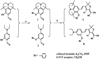 | ||
| Scheme 1 Chemical structures and synthetic scheme for chromophoresA and B. | ||
Results and discussion
Scheme 1 shows the chemical structures of chromophoresA and B and their synthetic approaches. The donor parts 1 and 2 were obtained by a Williamson ether synthesis with high yield and were characterized by 1H, 13C NMR and mass spectroscopy. The free hydroxyl group on the benzene ring was protected by the benzyl group to improve the solubility, increase the hindrance, and further decrease the intermolecular interactions in doping process. Then, the strong acceptor TCF was condensed with the donors 1 and 2 to afford the desired chromophoresA and B with high yield.The ORTEP diagrams and the crystal data of the two chromophores are given in Fig. 1 and Table 1. The chromophoreA crystallizes in monoclinic space groupP21/c. Fig. 1a shows the molecular building unit of the structure with atomic labeling scheme. In the plane view of benzene ring of C4–C9 (ring 2A), the locked six-member rings of N1–C1–C4–C9 and N1–C12–C8–C9 turn up and down on the plane, respectively, which influence the coplanar conjugated system of the chromophore. Due to the introduction of the benzyloxy group, chromophoreA exhibits two intramolecular hydrogen bonding interactions. The adjacent chains are linked alternately by nonclassical C17–H17⋯O2 and C16–H16a⋯O2 hydrogen bonding interactions, as shown in Fig. 2b. The introduction of the benzyloxy group prevents the nonclassical hydrogen bonding interaction of C![[double bond, length as m-dash]](https://www.rsc.org/images/entities/char_e001.gif) C–H⋯NC–C.15Fig. 2 shows that the crystals arrange in cross stacking. According to the calculation of PLATON, there are several weak π–π interactions due to the centroid-centroid distance (>4.8 Å). As shown in Fig. 1b and Fig. 3, the chromophoreB crystallizes in monoclinic space groupP21/n. Due to the introduction of benzyloxy group, chromophoreB also exhibits one intramolecular hydrogen bonding interaction of C14–H14⋯O1. According to the results of the PLATON (Fig. 3), there are significant interlayer π–π interactions due to the centroid–centroid distance (<4.2 Å) between the donor and acceptor rings to form the antiparallel aggregation.
C–H⋯NC–C.15Fig. 2 shows that the crystals arrange in cross stacking. According to the calculation of PLATON, there are several weak π–π interactions due to the centroid-centroid distance (>4.8 Å). As shown in Fig. 1b and Fig. 3, the chromophoreB crystallizes in monoclinic space groupP21/n. Due to the introduction of benzyloxy group, chromophoreB also exhibits one intramolecular hydrogen bonding interaction of C14–H14⋯O1. According to the results of the PLATON (Fig. 3), there are significant interlayer π–π interactions due to the centroid–centroid distance (<4.2 Å) between the donor and acceptor rings to form the antiparallel aggregation.
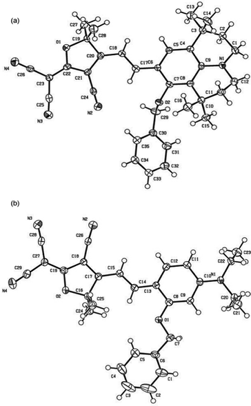 | ||
| Fig. 1 Ortep views of A (a) and B (b), showing 30% probability displacement ellipsoids. | ||
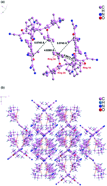 | ||
| Fig. 2 Crystal packing diagram of chromophoreA. | ||
| Compound reference | A | B |
| Chemical formula | C35H36N4O2 | C29H28N4O2 |
| Formula Mass | 544.68 | 464.55 |
| Crystal system | Monoclinic | Monoclinic |
| a/Å | 10.007(2) | 13.437(3) |
| b/Å | 19.208(5) | 8.1496(19) |
| c/Å | 15.433(3) | 23.189(6) |
| α (°) | 90.00 | 90.00 |
| β (°) | 99.743(4) | 96.921(4) |
| γ (°) | 90.00 | 90.00 |
| Unit cell volume/Å3 | 2923.4(12) | 2520.8(11) |
| T/K | 153(2) | 153(2) |
| Space group | P21/c | P21/n |
| No. of formula units per unit cell, Z | 4 | 4 |
| No. of reflections measured | 22987 | 19462 |
| No. of independent reflections | 6620 | 5771 |
| R int | 0.1325 | 0.0684 |
| Final R1 values (I > 2σ(I)) | 0.0618 | 0.0552 |
| Final wR(F2) values (I > 2σ(I)) | 0.0869 | 0.0942 |
| Final R1 values (all data) | 0.1432 | 0.1116 |
| Final wR(F2) values (all data) | 0.1003 | 0.1090 |
| Goodness of fit on F2 | 0.979 | 0.998 |
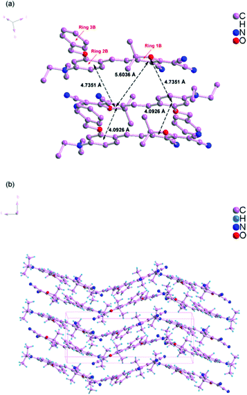 | ||
| Fig. 3 Crystal packing diagram of chromophoreB. | ||
The two chromophores have certain similarities and certain differences in their geometries. Similar to the acceptor structure, TCF units are almost planar, and the dihydrofuran rings and the carried three cyano groups are also almost coplanar. For the different donor parts, A and B have different planar structures with different dihedral angles between the donor and acceptor parts. In chromophoreB, the dihedral angle between the two planar parts (dihydrofuran ring (ring 1B) and benzene ring of C8–C13 (ring 2B)) is 9.9° after the introduction of the benzyloxy group. The average angles of benzene ring of C1–C6 (ring 3B) with ring 1B and ring 2B are 24.9 and 26.4°, respectively. From the general point, the chromophore B has an almost planar structure favorable for the excellent conjugation between the donor and acceptor parts and for the enhancement of the molecular NLO property. Nevertheless, A has a less coplanar structure than B due to the effect of twist coplanarity of the donor part. The dihedral angle between the two planar parts (dihydrofuran ring (ring 1A) and benzene ring of C4–C9 (ring 2A)) is 33.6° while that of B is 9.9°. The average angles of ring 1A with the locked six-member rings of N1–C1–C4–C9 and N1–C12–C8–C9 are 33.5 and 48.0°, and the benzene ring of C30–C35 (ring 3A) with ring 1A and ring 2A are 26.7 and 46.9°, respectively. In conclusion, A is less favorable for the efficient conjugation between the donor and acceptor parts. In terms of the negative effects, a lower coplanarity has an adverse effect on the electron transition and further impacts the first molecular hyperpolarizability; for the positive effects, a larger dihedral angle widens the distance between chromophores and weakens the dipole–dipole interactions between dipolar molecules, which benefit the macroscopic electro-optic efficiency.
The strong nonlinear optical chromophores have large dipole moments which lead to large dipole–dipole interactions. Such strong interactions induce an antiparallel packing of the dipolar molecules. These interactions play significant roles in determining the electro-optic efficiency.30,31 As Fig. 2 and 3 show, A and B form different packing due to different dipole–dipole interactions. A forms weak π–π interactions because of cross stacking of dipolar molecules. The results of PLATONS show the following three facts: (1) the π–π interactions, as shown in Fig. 2, mainly take place between the 3A ring and its neighboring rings 1A and 2A, with a corresponding centroid–centroid distance of 5.0745 Å and 4.9872 Å and a corresponding dihedral angle of 61.278° and 85.264°; (2) the π–π interactions also take place between the rings 3A, with a centroid–centroid distance of 4.8269 Å; (3) the interactions are found between donor rings 2A, with a centroid–centroid distance of 5.799 Å and a face-to-face distance of 4.536 Å. Unlike the molecular packing of A, the B form almost fully overlapped antiparallel dimers. As Fig. 3 shows, there are significant interlayer π–π interactions of donor parts (ring 2B) and acceptor parts (ring 1B). The results of PLATONS show the following three facts: (1) the closest two chromophores form antiparallel dimmer with a centroid–centroid distance of 4.0926 Å, corresponding to the face-to-face distances of 3.8137 Å and a dihedral of 9.867°; (2) the closer two chromophores also have π–π interactions with a centroid–centroid distance of 4.7351 Å, corresponding to the face-to-face distances of 4.0173 Å and a dihedral of 9.867°; (3) the π–π interactions also take place between the rings 1B, with a centroid–centroid distance of 5.6036 Å.
Apparently, crystal packing force of π–π interactions between donor parts and acceptor parts dominates the electrostatic interaction between the dimers in B. Based on the discussion above, the cross stacking of A obviously decreases the dipole–dipole interactions between molecules, while dimmers of B increase the dipole–dipole interactions.
The UV-Vis absorption spectra of the synthesized chromophores were measured to explore the differing electron-donating properties. Fig.4 displays the spectra of synthesized chromophores in three solvents of varying dielectric constants. The spectrum data are summarized in Table 2. Compared with chromophoreB, it may be seen from the Fig. 4a that the λmax of chromophoreA was shifted 31 nm to the longer wavelength of 618 nm, which was attributed to the fact that the 8-benzyloxy-1,1,7,7-tetramethyl-julolidinyl donor enhanced the electron-donating ability. For chromophoreA, two substituted –CH2– on aromatic ring results in about 10 nm bathochromic shift. The bathochromic shift is mainly attributed to the steric hindrance and the tension of rigid structure from the julolidinyl-based group. As the crystal analysis reveals, the rigid structure of the donor makes the double bond twisted and decreases the coplanarity of the conjugated system, which reduces the stability of the ground state, increasing the energy of the ground state. This phenomenon will decrease the transition energy of the conjugated system and lead to the bathochromic shift. The following DFT calculations of the energy gap of ground state and excited state will support our explanation of the bathochromic shift. Besides, the solvatochromic behavior was also explored to investigate the polarity of chromophores. When increasing the solvent dielectric constant, the charge-transfer band showed a solvatochromic red-shift. On the basis of our solvent studies using acetone, chloroform and dioxane, it was found that the absorption wavelength of chromophoresA and B in acetone and chloroform was almost the same. ChromophoresA and B showed bathochromic shifts of 30 nm and 28 nm from dioxane to chloroform, respectively, whereas 31 nm and 28 nm from dioxane to acetone. This confirms that chromophoreA is more polarizable than chromophoreB. We also found, from Fig. 4a to 4c, that the shoulder peaks increase. This phenomenon was due to the chromophores aggregation. The chromophores aggregated increasingly strongly, as the solvent dielectric constants decreased. The shoulder peak of chromophoreA is less obvious than in chromophoreB, which infers that chromophoreA is more difficult to aggregate than chromophoreB because of the steric hindrance and rigid structure of donor group.
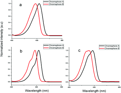 | ||
| Fig. 4 UV-Vis absorption spectra in acetone, chloroform and dioxane. | ||
| Chromophores | λ max a/nm | λ max b/nm | λ max c/nm | Δλd /nm | Δλe/nm |
|---|---|---|---|---|---|
| a λ max were measured in acetone. b λ max were measured in chloroform. c λ max were measured in dioxane. d Δλmax was the difference between λmaxa and λmaxc. e Δλmax was the difference between λmaxb and λmaxc. | |||||
| A | 618 | 617 | 587 | 31 | 30 |
| B | 587 | 587 | 559 | 28 | 28 |
In order to understand the ground-state polarization of the chromophores of different donors, the DFT calculations using Gaussian 03 were carried out at the hybrid B3LYP level by employing the split valence 6-31 g(d) basis set.32–34 In the case of chromophoresA and B, Fig. 5 depicts the electron density distribution of the HOMO and LUMO structures. This illustrates the density asymmetry of the ground and excited state electron along the dipolar axis of the chromophores. The HOMO and LUMO energy were calculated by DFT calculations as shown in Table 3. For chromophoreA, the effect of donor structure narrows the energy gap between the HOMO and LUMO energy with a ΔE value of 2.59 eV. By contrast, the ΔE value of B is 2.73 eV. It can be concluded that the LUMO energy of chromophoreB is 0.03 eV lager than A (−2.81 eV vs. −2.78 eV), while the HOMO energy of A is 0.11 eV larger than that of B (−5.40 eV vs. −5.51 eV). This may result from that the donor structure of A influences the HOMO energy to a greater extent than the LUMO energy. This result corresponds with the conclusion of UV-Vis spectra analysis that the steric hindrance and tension of the rigid structure from the julolidinyl-based donor increase the energy of the ground state more dramatically than that of excited state. This supports the idea that the complicated donor structures of chromophoreA increase the ground energy and enhance the electron-donating strength. As ΔE is reduced, the bathochromic shift happens from chromophoreB to chromophoreA.
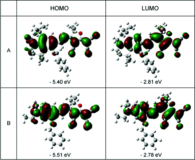 | ||
| Fig. 5 HOMO (left) and LUMO (right) surfaces of chromophoresA and B. | ||
| Chromophores | EHOMO/eV | ELUMO/eV | ΔEa/eV | β max b/10−30esu |
|---|---|---|---|---|
| a ΔE = ELUMO − EHOMO. b β values were calculated using gussian09 at B3LYP/6-31 g(d) level and the direction of the maximum value is directed along the charge transfer axis of the chromophores. | ||||
| A | −5.40 | −2.81 | 2.59 | 123.7 |
| B | −5.51 | −2.78 | 2.73 | 115.8 |
Further, the theoretical microscopic hyperpolarizability (β) is calculated by Gaussian 03. The β value is related to the substituent, steric hindrance, and intramolecular charge-transfer. Attributed to the stronger steric hindrance of donor and narrower energy gap between HOMO and LUMO, chromophoreA has a larger β value than chromophoreB (123.7 × 10⁻³⁰ esu vs. 115.8 × 10⁻³⁰ esu). This increment is not as large as we expect due to the less coplanarity of A than B, which is revealed in the crystal analysis.
To evaluate the NLO activity of chromophores, the polymer films containing chromophores were prepared to investigate the translating of large microscopic hyperpolarizability into large macroscopic EO response (r33). The EO activities (r33 values) of poled films were measured by Teng–Man simple reflection method at a wavelength of 1310 nm.35,36 The poling process was carried out at a temperature of 10 °C above the Tg of the polymer.
The r33 values of films containing chromophoreA (film-A) and B (film-B) were measured in varying loading density, as shown in Fig. 6. With the different loading density, film-A displayed larger r33 values than film-B. The r33 value of film-B was 16 pm V−1 when the chromophore loading density was increased to 25 wt%, which displays a saturated trend resulting from the strong inter-chromophore dipole–dipole interactions. When the loading density reached 30 wt%, the r33 value decreased to 13 pm V−1 because the negative effect of inter-chromophore dipole–dipole exceeded the positive effect of increasing chromophore loading density. For typical guest–host polymers, it is best to keep the chromophore loading density not more than 25 wt%, which is in accordance with the result of film-B.37,38 On the other hand, with the increase in chromophore loading density, the r33 value of film-A displayed a maximum of 36 pm V−1 at 40 wt% and then decreased at around 45 wt%. This saturated loading density of 40 wt% was much higher than the usual loading density of the guest–host doped NLO polymer materials. Even if 45 wt% of chromophoreA was loaded into the polymer matrix, no phase separation occurred in film-A. The high saturated loading density of film-A was probably attributed to the fact that the chromophore structure isolated the chromophores from each and thus reduced the inter-chromophore dipole–dipole interaction, thus improving the NLO effect at a much higher chromophore loading density level.
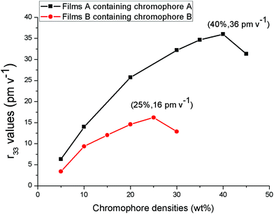 | ||
| Fig. 6 r33 values of NLO thin films as a function of chromophore loading densities. | ||
In order to understand the effect of chromophore structure on the NLO activity, the order parameter (Φ) was calculated by measuring UV-Vis absorption spectra (see Fig. 7). After the corona poling, the dipole moments of the chromophore moieties in the polymer were aligned, and the absorption curve decreased due to birefringence. From the absorption changes, the order parameter (Φ) for films can be calculated from the absorption changes according to the following equation: Φ = 1 – A1/A0 , in which A1 and A0 are the respective absorptions of the polymer films after and before corona poling.39 The order parameter (Φ) of poled films at a loading density of 10 wt% was calculated. The Φ value of film-A is 25.9%, while that of film-B is 15.4% (Fig. 4). The difference in the order parameter indicates that film-A containing chromophoreA has weaker interchromophore electrostatic interactions and is more easily poled than film-B, thus enhancing the macroscopic optical nonlinearities.
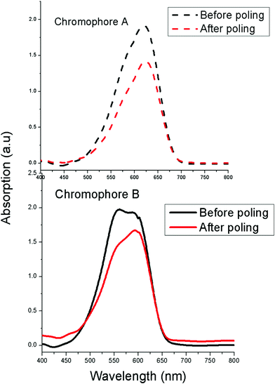 | ||
| Fig. 7 UV-Vis absorption spectra of E–O polymers before and after poling. | ||
The thermal properties of chromophoresA and B were explored by differential scanning calorimetry (DSC) and thermalgravimetric analysis (TGA), as shown in Table 4. Both the chromophoreA and B exhibited a highly crystalline characteristic with a melting point of 235 °C and 232 °C respectively. The decomposition temperatures (Td) of chromophoresA and B were 244 °C and 258 °C respectively. Due to the tension of the rigid structure of the donor, the Td of ChromophoreA is 14 °C lower than that of chromophoreB. Both chromophoresA and B are highly stable and may be widely applied in photonic device fabrications.
| Chromophores | T m/°C | T d/°C |
|---|---|---|
| A | 235 | 244 |
| B | 232 | 258 |
Conclusions
In summary, two new nonlinear optical (NLO) chromophores with different donors have been synthesized and systematically investigated to explore the effects of donors on the macroscopic optical nonlinearity. The single-crystal X-ray diffraction shows that chromophoreA with 8-benzyloxy-1,1,7,7-tetramethyl-formyl julolidinyl donating moiety displays weak electrostatic interactions in comparison with chromophoreB. The effects of bathochromic and solvatochromoic behavior on the UV-vis absorption were also investigated to prove the stronger electron donating ability and weaker intermolecular interactions of chromophoreA than B. The DFT calculation corresponds to the conclusions we made. In electro-optic activities, the doped film-A containing chromophoreA displays a maximum r33 value of 36 pm V−1 at the doping concentration of 40 wt%, while film-B containing chromophoreB shows a maximum r33 value of 16 pm V−1 at 25 wt%. Those outcomes indicate that the chromophoreA with the julolidinyl-based donor could efficiently reduce the interchromophore electrostatic interactions and enhance the macroscopic optical nonlinearity. This novel donor shows promising applications in nonlinear optical (NLO) chromophore synthesis.Experimental section
General
1HNMR spectra were determined by a Varian Gemini 300(300 MHZ) NMR spectrometer (tetramethylsilane as internal reference). The MS spectra were obtained on MALDI-TOF(Matrix Assisted Laser Desorption/Ionization of Flight) on BIFLEXIII(Broker Inc.) spectrometer. The UV-vis spectra were performed on Hitachi U2001 photo spectrometer. The TGA was determined by TA5000-2950TGA (TA co) with a heating rate of 10 °C min−1 under the protection of nitrogen. The single-crystal X-ray diffraction data were collected with the use of graphite-monochromatized Mo-Kα" radiation (λ = 0.71073 Å) at −180 °C on a Rigaku AFC10 diffractometer equipped with a Saturn CCD detector. All chemicals, commercially available, are used without further purification unless stated. The DMF was freshly distilled prior to its use. The 2-dicyanomethylene-3-cyano-4-methyl-2,5-dihydrofuran (TCF) acceptor was prepared according to the literature.12Syntheses
Poling and r33 measurements
To study the EO property derived from the chromophores, guest–host polymers were prepared by formulating chromophoresA and B into amorphous polycarbonate (APC) using dibromomethane (CH2Br2) as the solvent. The resulting solutions were filtered through a 0.22 μm Teflon membrane filter and spin-coated onto indium tin oxide (ITO) glass substrates. Films of doped polymers were baked in a vacuum oven at 40 °C to remove the residual solvent. The poling process was carried out at a temperature of about 10 °C above the Tg of the polymer. The r33 values were measured using Teng-Man simple reflection technique at the wavelength of 1310 nm.Acknowledgements
We are grateful to the Directional Program of the Chinese Academy of Sciences (KJCX2.YW.H02) and the National Basic Research Program of China (973 Program, Grant No.2006CB933000) for financial support.References
- M. Lee, H. E. Katz, C. Erben, D. M. Gill, P. Gopalan, J. D. Heber and D. J. McGee, Science, 2002, 298, 1401 CrossRef CAS.
- S. R. Marder, B. Kippelen, A. K. Y. Jen and N. Peyghambarian, Nature, 1997, 388, 845 CrossRef CAS.
- J. H. Wulbern, S. Prorok, J. Hampe, A. Petrov, M. Eich, J. D. Luo, A. K. Y. Jen, M. Jenett and A. Jacob, Opt. Lett., 2010, 35, 2753 Search PubMed.
- C. Zhang, L. R. Dalton, M. C. Oh, H. Zhang and W. H. Steier, Chem. Mater., 2001, 13, 3043 CrossRef CAS.
- M. Hochberg, T. Baehr-Jones, G. X. Wang, M. Shearn, K. Harvard, J. D. Luo, B. Q. Chen, Z. W. Shi, R. Lawson, P. Sullivan, A. K. Y. Jen, L. Dalton and A. Scherer, Nat. Mater., 2006, 5, 703 CrossRef CAS.
- K. A. Firestone, P. Reid, R. Lawson, S. H. Jang and L. R. Dalton, Inorg. Chim. Acta, 2004, 357, 3957 CrossRef CAS.
- C. W. Spangler, M. Q. He, E. G. Nickel, J. Laquindanum, L. R. Dalton, N. S. Tang and R. Hellwarth, Mol. Cryst. Liq. Cryst. Sci. Technol., Sect. A, 1994, 240, 17 Search PubMed.
- D. H. Bale, B. E. Eichinger, W. K. Liang, X. S. Li, L. R. Dalton, B. H. Robinson and P. J. Reid, J. Phys. Chem. B, 2011, 115, 3505 Search PubMed.
- L. R. Dalton, J. Phys.: Condens. Matter, 2003, 15, R897 CrossRef CAS.
- L. R. Dalton, D. Lao, B. C. Olbricht, S. Benight, D. H. Bale, J. A. Davies, T. Ewy, S. R. Hammond and P. A. Sullivan, Opt. Mater., 2010, 32, 658 Search PubMed.
- Y. J. Cheng, J. D. Luo, S. Hau, D. H. Bale, T. D. Kim, Z. W. Shi, D. B. Lao, N. M. Tucker, Y. Q. Tian, L. R. Dalton, P. J. Reid and A. K. Y. Jen, Chem. Mater., 2007, 19, 1154 CrossRef CAS.
- M. Q. He, T. M. Leslie and J. A. Sinicropi, Chem. Mater., 2002, 14, 2393 CrossRef CAS.
- S. H. Jang, J. D. Luo, N. M. Tucker, A. Leclercq, E. Zojer, M. A. Haller, T. D. Kim, J. W. Kang, K. Firestone, D. Bale, D. Lao, J. B. Benedict, D. Cohen, W. Kaminsky, B. Kahr, J. L. Bredas, P. Reid, L. R. Dalton and A. K. Y. Jen, Chem. Mater., 2006, 18, 2982 CrossRef CAS.
- J. A. Davies, A. Elangovan, P. A. Sullivan, B. C. Olbricht, D. H. Bale, T. R. Ewy, C. M. Isborn, B. E. Eichinger, B. H. Robinson, P. J. Reid, X. Li and L. R. Dalton, J. Am. Chem. Soc., 2008, 130, 10565 CrossRef CAS.
- S. Li, M. Li, J. G. Qin, M. L. Tong, X. M. Chen, T. Liu, Y. Fu, S. X. Wu and Z. M. Su, CrystEngComm, 2009, 11, 589 RSC.
- Y. Le Fur, R. Masse and J. F. Nicoud, New J. Chem., 1998, 22, 159 RSC.
- J. Chiffre, F. Averseng, G. G. A. Balavoine, J. C. Daran, G. Iftime, P. G. Lacroix, E. Manoury and K. Nakatani, Eur. J. Inorg. Chem., 2001, 2221 CrossRef CAS.
- O. P. Kwon, M. Jazbinsek, H. Yun, J. I. Seo, J. Y. Seo, S. J. Kwon, Y. S. Lee and P. Gunter, CrystEngComm, 2009, 11, 1541 RSC.
- S. J. Kwon, C. Hunziker, O. P. Kwon, M. Jazbinsek and P. Gunter, Cryst. Growth Des., 2009, 9, 2512 Search PubMed.
- Y. Liao, B. E. Eichinger, K. A. Firestone, M. Haller, J. D. Luo, W. Kaminsky, J. B. Benedict, P. J. Reid, A. K. Y. Jen, L. R. Dalton and B. H. Robinson, J. Am. Chem. Soc., 2005, 127, 2758 CrossRef CAS.
- B. Ruiz, B. J. Coe, R. Gianotti, V. Gramlich, M. Jazbinsek and P. Gunter, CrystEngComm, 2007, 9, 772 RSC.
- X. M. Zhang, I. Aoki, X. Q. Piao, S. Inoue, H. Tazawa, S. Yokoyama and A. Otomo, Tetrahedron Lett., 2010, 51, 5873 Search PubMed.
- K. Schmidt, S. Barlow, A. Leclercq, E. Zojer, S. H. Jang, S. R. Marder, A. K. Y. Jen and J. L. Bredas, J. Mater. Chem., 2007, 17, 2944 RSC.
- C. G. Wang and L. R. Dalton, Tetrahedron Lett., 2000, 41, 617 Search PubMed.
- B. J. Coe, S. P. Foxon, E. C. Harper, J. A. Harris, M. Helliwell, J. Raftery, I. Asselberghs, K. Clays, E. Franz, B. S. Brunschwig and A. G. Fitch, Dyes Pigm., 2009, 82, 171 Search PubMed.
- A. Jen, X. H. Zhou, J. Davies, S. Huang, J. D. Luo, Z. W. Shi, B. Polishak, Y. J. Cheng, T. D. Kim and L. Johnson, J. Mater. Chem., 2011, 21, 4437 RSC.
- Z. Li, Z. A. Li, L. Wang, B. Xiong, C. Ye and J. G. Qin, Dyes Pigm., 2010, 84, 134 CrossRef CAS.
- Y. P. Cui, Q. Q. Li, C. G. Lu, J. Zhu, E. Fu, C. Zhong, S. Y. Li, J. G. Qin and Z. Li, J Phys Chem B, 2008, 112, 4545 CrossRef CAS.
- W. Gong, Q. Q. Li, Z. Li, C. G. Lu, J. Zhu, S. Y. Li, J. W. Yang, Y. P. Cui and J. G. Qin, J. Phys. Chem. B, 2006, 110, 10241 CrossRef CAS.
- B. H. Robinson and L. R. Dalton, J. Phys. Chem. A, 2000, 104, 4785 CrossRef CAS.
- Y. Q. Shi, C. Zhang, H. Zhang, J. H. Bechtel, L. R. Dalton, B. H. Robinson and W. H. Steier, Science, 2000, 288, 119 CrossRef CAS.
- R. M. Dickson and A. D. Becke, J. Chem. Phys., 1993, 99, 3898 CrossRef CAS.
- M. J. Frisch, G. W. Trucks, H. B. Schlegel, G. E. Scuseria, M. A. Robb, J. R. Cheeseman, J. A. Montgomery, T. Vreven, K. N. Kudin, J. C. Burant, J. M. Millam, S. S. Iyengar, J. Tomasi, V. Barone, B. Mennucci, M. Cossi, G. Scalmani, N. Rega, G. A. Petersson, H. Nakatsuji, M. Hada, M. Ehara, K. Toyota, R. Fukuda, J. Hasegawa, M. Ishida, T. Nakajima, Y. Honda, O. Kitao, H. Nakai, M. Klene, X. Li, J. E. Knox, H. P. Hratchian, J. B. Cross, C. Adamo, J. Jaramillo, R. Gomperts, R. E. Stratmann, O. Yazyev, A. J. Austin, R. Cammi, C. Pomelli, J. W. Ochterski, P. Y. Ayala, K. Morokuma, G. A. Voth, P. Salvador, J. J. Dannenberg, V. G. Zakrzewski, S. Dapprich, A. D. Daniels, M. C. Strain, O. Farkas, D. K. Malick, A. D. Rabuck, K. Raghavachari, J. B. Foresman, J. V. Ortiz, Q. Cui, A. G. Baboul, S. Clifford, J. Cioslowski, B. B. Stefanov, G. Liu, A. Liashenko, P. Piskorz, I. Ko-maromi, R. L. Martin, D. J. Fox, T. Keith, M. A. Al-Laham, C. Y. Peng, A. Nanayakkara, M. Challacombe, P. M. W. Gill, B. Johnson, W. Chen, M. W. Wong, C. Gonzalez, J. A.. Pople, Gaussian 03, Gaussian, Inc., Pittsburgh, PA, 2003 Search PubMed.
- C. Lee and R. G. Parr, Phys. Rev. A: At., Mol., Opt. Phys., 1990, 42, 193 Search PubMed.
- C. C. Teng and H. T. Man, Appl. Phys. Lett., 1990, 56, 1734 CrossRef CAS.
- D. H. Park, C. H. Lee and W. N. Herman, Opt. Express, 2006, 14, 8866 CrossRef.
- J. K. Gao, Y. J. Cui, J. C. Yu, W. X. Lin, Z. Y. Wang and G. D. Qian, J. Mater. Chem., 2011, 21, 3197 RSC.
- L. Dalton, In Adv Polym Sci; Springer-Verlag Berlin: Berlin, 2002, 158, 1 Search PubMed.
- V. Rodriguez, F. Adamietz, L. Sanguinet, T. Buffeteau and C. Sourisseau, J. Phys. Chem. B, 2003, 107, 9736 CrossRef CAS.
Footnote |
| † CCDC reference numbers 837247 and 837248. For crystallographic data in CIF or other electronic format see DOI: 10.1039/c1ra00838b |
| This journal is © The Royal Society of Chemistry 2012 |
