Cobalt hydrotalcite for the steam reforming of ethanol with scarce carbon production
Raúl
Espinal
a,
Elena
Taboada
a,
Elies
Molins
b,
Ricardo J.
Chimentao
c,
Francesc
Medina
c and
Jordi
Llorca
*a
aInstitut de Tècniques Energètiques and Centre de Recerca en Nanoenginyeria, Universitat Politècnica de Catalunya (UPC), Av. Diagonal, 647, 08028 Barcelona, Spain
bInstitut de Ciència de Materials de Barcelona (ICMAB-CSIC), Campus UAB, Bellaterra, 08193, Spain
cEscola Tècnica Superior d’Enginyeria Química, Universitat Rovira i Virgili (URV), Av. Països Catalans, 26, Tarragona, 43007, Spain
First published on 14th February 2012
Abstract
Co/Mg/Al hydrotalcite-type catalysts have been loaded onto ceramic honeycombs and tested in the ethanol steam reforming (ESR) reaction for producing hydrogen under practical conditions. In contrast with previously reported cobalt-based systems, the formation of carbon was scarce. This has been ascribed to the unique formation of traces of metallic cobalt particles under reaction conditions, as inferred from HRTEM, magnetic measurements, and in situ X-ray photoelectron spectroscopy (XPS) experiments. The best catalytic performance has been exhibited by the catalyst derived from the hydrotalcite with a Co:Mg:Al molar ratio of 1![[thin space (1/6-em)]](https://www.rsc.org/images/entities/char_2009.gif) :
:![[thin space (1/6-em)]](https://www.rsc.org/images/entities/char_2009.gif) 2
2![[thin space (1/6-em)]](https://www.rsc.org/images/entities/char_2009.gif) :
:![[thin space (1/6-em)]](https://www.rsc.org/images/entities/char_2009.gif) 1, where CoAl spinel and CoO strongly interacting with MgO phases have been identified.
1, where CoAl spinel and CoO strongly interacting with MgO phases have been identified.
1. Introduction
Ethanol is nowadays a well-established source of hydrogen via catalytic steam reforming, oxidative reforming or partial oxidation processes. Numerous reviews have been published in the last years, covering both catalytic aspects and fuel reformer concepts.1–5 Ethanol has the advantage over other conventional substrates such as natural gas, gasoline or liquefied petroleum gas (LPG) that it is readily available, easy to obtain from biomass, almost CO2-neutral (bioethanol), safe to handle and can be processed at low temperature to obtain hydrogen. Among the different processes for hydrogen production, including those outlined above, as well as CO2 sorption enhanced routes, ethanol steam reforming (ESR) is the simplest for implementation and yields more hydrogen, since part of it comes from water (eqn (1)).| C2H5OH + 3 H2O → 6 H2 + 2 CO2 | (1) |
The drawback of ESR, however, is thermal management. Steam reforming reactions are strongly endothermic and require a continuous supply of heat. In ethanol reformers, this can be provided by a combination of direct and catalytic combustion of ethanol and by burning the anode off-gas of a fuel cell.4,6 Therefore, it is desirable to develop catalysts for low-temperature ESR to optimize thermal management in addition to build long life and safe reformers that can be used for portable applications. A survey of the literature reveals that noble metal-based catalysts perform well for ESR.1–3,7,8 They are stable and exhibit high activity, but only at high temperature (> 900 K). The reason is that the reaction mechanism involves the decomposition of ethanol at low temperature into a mixture of hydrogen, carbon monoxide and methane (eqn (2)), followed by the water gas shift reaction (WGS) at intermediate temperature (eqn (3)) and, finally, the steam reforming of methane at high temperature (eqn (4)).9
| C2H5OH → H2 + CO + CH4 | (2) |
 | (3) |
 | (4) |
In order to carry out ESR at low temperature, a different type of catalyst is required; in particular, a catalyst that does not yield methane as an intermediate species in the reaction mechanism, which can only be reformed at high temperature. Relatively inexpensive cobalt catalysts fulfil this requirement.10–32 Over cobalt-based catalysts, ethanol is first dehydrogenated into a mixture of hydrogen and acetaldehyde (eqn (5)), and acetaldehyde reacts with steam to yield mainly hydrogen and carbon oxides (eqn (6)).33,34 Given the lower temperature of the overall process, the WGS equilibrium (eqn (3)) favors the hydrogen yield.
| C2H5OH → H2 + CH3CHO | (5) |
| CH3CHO + H2O → 3 H2 + 2 CO | (6) |
However, and in contrast to noble metal-based systems, cobalt catalysts suffer from severe deactivation during ESR due to extensive carbon deposition. In situ infrared spectroscopy experiments,35in situ magnetic measurements33,36 and in situ X-ray photoelectron spectroscopy experiments13 have revealed that Co metal particles are formed under reaction conditions, which rapidly detach from the catalyst support and originate carbon nanotubes and carbon nanofibers. At the same time, methane selectivity increases at the expense of the reforming products (H2 and COx) and the initial catalytic performance is not recovered after regeneration. In this work, we report the catalytic performance of ceramic honeycombs coated with Co/Mg/Al hydrotalcites for performing ESR at moderate temperature with scarce carbon formation. Hydrotalcite precursors have already been used for the synthesis of catalysts suitable for ethanol reforming reactions. In most cases nickel hydrotalcites have been used for ESR, and only a few examples of cobalt hydrotalcites exist, but no details about stability and coke formation have been reported under high ethanol loads.37–39
A detailed characterization has been carried out by using X-ray diffraction (XRD), scanning electron microscopy (SEM-EDX), high resolution transmission electron microscopy (HRTEM), magnetic measurements and temperature-programmed techniques (TGA, DSC and TPR) as well as in situ X-ray photoelectron spectroscopy (XPS). No metallic cobalt was detected by XRD or HRTEM and only traces of metallic cobalt were detected in some cases by magnetic measurements and XPS, inferring that not only metallic cobalt is catalytically active for ESR, but also cobalt cations. We have used catalytic honeycombs instead of conventional powdered or pelletized samples because they are robust, easy to scale up and replace, and offer homogeneous flow distribution patterns with low pressure drop, which constitute critical aspects for the development of fuel reformers.4,11,14,40,41
2. Experimental
2.1 Catalyst preparation
Co/Mg/Al hydrotalcites with Co:Mg:Al molar ratios of 0.5![[thin space (1/6-em)]](https://www.rsc.org/images/entities/char_2009.gif) :
:![[thin space (1/6-em)]](https://www.rsc.org/images/entities/char_2009.gif) 2.5
2.5![[thin space (1/6-em)]](https://www.rsc.org/images/entities/char_2009.gif) :
:![[thin space (1/6-em)]](https://www.rsc.org/images/entities/char_2009.gif) 1, 1
1, 1![[thin space (1/6-em)]](https://www.rsc.org/images/entities/char_2009.gif) :
:![[thin space (1/6-em)]](https://www.rsc.org/images/entities/char_2009.gif) 2
2![[thin space (1/6-em)]](https://www.rsc.org/images/entities/char_2009.gif) :
:![[thin space (1/6-em)]](https://www.rsc.org/images/entities/char_2009.gif) 1 and 2
1 and 2![[thin space (1/6-em)]](https://www.rsc.org/images/entities/char_2009.gif) :
:![[thin space (1/6-em)]](https://www.rsc.org/images/entities/char_2009.gif) 1
1![[thin space (1/6-em)]](https://www.rsc.org/images/entities/char_2009.gif) :
:![[thin space (1/6-em)]](https://www.rsc.org/images/entities/char_2009.gif) 1 were prepared by co-precipitation at constant pH (10 ± 0.2) by adding an aqueous solution of NaOH/Na2CO3 (2 M) onto an aqueous solution of CoCl2·6H2O, Mg(NO3)2·6H2O and Al(NO3)3·9H2O. Both solutions were mixed dropwise under stirring at 298 K. The slurry was aged at 298 K for 15 h under vigorous stirring and the resulting precipitate was filtered and thoroughly washed with deionized water. The solids were dried at 373 K for 18 h to yield the as-synthesized samples. The co-precipitation method allows preparing hydrotalcites with a given metallic content, since there is no loss of metallic salt during the process. In this sense, these hydrotalcites have the nominal formulae [CoMg5Al2(OH)16]CO3·4H2O, [Co2Mg4Al2(OH)16]CO3·4H2O and [Co4Mg2Al2(OH)16]CO3·4H2O and are named from now on as 0.5/2.5/1_as, 1/2/1_as and 2/1/1_as, respectively, where as stands for as-synthesized.
1 were prepared by co-precipitation at constant pH (10 ± 0.2) by adding an aqueous solution of NaOH/Na2CO3 (2 M) onto an aqueous solution of CoCl2·6H2O, Mg(NO3)2·6H2O and Al(NO3)3·9H2O. Both solutions were mixed dropwise under stirring at 298 K. The slurry was aged at 298 K for 15 h under vigorous stirring and the resulting precipitate was filtered and thoroughly washed with deionized water. The solids were dried at 373 K for 18 h to yield the as-synthesized samples. The co-precipitation method allows preparing hydrotalcites with a given metallic content, since there is no loss of metallic salt during the process. In this sense, these hydrotalcites have the nominal formulae [CoMg5Al2(OH)16]CO3·4H2O, [Co2Mg4Al2(OH)16]CO3·4H2O and [Co4Mg2Al2(OH)16]CO3·4H2O and are named from now on as 0.5/2.5/1_as, 1/2/1_as and 2/1/1_as, respectively, where as stands for as-synthesized.
2.2 Catalytic honeycombs preparation
The as-synthesized hydrotalcites were deposited onto cordierite supports (400 cells per square inch) by the washcoating method. Two different commercial honeycombs were used from Rauschert and Corning companies, with similar chemical composition (Al3Mg2AlSi5O18). They were cut into cylindrical pieces of 1.8 cm in diameter and 2 cm long. Two different binding agents were tested for coating the honeycombs with the as-synthesized hydrotalcites: a 2![[thin space (1/6-em)]](https://www.rsc.org/images/entities/char_2009.gif) :
:![[thin space (1/6-em)]](https://www.rsc.org/images/entities/char_2009.gif) 1 molar mixture of methoxyethanol and monoethanolamine42 and a 5
1 molar mixture of methoxyethanol and monoethanolamine42 and a 5![[thin space (1/6-em)]](https://www.rsc.org/images/entities/char_2009.gif) :
:![[thin space (1/6-em)]](https://www.rsc.org/images/entities/char_2009.gif) 1 molar mixture of polyvinyl alcohol (PVA) and acetic acid.43 The resulting catalytic honeycombs were dried at 363 K for 2 h and calcined at 823 K for 3 h. The adherence of the catalytic coatings onto the cordierite walls was checked by immersing the catalytic honeycombs in an ultrasonic bath and monitoring the weight loss for 5, 10, 15, 20, 25 and 30 s. Significant differences were encountered, being more stable the catalytic honeycombs prepared with the PVA binding agent over Rauschert substrates (22.5 wt.% loss after 30 s of ultrasound exposure). To better characterize the microstructure of the catalytic coatings, the hydrotalcites were calcined in powder form as well, following exactly the same procedure. These samples were named 0.5/2.5/1_calc, 1/2/1_calc and 2/1/1_calc.
1 molar mixture of polyvinyl alcohol (PVA) and acetic acid.43 The resulting catalytic honeycombs were dried at 363 K for 2 h and calcined at 823 K for 3 h. The adherence of the catalytic coatings onto the cordierite walls was checked by immersing the catalytic honeycombs in an ultrasonic bath and monitoring the weight loss for 5, 10, 15, 20, 25 and 30 s. Significant differences were encountered, being more stable the catalytic honeycombs prepared with the PVA binding agent over Rauschert substrates (22.5 wt.% loss after 30 s of ultrasound exposure). To better characterize the microstructure of the catalytic coatings, the hydrotalcites were calcined in powder form as well, following exactly the same procedure. These samples were named 0.5/2.5/1_calc, 1/2/1_calc and 2/1/1_calc.
2.3 Catalytic tests
Ethanol steam reforming was carried out in the temperature range 523–823 K at atmospheric pressure in a tubular stainless-steel reactor over the catalytic honeycombs without any pretreatment. The reaction was tested with a gaseous H2O:CH3CH2OH = 4![[thin space (1/6-em)]](https://www.rsc.org/images/entities/char_2009.gif) :
:![[thin space (1/6-em)]](https://www.rsc.org/images/entities/char_2009.gif) 1 molar mixture (steam to carbon, S/C = 2) provided directly with a Knauer Smartline HPLC pump (the liquid mixture was vaporized at 450 K before entering the reactor), or by using a nitrogen stream saturated with the reactants. VHSV (volume hourly space velocity) values ranged from 420 to 660 h−1 and W/F values ranged from 390 to104 g min mol−1 EtOH. The reactor effluent was monitored on-line every 5 min by gas chromatography (Agilent 3000 A) using MS 5 Å, Plot U and Stabilwax columns. Stability tests were conducted at 823 K with pure liquid mixture. On the other hand, 0.5/2.5/1_calc, 1/2/1_calc and 2/1/1_calc powder samples were subjected to ESR at 823 K for 7 h in a similar manner and the resulting samples were labeled as 0.5/2.5/1_reac, 1/2/1_reac and 2/1/1_reac and used for characterization.
1 molar mixture (steam to carbon, S/C = 2) provided directly with a Knauer Smartline HPLC pump (the liquid mixture was vaporized at 450 K before entering the reactor), or by using a nitrogen stream saturated with the reactants. VHSV (volume hourly space velocity) values ranged from 420 to 660 h−1 and W/F values ranged from 390 to104 g min mol−1 EtOH. The reactor effluent was monitored on-line every 5 min by gas chromatography (Agilent 3000 A) using MS 5 Å, Plot U and Stabilwax columns. Stability tests were conducted at 823 K with pure liquid mixture. On the other hand, 0.5/2.5/1_calc, 1/2/1_calc and 2/1/1_calc powder samples were subjected to ESR at 823 K for 7 h in a similar manner and the resulting samples were labeled as 0.5/2.5/1_reac, 1/2/1_reac and 2/1/1_reac and used for characterization.
2.4 Characterization techniques
Powder X-ray diffraction (XRD) patterns of the powder catalysts were collected between 5 and 70° 2θ, at a step width of 0.02° and a step time of 1 s using a Bruker D8 instrument equipped with a Cu target and a graphite monochromator. Magnetization (M) vs. applied magnetic field (H) (at 5 and 298 K) and ZFC-FC curves (at 50 Oe) were measured with a superconducting quantum interference device (SQUID) magnetometer (Quantum Design MPMS5XL, USA). A given amount of powder was confined in a gelatin capsule (of known mass) and pressed with a given amount of cotton to avoid the powder from moving during the measurement. The diamagnetic contribution of the capsule and the cotton was subtracted from the total magnetization (mtotal) as follows: | (7) |
Thermogravimetric analysis (TGA) was accomplished with a Netzsch STA 449 F1 Jupiter analyzer. Differential scanning calorimetry (DSC) was performed on a DSC 8500 Perkin Elmer. Heating rate was fixed at 10 K min−1, from room temperature to 1173 K, both under argon and under air. Temperature programmed reduction (TPR) was performed in a Catalyst Analyzer BELCAT-M (BEL Japan, Inc.), equipped with a water trap and a thermal conductivity detector (TCD). Prior to each TPR run, samples were heated up to 823 K (10 K min−1) and cooled down to room temperature under argon. Then they were analyzed by heating up to 1173 K (10 K min−1) using hydrogen (10 vol% in argon) under a flow rate of 30 ml min−1. The morphologies of the catalysts were observed by SEM with a Neon40 Crossbeam Station (Zeiss) equipped with a field emission electron source and an energy-dispersive X-ray spectrometer (EDX). A small portion of each sample powder was deposited on a metallic disk holder and covered with a thin gold layer before SEM analysis. High resolution transmission electron microscopy (HRTEM) was conducted on a JEOL 2010F microscope operating at 200 kV and equipped with a field emission electron source. The point-to-point resolution of the instrument was 0.19 nm and the resolution between lines was 0.14 nm. Samples were dispersed onto holey-carbon grids from alcohol suspensions.
Infrared spectra were collected using a Shimadzu FTIR 8400S spectrometer (resolution 2 cm−1). X-ray photoelectron spectroscopy (XPS) was performed with a SPECS system equipped with an Al anode XR50 source operating at 150 W and a Phoibos 150 MCD-9 detector. Sample powders were pressed to pellets and then fixed into a special sample holder (no glue was used). Spectra were recorded with pass energy of 25 eV at 0.1 eV steps at a pressure below 6 × 10⁻⁹ mbar; binding energies were referred to the adventitious C 1s signal. The apparatus was equipped with an additional high pressure cell (HPC-20) for in situ treatments that, in addition to calcination and reduction treatments, allowed reproducing ESR conditions, too. An Ametek mass spectrometer connected to the high pressure cell was used to monitor the reaction products to ascertain that the in situ XPS experiments reproduced those performed over the catalytic honeycombs during the conventional ESR tests. Experiments were carried out at 1 bar and temperature was provided with an infrared source and was measured directly on the sample holder by a thermocouple. After each in situ treatment, samples were transferred from the reaction cell to the analysis chamber under high vacuum (less than 5 × 10⁻⁷ Pa).
The characterization of sample 1/2/1 was deeper in detail since its catalytic activity and selectivity towards hydrogen was the best of the three studied samples.
3. Results and discussion
3.1 As-synthesized samples
The peaks in the X-ray diffractogram of the as-synthesized samples could be indexed both to the Mg/Al and Co/Al hydrotalcite phases (XRD patterns 00-020-065844 and 00-051-0045,45 respectively; see Fig. 1). Since there is only one set of peaks we understand the samples are composed of Co/Mg/Al hydrotalcites. It has been reported that the crystallinity of MgAl hydrotalcites dramatically degrades due to the substitution of magnesium by cobalt ions.46 In particular, the c parameter, related to the thickness of the interlayer distance in hydrotalcites (c = 3 × d (003)), decreases as the Co/Mg ratio is increased, because of a decay in electrostatic attraction between the brucite layer positive charges and interlayer negative charges.47 In this sense, the first three peaks of the hydrotalcite diffractograms, indexed to 006, 0012 and 0018 reflections, are shifted to higher angles as the amount of cobalt increases. Sample 1/2/1_as is not only the most crystalline (narrowest peaks), but also bears these peaks at lower angles than the other two, indicating that cobalt ions might have not completely substituted magnesium cations within the brucite-like layers.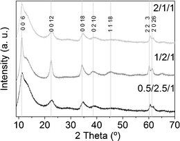 | ||
| Fig. 1 X-Ray diffractograms of as-synthesized hydrotalcites. The hump centered around 13° is due to the sample holder. | ||
IR spectra (not shown) also contain the bands corresponding to the hydrotalcite bonds: a broad band centered at 3458 cm−1 and a small one at 1618 cm−1 due to hydroxyl ions and physically adsorbed water molecules, respectively; narrow bands around 1387 cm−1 corresponding to carbonate ions; and bands at low wavenumber 435, 625 and 637 cm−1 associated to Al–O, Co–O and Mg–O vibrations, respectively.48
The morphology and structure of sample 1/2/1_as was studied by scanning and transmission electron microscopies (Fig. 2). SEM showed a homogeneous and laminar material, as expected for hydrotalcites. The energy dispersive X-ray detector identified the presence of carbon, oxygen, cobalt, magnesium and aluminum with a molar ratio of Co:Mg:Al = 26![[thin space (1/6-em)]](https://www.rsc.org/images/entities/char_2009.gif) :
:![[thin space (1/6-em)]](https://www.rsc.org/images/entities/char_2009.gif) 50
50![[thin space (1/6-em)]](https://www.rsc.org/images/entities/char_2009.gif) :
:![[thin space (1/6-em)]](https://www.rsc.org/images/entities/char_2009.gif) 24, very close to the nominal value of 25
24, very close to the nominal value of 25![[thin space (1/6-em)]](https://www.rsc.org/images/entities/char_2009.gif) :
:![[thin space (1/6-em)]](https://www.rsc.org/images/entities/char_2009.gif) 50
50![[thin space (1/6-em)]](https://www.rsc.org/images/entities/char_2009.gif) :
:![[thin space (1/6-em)]](https://www.rsc.org/images/entities/char_2009.gif) 25. A closer view was facilitated by TEM. The sample bears sheet-like particles (average length = 62 ± 13 nm), stacked in bunches.
25. A closer view was facilitated by TEM. The sample bears sheet-like particles (average length = 62 ± 13 nm), stacked in bunches.
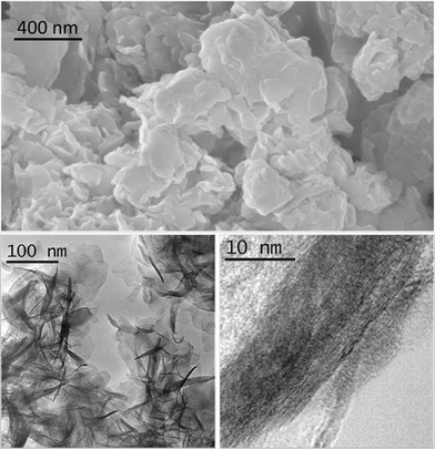 | ||
| Fig. 2 SEM image (above) and TEM images (below) of sample 1/2/1_as. | ||
The as-synthesized samples showed paramagnetic (PM) behavior at room temperature and slightly superparamagnetic (SPM) at 5 K (Fig. 3). The profile of the zero field cooled–field cooled (ZFC-FC) curves is characteristic of paramagnetic materials, with no maximum in the ZFC curve. The inverse of molar susceptibility of cobalt (χM; emu mol−1 Oe−1) vs. temperature obeys the Curie–Weiss (7) law over 50 K (see Fig. 3, right below).
 | (8) |
 | (9) |
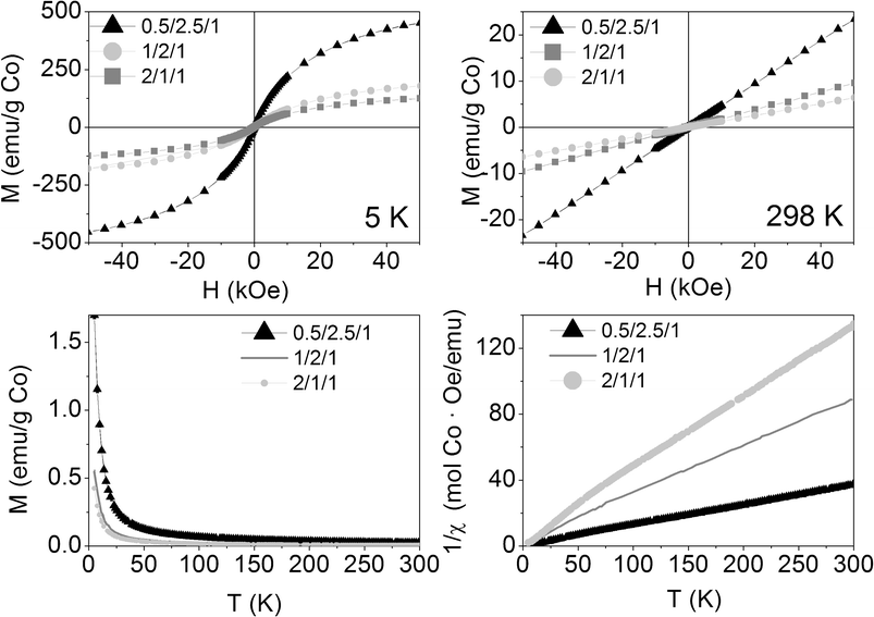 | ||
| Fig. 3 Magnetization curves vs. applied magnetic field at 5 K and 298 K (above), magnetization vs. temperature at 50 Oe (below left) and inverse of susceptibility vs. temperature at 50 Oe (below right) of the as-synthesized samples. | ||
The Curie constant is, in turn, related to the effective magnetic moment (μeff):
 | (10) |
![[thin space (1/6-em)]](https://www.rsc.org/images/entities/char_2009.gif) :
:![[thin space (1/6-em)]](https://www.rsc.org/images/entities/char_2009.gif) 1 molar ratio hydrotalcite were encountered.
1 molar ratio hydrotalcite were encountered.
3.2 Calcined samples
The ethanol steam reforming reaction was carried out over catalytic honeycombs calcined at 823 K since it is well known that thermal decomposition of Mg–Al hydrotalcites leads to a well dispersed mixture of magnesium and aluminum oxides with basic properties, which are favorable for the dehydrogenation of ethanol into acetaldehyde, the first step of ESR over Co-based systems (eqn (5)). For that reason, hydrotalcites were thoroughly characterized after calcination at this temperature.The calcination process was followed by thermogravimetric analysis (TGA) and differential scanning calorimetry (DSC). TGA profiles were derived to get the differential thermogravimetric (DTG) profiles for a better detection of the mass losses. Panels a, b and c in Fig. 4 show these profiles of the three as-synthesized hydrotalcites. Furthermore, some of the analyses were coupled to a mass spectrometer, in order to identify the nature of the evolved species. As can be observed in Fig. 4, the three as-synthesized samples showed similar DTG profiles in argon: the first peak centered at 398 K was assigned to the desorption of physisorbed water, the one at 437 K corresponded to the decomposition of interlayer water and a small amount of carbonate ions in the form of carbon dioxide, and the overlapped peaks centered around 560 K and 627 K indicated the loss of interlayer anions (carbonates in the form of carbon dioxide, nitrate in the form of nitrous oxide and hydroxyl ions in the form of water). Further dehydroxylation of the brucite-like layers was accomplished mainly up to 900 K (as observed by mass spectrometry) but kept on slowly up to 1173 K. This profile for hydrotalcite thermal decomposition matches published results by other groups.51,52 The endothermic peak observed in the DSC profile above 900 K goes together with a drastic drop in the water evolved, as observed by mass spectrometry. Chmielarz et al. observed the evolution of molecular oxygen at this temperature range, for what they proposed that part of Co2+ cations were firstly oxidized to Co3+ by NOx species, and then the reverse process occurred with oxygen evolving.52 As we do not observe oxygen evolving, in either species, we understood the endothermic process as a crystalline restructuration of the material from hydrotalcite to spinel (see XRD data below), after dehydroxylation of the brucite-like structure. The percentages of mass losses in each stage are summarized in Table 1. The amounts of mass losses are close to those expected from hydrotalcites with nominal formula: [CoxMg6-xAl2(OH)16]CO3·4H2O, with x = 0.5, 1 and 2 and the mass left at 1173 K is close to the theoretical remaining mass of metal oxides (CoxMg6-xAl2)O9. The samples decomposed at the same temperature under air (see Fig. 5). The most relevant difference between air and argon experiments is the lack of a peak in the DSC profiles around 1000 K under air atmosphere. Considering these peaks under argon as the crystalline change from hydrotalcite to spinel, we understand that the heating of the sample under air provides oxygen in order to follow this process progressively, from lower temperatures on.
The IR spectra of the calcined samples showed (Co,Mg,Al)-O vibrations at low wave numbers and hydroxyl groups at 3470 cm−1, whereas the band at 1380 cm−1 almost disappeared, suggesting the elimination of the carbonate groups.
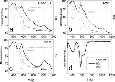 | ||
| Fig. 4 Panels a, b and c: TGA profiles (thin black dashed line), DTG profiles (grey line) and DSC profiles (thick black line) of cobalt hydrotalcites, heated under argon at 10 K min−1. Panel d: DTG profiles under argon. | ||
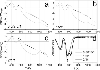 | ||
| Fig. 5 Panels a, b and c: DSC profiles under air (dashed line) and under argon (solid line) of cobalt hydrotalcites, heated under argon at 10 K min−1. Panel d: DTG profiles under air. | ||
| Co/Mg/Al molar ratio | 0.5/2.5/1 | 1/2/1 | 2/1/1 | |
| T range ∼ 303–480 K | T DTG (K) | 400 | 398, 438 | 400, 437 |
| Wt.% | 11 | 11 | 11 | |
| MS | H2O | |||
| T range ∼ 440–700 K | T DTG (K) | 560, 627 | 570, 639 | 558, 626 |
| Wt.% | 21 | 24 | 21 | |
| MS | CO2, NO, H2O | |||
| T range ∼ 700–1173 K | T DTG (K) | — | — | — |
| Wt.% | 7 | 6 | 6 | |
| MS | H2O | |||
| Mass% left at ending T (1173 K) | 61 | 59 | 62 | |
| Theoretical wt.% (Co,Mg,Al)Ox/HT Co | 59 | 61 | 65 | |
Fig. 6 shows the TPR profiles of the calcined samples. The first peak, centered at about 725 K, corresponds to the reduction of Co3+ ions, from the spinel phase, to Co2+ ions. The second peak, ranging from 850 to 900 K, is assigned to the total reduction of Co2+ to Co0.40,41 At 823 K, the highest ESR temperature tested, only sample 0.5/2.5/1_calc has begun to reduce to Co0.
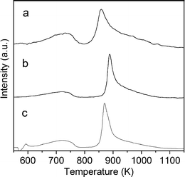 | ||
| Fig. 6 TPR profiles of calcined samples. | ||
Panel d in Fig. 4 and Fig. 5 show the three DTG profiles together, under argon and under air, respectively. They highlight the better thermal stability of sample 1/2/1_as, a fact that could have been expected from the higher crystallinity observed by XRD. Jiang et al.46 and Gennequin et al.47 observed that the addition of cobalt to Mg–Al hydrotalcites destabilizes them thermally, because Co(OH)2 is less stable in air than Mg(OH)2 and Al(OH)3 and Co2+ has less affinity to CO32− than Mg2+. In this sense, the better thermal stability of sample 1/2/1_as could be understood as if not all the cobalt ions would have entered the crystal structure of hydrotalcite, in accordance with XRD data.
The X-ray diffractograms of the three samples after calcination showed a set of common peaks, indexed to MgAl2O4 and/or Co2AlO4 spinels (XRD patterns 01-075-179853 and 00-038-0814,54 respectively; see Fig. 7). Diffractogram of sample 1/2/1_calc illustrates two shoulders at 2θ ≈ 43° and 63° (highlighted with arrows in Fig. 7) which coincide with the main peaks of the rock salt type phase common to MgO and CoO (XRD patterns 01-07-152555 and 01-075-0533,56 respectively). There is also a different relative intensity of the (400) peak at 2θ ≈ 45°: I(1/2/1_calc) = 60% and I(0.5/2.5/1_calc) ≈ I(2/1/1_calc) ≈ 42%. Considering the relative intensity of the peaks in MgAl2O4 and Co2AlO4 patterns,53,54 the former difference in intensity at 45° might indicate a higher amount of magnesium spinel in 1/2/1_calc than cobalt spinel. These results are in accordance with the TGA profile of this sample (higher decomposition temperature) and the XRD data of the as-synthesized samples, suggesting that cobalt ions in sample 1/2/1 are not fully integrated into its crystalline structure.
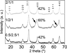 | ||
| Fig. 7 X-Ray diffractograms of calcined samples. | ||
Fig. 8 (above, left) depicts a SEM image of sample 1/2/1_calc, which shows a very homogeneous rounded morphology. By using a backscattered electron detector some particles with higher contrast were observed (white spots in the image above, right), which were assigned to cobalt-rich particles (since magnesium and aluminum have similar electron density, much lower than that of cobalt). Backscattered electron images and the shoulders observed in the X-ray diffractogram suggest that these particles are formed of CoO. A homogeneous area of the calcined sample was analyzed by EDX. The atomic ratio Co:Mg:Al was 27![[thin space (1/6-em)]](https://www.rsc.org/images/entities/char_2009.gif) :
:![[thin space (1/6-em)]](https://www.rsc.org/images/entities/char_2009.gif) 50
50![[thin space (1/6-em)]](https://www.rsc.org/images/entities/char_2009.gif) :
:![[thin space (1/6-em)]](https://www.rsc.org/images/entities/char_2009.gif) 24, close to the nominal value, 25
24, close to the nominal value, 25![[thin space (1/6-em)]](https://www.rsc.org/images/entities/char_2009.gif) :
:![[thin space (1/6-em)]](https://www.rsc.org/images/entities/char_2009.gif) 50
50![[thin space (1/6-em)]](https://www.rsc.org/images/entities/char_2009.gif) :
:![[thin space (1/6-em)]](https://www.rsc.org/images/entities/char_2009.gif) 25. This analysis was contrasted with another performed onto a spot of higher contrast and, as expected, a higher amount of cobalt was detected, Co:Mg:Al = 56
25. This analysis was contrasted with another performed onto a spot of higher contrast and, as expected, a higher amount of cobalt was detected, Co:Mg:Al = 56![[thin space (1/6-em)]](https://www.rsc.org/images/entities/char_2009.gif) :
:![[thin space (1/6-em)]](https://www.rsc.org/images/entities/char_2009.gif) 31
31![[thin space (1/6-em)]](https://www.rsc.org/images/entities/char_2009.gif) :
:![[thin space (1/6-em)]](https://www.rsc.org/images/entities/char_2009.gif) 13. HRTEM confirmed the change of morphology due to calcination in sample 1/2/1_calc (see Fig. 8, below). The sheets of the as-synthesized sample were smashed up into small nanoparticles with average size 6.6 ± 2.2 nm (see below, left image). Some elongated particles were still seen, which were similar to the hydrotalcite structure. Several lattice fringe images of bulk and edge particles were taken (see the two images in Fig. 8, below middle and right). The lattice fringes of the bulk material were indexed to MgAl and/or CoAl spinels,53,54 and the edge particles were indexed mainly to (Co,Mg)O, and also to spinel, in accordance with X-ray diffraction.
13. HRTEM confirmed the change of morphology due to calcination in sample 1/2/1_calc (see Fig. 8, below). The sheets of the as-synthesized sample were smashed up into small nanoparticles with average size 6.6 ± 2.2 nm (see below, left image). Some elongated particles were still seen, which were similar to the hydrotalcite structure. Several lattice fringe images of bulk and edge particles were taken (see the two images in Fig. 8, below middle and right). The lattice fringes of the bulk material were indexed to MgAl and/or CoAl spinels,53,54 and the edge particles were indexed mainly to (Co,Mg)O, and also to spinel, in accordance with X-ray diffraction.
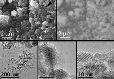 | ||
| Fig. 8 SEM images (SE and backscattered electrons (BSE), above) and TEM images (below) of sample 1/2/1_calc. | ||
Calcination at 823 K not only induced strong morphologic and crystalline changes, but also magnetic ones. The magnetization at room temperature increased linearly with the magnetic field, as a paramagnet (see Fig. 9, above right). At 5 K, the three calcined samples behaved slightly SPM (Fig. 9, above left). At both temperatures, the net magnetization per gram of cobalt decreased as the molar ratio of Co in the formula increased, suggesting an increase in the antiferromagnetic exchange interactions between cobalt atoms, as they get closer to each other. The ZFC-FC curves showed hysteresis below 350, 230 and 300 K for 0.5/2.5/1_calc, 1/2/1_calc and 2/1/1_calc, respectively, although they also showed a remarkable paramagnetic behavior, evidenced by the high increase in magnetization at the lowest temperatures (Fig. 9, below). Samples 1/2/1_calc and 2/1/1_calc presented a maximum in the ZFC curve at 200 and 220 K, respectively, defined as blocking temperature. This feature denotes a change in magnetic behavior with temperature. The blocking temperature of an AFM material is named Néel temperature. The CoAl spinels are AFM materials, with Néel temperatures below 33 K (the Néel temperature of the cobalt spinel, Co3O4).57,58 CoO has a Néel temperature of 289 K. The (Co,Mg)O solid solution bares decreasing values of Néel temperature as the amount of Mg is increased.59,60 In this context, the magnetic phase responsible for the high increase in magnetization at low temperature might be the CoAl spinel (which might have a Néel temperature lower than 5 K, unable to be measured with our equipment) and the magnetic phase responsible for the Néel temperature at 200 and 220 K, for 1/2/1_calc and 2/1/1_calc, might be a (Co,Mg)O solid solution with compositions Co0.7Mg0.3O and Co0.75Mg0.25O, respectively (considering the data published in references59,60). Magnetization measurements are much more sensitive than X-ray diffraction, for what it would be understandable that no peaks of this phase were identified by XRD in samples 0.5/2.5/1 and 2/1/1.
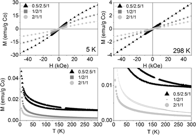 | ||
| Fig. 9 Magnetization curves vs. applied magnetic field at 5 K (above, left) and 298 K (above, right) and vs. temperature at 50 Oe (below: on the left the whole curve and on the right a zoom at low magnetization) of the three calcined samples. | ||
3.3 Ethanol steam reforming
The three catalysts performed well for the steam reforming of ethanol under the conditions tested in this work. Table 2 compiles the ethanol conversion values for each catalytic monolith attained in the 523–823 K temperature range as well as selectivity values on a dry basis at S/C = 2, W/F = 104 g min molEtOH−1 and VHSV = 420 h−1. Data for non-catalytic conditions and chemical equilibrium are added. Total conversion of ethanol was achieved at ca. 823, 773 and 823 K for samples 0.5/2.5/1_calc, 1/2/1_calc and 2/1/1_calc, respectively. At these temperatures, hydrogen selectivity was 67.3%, 69.5% and 67.2%, respectively. Therefore, sample 1/2/1_calc showed the best catalytic performance at the lowest temperature. This better performance might be related to the cobalt cations not being fully integrated into the crystalline structure of the catalyst, as discussed above. Below 773 K, the dehydrogenation of ethanol into acetaldehyde (eqn (5)) was the main reaction. Dimethylketone was also obtained as a by-product, possibly by condensation of acetaldehyde, as reported in other cobalt-based systems.15,16 The temperature of disappearance of acetone matched the temperature of highest hydrogen selectivity for each sample. As expected, the amount of CO increased with temperature at the expense of CO2 according to the water gas shift equilibrium. Interestingly, low amounts of methane were formed, indicating that decomposition of ethanol and methanation reactions were not important.| Co/Mg/Al | T/K | EtOH conv. (%) | Selectivity (%) | ||||||
|---|---|---|---|---|---|---|---|---|---|
| H2 | CO2 | CO | CH4 | C2H4 | CH3 CHO | CH3CO CH3 | |||
| 0.5/2.5/1 | 553 | 2 | 47.1 | 15.6 | 7.8 | 7.8 | — | 21.6 | — |
| 673 | 25 | 53.0 | 16.0 | — | 1.3 | 3.9 | 19.2 | 6.6 | |
| 773 | 94 | 53.2 | 14.7 | 2.5 | 3.5 | 3.9 | 0.2 | 22.1 | |
| 823 | 100 | 67.2 | 10.6 | 16.8 | 4.1 | 0.5 | — | 0.9 | |
| 1/2/1 | 553 | 13 | 38.7 | 22.6 | 6.1 | — | — | 32.7 | — |
| 673 | 66 | 46.4 | 6.7 | 1.1 | 0.5 | 7.1 | 28.2 | 9.9 | |
| 773 | 100 | 69.5 | 10.8 | 16.6 | 1.6 | 0.1 | — | 1.4 | |
| 823 | 100 | 69.0 | 9.1 | 20.0 | 1.9 | — | — | — | |
| 2/1/1 | 553 | 5 | 34.3 | 13.7 | 6.9 | 6.9 | — | 31.2 | 6.9 |
| 673 | 44 | 54.8 | 13.3 | 3.1 | 2.0 | 5.7 | 13.1 | 8.0 | |
| 773 | 88 | 56.9 | 15.7 | 4.2 | 5.1 | 2.9 | — | 15.1 | |
| 823 | 100 | 67.4 | 9.2 | 20.5 | 2.9 | — | — | — | |
| No catalyst | 823 | 0.7 | 8.5 | 1.9 | — | 1.3 | 1.5 | 0.5 | 8.3 |
| 1050 | 100 | 33 | 1.0 | 27 | 25 | 10 | 4.3 | — | |
| Chemical equilibrium | 823 | — | 59.7 | 20.3 | 6.3 | 13.7 | — | — | — |
Fig. 10 shows the stability of the catalytic monoliths tested in terms of hydrogen yield (defined as ethanol conversion multiplied by hydrogen molar fraction on a dry basis) over time on stream at 823 K under a pure ethanol–water mixture (S/C = 2, W/F = 390 g min molEtOH−1, VHSV = 660 h−1). Samples showed a slow deactivation over time, but to a different degree; the stability follows the trend 1/2/1_calc > 2/1/1_calc ∼ 0.5/2.5/1_calc. Therefore, the catalytic honeycomb 1/2/1_calc exhibited the best catalytic behavior, both in terms of yield towards hydrogen and stability. This result merits to be highlighted because to the best of our knowledge this is the first cobalt-based catalyst which shows such stability for ESR under undiluted ethanol-water mixtures. In most cobalt-based systems strong deactivation occurs readily under high ethanol loads due to extensive carbon deposition.
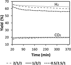 | ||
| Fig. 10 Hydrogen yield obtained under ESR at 823 K. S/C = 2, W/F = 390 g min molEtOH−1, VHSV = 660 h−1. Grey dash line: 2/1/1, full grey line: 1/2/1, black dash line: 0.5/2.5/1. | ||
3.4 Samples after ESR
The reacted samples showed simple XRD profiles (Fig. 11) with three peaks, which correspond to the rock salt type phase, common to MgO and CoO (XRD patterns 01-07-152555 and 01-075-053356). Samples 0.5/2.5/1_reac and 2/1/1_reac showed shoulders at 36°, 44°, 56° and 60° 2θ, which correspond to the spinel phase. The transformation from spinel to CoO was not complete in these samples, in contrast to sample 1/2/1_reac. The crystalline size, calculated using Scherrer's formula, is nanometric in all samples (between 5 and 12 nm). On the other hand, bands at 565 and 680 cm−1 in the IR spectra are prominent, which are assigned to Coδ+–O.61 The morphology of sample 1/2/1_reac observed by SEM (Fig. 12) was similar to sample 1/2/1_calc, that is, a cluster-of-grape morphology of small, rounded particles together with cobalt-rich particles. Furthermore, only a few sporadic carbon nanotubes could be observed. The Co:Mg:Al elemental ratio analyzed by EDS in homogeneous areas was also close to the nominal value (22/52/26).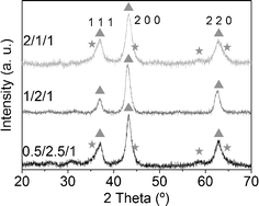 | ||
| Fig. 11 X-Ray diffractograms of reacted samples. Triangles indicate CoMgO solid solution and stars spinel phase. | ||
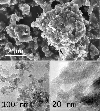 | ||
| Fig. 12 Representative SEM (above) and TEM (below) images of sample 1/2/1_reac. | ||
Besides, TEM images showed that sample 1/2/1_reac was composed of rounded and kidney-like particles, with an average size of 7.4 ± 1.9 nm (Fig. 12). Some elongated structures were visible, which were understood as rehydrated hydrotalcites. Again, no significant carbon deposition was observed and only a few carbon nanotubes could be detected. From lattice-fringe images and Fourier transform (FT) analysis, a clear difference in composition between the bulk matrix and the cobalt-rich particles was encountered. The former is composed only by (Co,Mg)O solid solution, whereas the cobalt-rich particles showed interplanar distances corresponding to spinel phases, similar to the ones identified in the calcined sample. Interestingly, no metallic cobalt particles were found, which have been extensively reported to occur in cobalt catalysts after ethanol steam reforming operation.12,13,15,16,33
The reacted samples showed a new magnetic behavior. At room temperature the magnetization vs. field curves revealed two magnetic roles (Fig. 13): a ferromagnetic one (FM), illustrated by the hysteresis cycle at low fields, and another paramagnetic (PM), illustrated by the linear increase at high fields. At 5 K the hysteresis is still visible for samples 0.5/2.5/1_reac and 1/2/1_reac, but no more for 2/1/1_reac. The ferromagnetic behavior must be attributed to the presence of metallic cobalt. Nevertheless, the percentage of metallic cobalt in the samples is very low, considering that its bulk saturation magnetization is 163 emu g−1 and the saturation magnetization of samples 0.5/2.5/1_reac, 1/2/1_reac and 2/1/1_reac is only 9.65, 1.18 and 0.17 emu/g Co, respectively. Therefore, we estimate 5.9wt.%, 0.7wt.% and 0.1wt.%, of metallic cobalt in each sample. The ZFC-FC curves show a big hysteresis for sample 0.5/2.5/1_reac, smaller hysteresis for 1/2/1_reac and even smaller for 2/1/1_reac, in accordance with the previous data. The Néel temperatures in the three cases are over, but close to, 300 K. Based on the above, the reacted samples contain two magnetic phases: traces of metallic cobalt (FM) and a main AFM phase, which is attributed to oxidized cobalt (CoO or (CoMg)O solid solution and, likely, a small contribution of CoAl spinel, according to XRD and HRTEM). Another datum to support that the oxidized cobalt is the main phase is the fact that the higher the amount of cobalt, the smaller the net magnetization of the reacted samples, in accordance with the behavior of antiferromagnetic materials. No nanoparticles of metallic cobalt were identified by HRTEM, although its high electronic density favors its detection due to a higher electron contrast compared to magnesium-and aluminum-containing oxides. Together with the small saturation magnetization values, we conclude that there are very few nanoparticles and they have very small size.
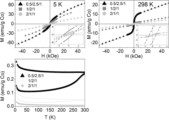 | ||
| Fig. 13 Above: Magnetization curves of reacted samples vs. applied magnetic field at 5 K and 298 K (insets: magnification of low field areas). Below: Magnetization curves of reacted samples vs. temperature at 50 Oe. | ||
The reacted samples were also analyzed by TPR coupled to mass spectroscopy. It was observed that some methane was evolved, between 673 and 1073 K, due to the reduction of superficial carbon. After calibration of the signal m/z = 15 (CH3+), the amount of methane, and therefore of carbon, was quantified for the three samples. The mass of carbon for samples 0.5/2.5/1_reac, 1/2/1_reac and 2/1/1_reac was 4.4, 0.8 and 0.1 wt.% C, respectively. Considering that the samples were submitted to ethanol reforming conditions for 7 h, they generated 6.3 × 10⁻³, 1.1 × 10⁻³ and 1.4 × 10⁻⁴ g C g catalyst−1 h−1. The amount of carbon is, in any case, scarce for cobalt catalysts working under high ethanol load. Sample 0.5/2.5/1 is catalytically the less stable, matching its highest amount of deposited carbon.
The powders of the reacted samples were pressed into pellets and analyzed by XPS (see Fig. 14). Differences in their surface composition were found. Surprisingly, the Co/Mg/Al molar ratios at the surface were 1.1/1.3/1, 0.9/2.0/1 and 0.9/1.2/1, for samples 0.5/2.5/1_reac, 1/2/1_reac and 2/1/1_reac, respectively. Sample 0.5/2.5/1 had 4 times more cobalt at the surface than the nominal value, sample 1/2/1 was similar to bulk value and sample 2/1/1 had around 37% of the nominal cobalt at the surface. Each Co2p spectra is composed of two main peaks (components 2p3/2 and 2p1/2) and two satellites. In sample 0.5/2.5/1_reac each main peak can be fitted to two components: the first one, at 779.6 eV, can be assigned to metallic cobalt (according to its separation between components 2p3/2 and 2p1/2 of 15.05 eV) and the second one, at 781.1 eV, corresponds to oxidized cobalt (its separation between components 2p3/2 and 2p1/2 is 15.50 eV and is accompanied by a satellite at 787.3 eV). The atomic percentage of metallic cobalt in the surface is 8.2%. In contrast, samples 1/2/1_reac and 2/1/1_reac showed only one component of oxidized cobalt at 781.4 eV (2p3/2) and 797.2 eV (2p1/2). Only sample 0.5/2.5/1_reac bears metallic cobalt, in accordance with its highest carbon deposition. Considering the results of magnetometry and XPS, there is a relationship between the cobalt/magnesium molar ratio at the surface and the amount of metallic cobalt: the higher amount of cobalt at the surface, the higher the amount of metallic cobalt in the sample.
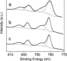 | ||
| Fig. 14 Co 2p XPS spectra of sample 0.5/2.5/1_reac (a), 1/2/1_reac (b) and 2/1/1_reac (c). | ||
Finally, we decided to carry out an in situ XPS study over the sample 1/2/1 in order to get insight into the occurrence of surface reduced cobalt under reaction conditions, which has been largely considered the active species for ESR over cobalt systems.13,33,35,36 Sample 1/2/1 was analyzed in situ in its as-synthesized form, after calcination at 823 K, after ESR reaction at 823 K (the evolution of reaction products was followed simultaneously by mass spectrometry) and also after being reduced at 823 K under a hydrogen flow. All the analyses were performed consecutively, under high vacuum.
The spectra corresponding to the Co 2p core level are shown in Fig. 15. The spectrum of the as-prepared sample (Fig. 15a) showed two peaks centered at binding energies of 781.0 (Co 2p3/2) and 797.2 eV (Co 2p1/2), along with two satellites. The position of these peaks and their separation are ascribed to Co2+ species. The high intensities of the satellites are in accordance with the structure of the cobalt hydrotalcite, where the metal occupies octahedral sites in a 2+ oxidation state. After calcination (Fig. 15b) the intensity of the satellite lines decreased relative to the spin-orbital splitting components. In addition, two sets of signals appeared at 781.0/796.0 eV and 781.4/797.5 eV, which correspond to Co2+ species in different environments. The satellite lines were located at about 8–9 eV above the photo lines, thus indicating a partial charge transfer from Co2+, probably due to a strong interaction with Mg and Al.62 The presence of these two Co2+ species could be related to the formation of cobalt aluminate spinel and (Co,Mg)O solid solution,63,64 in accordance with XRD and magnetic measurements. Co2+ in (Co,Mg)O solid solution exhibits an octahedral environment whereas Co2+ in cobalt spinel may occupy both octahedral and tetrahedral positions, depending on Al3+ substitution. After ESR (Fig. 15c) the XP spectrum showed again strong satellite lines, which were located at about 6–6.5 eV above the photo lines. Contrary to that, very weak satellites, to be shifted about 10–11 eV to higher binding energies from the main peaks, are characteristic of Co3+ species, and metallic cobalt does not contain shake-up satellite structure at all.65 Moreover, the full width at half maximum (FWHM) of Co0 is characteristically narrow (< 1.5 eV) and FWHM values of the bands in Fig. 14c are about 2.5–3 eV. Therefore, the only species identified at the surface of the catalyst with in situ XPS under ethanol steam reforming conditions is Co2+. Contrarily to other in situ XPS experiments conducted under similar conditions,13 no reduced cobalt species has been identified. In the spectrum, two Co2+ species are present at 780.7/796.7 eV and 782.7/796.6 eV, which may correspond to the cobalt-alumina spinel and CoO phases infused from magnetic measurements as well. Finally, the sample was exposed to hydrogen flow at the same temperature used for ESR (823 K). The resulting spectrum (Fig. 15d) is virtually identical to that recorded after ESR, thus indicating that at this temperature Co2+ species are stable and do not evolve into metallic entities or, if present (0.7% inferred from magnetic measurements), they escape XPS detection. Actually, the TPR profile of sample 1/2/1_calc confirms that Co2+ reduces significantly only over 860 K (Fig. 6), and at reforming temperature, 823 K, it remains oxidized. This in situ experiment allows us to conclude that Co2+ species should be active for the ethanol steam reforming reaction. Moreover, the absence or trace amount of metallic cobalt at the surface of the catalyst would preclude carbon deposition. Together, this represents a new generation of cobalt catalysts for producing hydrogen from ethanol at moderate temperature.
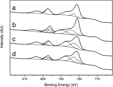 | ||
| Fig. 15 Co 2p in situ XP spectra of sample 1/2/1 as-synthesized (a), calcined (b), reacted (c) and reduced (d). | ||
4. Conclusions
We have synthesized a cobalt-based catalyst for ESR derived from Co/Mg/Al hydrotalcite that presents high activity and selectivity towards hydrogen at moderate temperature and remarkable stability under high ethanol load. A thorough characterization has evidenced that it contains CoAl spinel particles as well as CoO strongly interacting with MgO. Unlike previously reported cobalt catalysts for ESR, metallic cobalt has been only detected by magnetic measurements in very small amounts. Consequently, our material scarcely generates carbon under practical ESR conditions. In situ experiments suggest that Co2+ species are active for ESR reaction. This is a meaningful result, since the catalytic activity in reforming reactions over cobalt-based systems has been traditionally assigned only to metallic cobalt.Acknowledgements
This work has been funded by MICINN project CTQ2009-12520. R.E. is grateful to CONACYT México for a PhD grant and E.T. to UPC for a postdoc grant. F.M. and J.L. are grateful to ICREA Academia program.References
- A. Haryanto, S. Fernando, N. Murali and S. Adhikari, Energy & Fuels, 2005, 19, 2098–2106 CrossRef CAS.
- P. D. Vaidya and A. E. Rodrigues, Chemical Engineering Journal, 2006, 117, 39–49 CrossRef CAS.
- M. Ni, D. Y. C. Leung and M. K. H. Leung, International Journal of Hydrogen Energy, 2007, 32, 3238–3247 CrossRef CAS.
- G. Kolb, ed. Wiley-VCH, 2008, pp. 1–434.
- J. Llorca, in Handbook of sustainable energy, ed. W. H. Lee and V. G. Cho, Nova Publishers, 2010, pp. 693–699 Search PubMed.
- A. Casanovas, M. Saint-Gerons, F. Griffon and J. Llorca, International Journal of Hydrogen Energy, 2008, 33, 1827–1833 CrossRef CAS.
- G. A. Deluga, J. R. Salge, L. D. Schmidt and X. E. Verykios, Science, 2004, 303, 993–997 CrossRef CAS.
- F. Frusteri and S. Freni, Journal of Power Sources, 2007, 173, 200–209 CrossRef CAS.
- H. Idriss, M. Scott, J. Llorca, S. C. Chan, W. Chiu, P. Y. Sheng, A. Yee, M. A. Blackford, S. J. Pas, A. J. Hill, F. M. Alamgir, R. Rettew, C. Petersburg, S. D. Senanayake and M. A. Barteau, Chemsuschem, 2008, 1, 905–910 CrossRef CAS.
- J. Llorca, A. Casanovas, T. Trifonov, A. Rodriguez and R. Alcubilla, Journal of Catalysis, 2008, 255, 228–233 CrossRef CAS.
- A. Casanovas, C. de Leitenburg, A. Trovarelli and J. Llorca, Catalysis Today, 2008, 138, 187–192 CrossRef CAS.
- M. Dominguez, E. Taboada, E. Molins and J. Llorca, Catalysis Today, 2008, 138, 193–197 CrossRef CAS.
- M. Dominguez, E. Taboada, H. Idriss, E. Molins and J. Llorca, Journal of Materials Chemistry, 2010, 20, 4875–4883 RSC.
- A. Casanovas, M. Dominguez, C. Ledesma, E. Lopez and J. Llorca, Catalysis Today, 2009, 143, 32–37 CrossRef CAS.
- J. Llorca, N. Homs, J. Sales and P. R. de la Piscina, Journal of Catalysis, 2002, 209, 306–317 CrossRef CAS.
- J. Llorca, P. R. de la Piscina, J. A. Dalmon, J. Sales and N. Homs, Applied Catalysis B-Environmental, 2003, 43, 355–369 CrossRef CAS.
- J. Llorca, N. Homs, J. Sales, J. L. G. Fierro and P. R. de la Piscina, Journal of Catalysis, 2004, 222, 470–480 CrossRef CAS.
- S. Tuti and F. Pepe, Catalysis Letters, 2008, 122, 196–203 CrossRef CAS.
- A. E. Galetti, M. F. Gomez, L. A. Arrua, A. J. Marchi and M. C. Abello, Catalysis Communications, 2008, 9, 1201–1208 CrossRef CAS.
- J. C. Vargas, S. Libs, A. C. Roger and A. Kiennemann, Catalysis Today, 2005, 107-08, 417–425 CrossRef.
- P. Bichon, G. Haugom, H. J. Venvik, A. Holmen and E. A. Blekkan, Topics in Catalysis, 2008, 49, 38–45 CrossRef CAS.
- S. S. Y. Lin, D. H. Kim and S. Y. Ha, Catalysis Letters, 2008, 122, 295–301 CrossRef CAS.
- S. Freni, S. Cavallaro, N. Mondello, L. Spadaro and F. Frusteri, Catalysis Communications, 2003, 4, 259–268 CrossRef CAS.
- J. Sun, X. P. Qiu, F. Wu and W. T. Zhu, International Journal of Hydrogen Energy, 2005, 30, 437–445 CrossRef CAS.
- F. Marino, G. Baronetti, M. Jobbagy and M. Laborde, Applied Catalysis a-General, 2003, 238, 41–54 CrossRef CAS.
- M. S. Batista, R. K. S. Santos, E. M. Assaf, J. M. Assaf and E. A. Ticianelli, Journal of Power Sources, 2004, 134, 27–32 CrossRef CAS.
- H. Song and U. S. Ozkan, Journal of Catalysis, 2009, 261, 66–74 CrossRef CAS.
- H. Song, L. Z. Zhang, R. B. Watson, D. Braden and U. S. Ozkan, Catalysis Today, 2007, 129, 346–354 CrossRef CAS.
- H. Wang, J. L. Ye, Y. Liu, Y. D. Li and Y. N. Qin, Catalysis Today, 2007, 129, 305–312 CrossRef CAS.
- M. Benito, R. Padilla, L. Rodriguez, J. L. Sanz and L. Daza, Journal of Power Sources, 2007, 169, 167–176 CrossRef CAS.
- A. Kaddouri and C. Mazzocchia, Catalysis Communications, 2004, 5, 339–345 CrossRef CAS.
- A. Chica and S. Sayas, Catalysis Today, 2009, 146, 37–43 CrossRef CAS.
- J. Llorca, P. R. de la Piscina, J. A. Dalmon and N. Homs, Chemistry of Materials, 2004, 16, 3573–3578 CrossRef CAS.
- V. M. Garcia, E. Lopez, M. Serra and J. Llorca, Journal of Power Sources, 2009, 192, 208–215 CrossRef CAS.
- J. Llorca, N. Homs and P. R. de la Piscina, Journal of Catalysis, 2004, 227, 556–560 CrossRef CAS.
- J. Llorca, J. A. Dalmon, P. R. de la Piscina and N. Homs, Appl. Catal., A, 2003, 243, 261–269 CrossRef CAS.
- G. Busca, U. Costantino, T. Montanari, G. Ramis, C. Resini and M. Sisani, Int. J. Hydrogen Energy, 2010, 35, 5356–5366 CrossRef CAS.
- L. He, H. Berntsen, E. Ochoa-Fernandez, J. C. Walmsley, E. A. Blekkan and D. Chen, Top. Catal., 2009, 52, 206–217 CrossRef CAS.
- A. F. Lucredio, J. A. Bellido and E. M. Assaf, Catal. Commun., 2011, 12, 1286–1290 CrossRef CAS.
- A. Casanovas, C. de Leitenburg, A. Trovarelli and J. Llorca, Chem. Eng. J., 2009, 154, 267–273 CrossRef CAS.
- A. Casanovas, M. Roig, C. de Leitenburg, A. Trovarelli and J. Llorca, Int. J. Hydrogen Energy, 2010, 35, 7690–7698 CrossRef CAS.
- M. Ohyama, H. Kozuka and T. Yoko, Thin Solid Films, 1997, 306, 78–85 CrossRef CAS.
- Y. Men, H. Gnaser, R. Zapf, V. Hessel, C. Ziegler and G. Kolb, Appl. Catal., A, 2004, 277, 83–90 CrossRef CAS.
- G. J. Ross and H. Kodama, American Mineralogist., 1967, 52, 1036 CAS.
- T. Baird, K. C. Campbell, P. J. Holliman, R. Hoyle, D. Stirling and B. P. Williams, J. Chem. Soc., Faraday Trans., 1995, 91, 3219–3230 RSC.
- Z. Jiang, J. J. Yu, J. Cheng, T. C. Mao, M. O. Jones, Z. P. Hao and P. P. Edwards, Fuel Process. Technol., 2010, 91, 97–102 CrossRef CAS.
- C. Gennequin, S. Siffert, R. Cousin and A. Aboukais, Top. Catal., 2009, 52, 482–491 CrossRef CAS.
- K. Yan, X. M. Xie, J. P. Li, X. L. Wang and Z. Z. Wang, J. Nat. Gas Chem., 2007, 16, 371–376 CrossRef CAS.
- J. Perez-Ramirez, A. Ribera, F. Kapteijn, E. Coronado and C. J. Gomez-Garcia, J. Mater. Chem., 2002, 12, 2370–2375 RSC.
- A. A. Khassin, V. F. Anufrienko, V. N. Ikorskii, L. M. Plyasova, G. N. Kustova, T. V. Larina, I. Y. Molina and V. N. Parmon, Phys. Chem. Chem. Phys., 2002, 4, 4236–4243 RSC.
- D. Tichit, M. H. Lhouty, A. Guida, B. H. Chiche, F. Figueras, A. Auroux, D. Bartalini and E. Garrone, J. Catal., 1995, 151, 50–59 CrossRef CAS.
- L. Chmielarz, P. Kustrowski, A. Rafalska-Lasocha, D. Majda and R. Dziembaj, Appl. Catal., B, 2002, 35, 195–210 CrossRef CAS.
- T. Yamanaka and Y. Takeuchi, Z. Kristallogr., 1983, 165, 65–78 CrossRef CAS.
- P. G. Casado and I. Rasines, J. Solid State Chem., 1984, 52, 187–193 CrossRef.
- E. Schiebold, Z. Kristallogr., Kristallgeom., Kristallphys., Kristallchem., 1921, 56, 430 CAS.
- W. D. Johnston, R. R. Heikes and D. Sestrich, J. Phys. Chem. Solids, 1958, 7, 1–13 CrossRef CAS.
- O. H. Hansteen, H. Fjellvag and B. C. Hauback, Acta Chem. Scand., 1998, 52, 1285–1292 CrossRef CAS.
- T. Suzuki, H. Nagai, M. Nohara and H. Takagi, Journal of Physics-Condensed Matter, 2007, 19 CAS.
- N. Mironova-Ullmane, U. Ullmanis, A. Kuzmin, I. Sildos, M. Pärs, M. Cestelli Guidi, M. Piccinini and A. Marcelli, Phys. Solid State, 2008, 50, 1723–1726 CrossRef.
- A. Z. Menshikov, Y. A. Dorofeev, N. A. Mironova and M. V. Medvedev, Solid State Commun., 1996, 98, 839–842 CrossRef CAS.
- T. Montanari, M. Sisani, M. Nocchetti, R. Vivani, M. C. H. Delgado, G. Ramis, G. Busca and U. Costantino, Catal. Today, 2010, 152, 104–109 CrossRef CAS.
- R. Guil-Lopez, R. M. Navarro, M. A. Pena and J. L. G. Fierro, Int. J. Hydrogen Energy, 2011, 36, 1512–1523 CrossRef CAS.
- S. Kannan and C. S. Swamy, Catal. Today, 1999, 53, 725–737 CrossRef CAS.
- K. Omata, T. Takada, S. Kasahara and M. Yamada, Appl. Catal., A, 1996, 146, 255–267 CrossRef CAS.
- A. A. Khassin, T. M. Yurieva, V. V. Kaichev, V. I. Bukhtiyarov, A. A. Budneva, E. A. Paukshtis and V. N. Parmon, J. Mol. Catal. A: Chem., 2001, 175, 189–204 CrossRef CAS.
| This journal is © The Royal Society of Chemistry 2012 |
