One-step preparation of ZnO nanoparticle-decorated reduced graphene oxide composites and their application to photocurrent generation†
Jingqi
Tian
ab,
Sen
Liu
a,
Haiyan
Li
a,
Lei
Wang
a,
Yingwei
Zhang
a,
Yonglan
Luo
a,
Abdullah M.
Asiri
cd,
Abdulrahman O.
Al-Youbi
cd and
Xuping
Sun
*acd
aState Key Lab of Electroanalytical Chemistry, Changchun Institute of Applied Chemistry, Chinese Academy of Sciences, Changchun, 130022, Jilin, China
bGraduate School of the Chinese Academy of Sciences, Beijing, 100039, China
cChemistry Department, Faculty of Science, King Abdulaziz University, Jeddah, 21589, Saudi, Arabia
dCenter of Excellence for Advanced Materials Research, King Abdulaziz University, Jeddah, 21589, Saudi, Arabia. E-mail: sunxp@ciac.jl.cn.; Fax: (+86)-431-85262065
First published on 5th January 2012
Abstract
In this communication, we develop a facile, one-step strategy towards the rapid synthesis of ZnO nanoparticle-decorated reduced graphene oxide (rGO–ZnO) composites by directly immersing Zn plate in a GO solution containing ammonia with the aid of ultrasonication at room temperature. The rGO–ZnO composites obtained have applications in photocurrent generation in the visible spectral region of white light using zinc porphyrin (ZnP) as a photosensitizer.
Graphene, a flat monolayer of sp2-bonded carbon atoms tightly packed into a two-dimensional (2D) honeycomb lattice, has attracted intense scientific interest due to its high surface area (∼2600 m2 g−1), high chemical stability, and unique electronic and mechanical properties.1 Among the various exciting characteristics, the superior electrical conductivity and mechanical properties make graphene an excellent electron-transport material in the process of photocatalysis.2 It is expected that the hybridization of semiconductors with graphene would reduce the recombination of charge carriers, and increase the separation efficiency. Thus, considerable research efforts have been put into preparing graphene decorated with metal nanoparticles or metal oxides to increase the efficiency of photocatalysis3 and solar cells.4
As an important wide-band gap (3.2 eV) and large exaction binding energy (60 meV) semiconductor, ZnO has also drawn intense attention such as a good electron acceptor and conducting layer.5 The hybrid of graphene and ZnO can act in a cooperative way by increasing the migration efficiency of photoinduced electrons and effectively reducing recombination.6 Consequently, various methods have been developed to synthesize graphene–ZnO composites such as plasma-enhanced chemical vapor deposition (PECVD), metal–organic chemical vapor deposition (MOCVD) and solvothermal synthesis.7 Unfortunately, all mentioned methods suffer from drawbacks such as high temperature, special equipment or complicated conditions, which limit their wide applications. More recently, Kamat and co-workers have constructed an efficient hierarchical electron transfer (ET) cascade system on a semiconducting electrode using reduced GO (rGO) as a 2D sheet to anchor organic/inorganic hybrid materials of Zinc porphyrin (ZnP)/ZnO nanoparticles (ZnONP) for photocurrent generation in the visible region of light.8 However, several steps are needed to fabricate rGO–ZnO composites in their experiments which is time-consuming. Herein, we develop a facile strategy towards rapid preparation of rGO–ZnO composites. The formation of the composites occurs in a single step, carried out by directly immersing Zn plate in a GO ammonia solution with the aid of a short period of ultrasonication at room temperature. We further successfully demonstrate the application of such composites in photocurrent generation in the visible spectral region of white light with the use of zinc porphyrin (ZnP) as a photosensitizer.
The mechanism for the chemical reduction of GO with Zn plate was similar to that of the zinc-manganese primary batteries9 and also has been discussed by Liu et al.10 In the Zn–GO primary battery, Zn, GO and ammonia served as the anode, cathode and electrolyte, respectively. The electrons of the Zn are discharged to form H˙ and a zinc ammonia complex ion, which can promote the continued dissolution of the Zn plate and convert GO to rGO at the same time. Scheme 1 shows a schematic diagram to illustrate the preparation process.
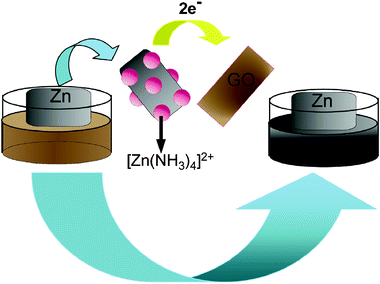 | ||
| Scheme 1 A scheme (not to scale) illustrating the rGO–ZnO preparation. | ||
Fig. 1 shows the UV-vis spectra of an aqueous dispersion of GO and the resulting rGO–ZnO composites. As excepted, GO exhibits strong bands centered at 230 and 300 nm, corresponding to π–π* transitions of the aromatic C![[double bond, length as m-dash]](https://www.rsc.org/images/entities/char_e001.gif) C band and n–π* transitions of the C
C band and n–π* transitions of the C![[double bond, length as m-dash]](https://www.rsc.org/images/entities/char_e001.gif) O band in GO, respectively. It is clearly seen that the absorption peak gradually red-shifts from 230 nm to 262 nm, indicating the formation of rGO.1f Moreover, the absorption peak of ZnONPs usually appears in the range of 280 to 400 nm, which could be covered up by the strong peak of rGO around 300 nm in our experiment. Fig. 1 inset shows photographs of aqueous dispersion of GO (left) and the resulting rGO–ZnO composites (right), revealing a distinct color change from pale-yellow to black after reaction. Such an observation provides another piece of evidence to support the formation of rGO.
O band in GO, respectively. It is clearly seen that the absorption peak gradually red-shifts from 230 nm to 262 nm, indicating the formation of rGO.1f Moreover, the absorption peak of ZnONPs usually appears in the range of 280 to 400 nm, which could be covered up by the strong peak of rGO around 300 nm in our experiment. Fig. 1 inset shows photographs of aqueous dispersion of GO (left) and the resulting rGO–ZnO composites (right), revealing a distinct color change from pale-yellow to black after reaction. Such an observation provides another piece of evidence to support the formation of rGO.
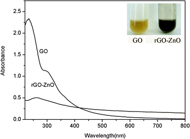 | ||
| Fig. 1 UV-vis spectra of aqueous dispersion of GO and the resulting rGO–ZnO composites. Inset: photographs of dispersion of GO (left) and rGO–ZnO (right). | ||
Fig. 2A shows a typical TEM image of GO sheets thus prepared, showing they are several micrometres in size. After the reaction with Zn plate in the presence of ammonia, a large amount of nanoparticles, several nanometres in diameter were found to decorate the surface of the sheet, as shown in Fig. 2B. To gain further insight into the nanoparticles, a HRTEM image taken from a typical area of the nanosheet shown in Fig. 2B was exhibited in Fig. 2C. It can be seen that there are many dots decorating the surface of sheet and the lattice fringes of an interplane distance was measured to be 0.28 nm, which corresponds to the (100) plane of the ZnO crystals.11 It is of importance to note that even after a period of 20 min of sonication during the preparation of the sample, the ZnO nanoparticles are still strongly anchored on the surface of rGO sheets with a high density, suggesting a strong interaction between ZnONPs and rGO sheets. This intimate contact makes the electronic interaction between ZnO nanoparticles and rGO possible, improving the charge separation. Additionally, the existence of Zn in the nanocomposites has been proved by the peaks of Zn in EDS data (Fig. 2D). The appearance of the Cu and C element can be assigned to the carbon-coated copper grid used for TEM and EDS measurements.
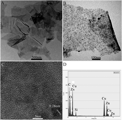 | ||
| Fig. 2 TEM images of (A) GO, (B) rGO–ZnO, (C) HRTEM image and (D) the corresponding energy-dispersed spectrum of rGO–ZnO composites. | ||
Fig. S1A and S1B, ESI† show the Raman spectra of GO and the as formed rGO–ZnO composites, respectively. It is established that graphene obtained by chemical reduction of GO exhibits two characteristic main peaks: the D band at ∼1350 cm−1, arising from a breathing mode of κ-point photons of A1g symmetry; the G band at 1575 cm−1, arising from the first order scattering of the E2g phonon of sp2 C atoms.12 In our present study, it is seen that GO exhibits a D band at 1350 cm−1 and a G band at 1596 cm−1, while the corresponding bands of rGO–ZnO are 1335 and 1576 cm−1, respectively. The G band of rGO–ZnO red-shifts from 1596 to 1576 cm−1, which is attributed to the high ability for recovery of the hexagonal network of carbon atom.13 The red-shift of D band shown in Fig. S2B, ESI† could be attributed to the chemical interaction between ZnO nanoparticles and rGO.14 It is also found that rGO–ZnO composites show relatively higher intensities of the D to G band than that for GO. These observations further confirm the formation of new graphitic domains after the reaction.15
We further explored the application of the composites for photocurrent generation in the visible range of light using ZnP as a photosensitizer. To do this, we fabricated rGO–ZnO–ZnP composites by the self-assembly of rGO–ZnO and ZnP first. Fig. 3 shows the SEM images of the composites thus formed. It clearly suggests the sample comprises of multiple sheets of rGO and the composites have a roughened surface, confirming the formation of rGO–ZnO–ZnP by self-assembly. Given that there are numerous –OH groups on the surface of ZnO, it is expected that ZnO can react with –COOH groups of ZnP molecules and are wrapped by them. Additionally, the aromatically structured ZnP molecules can also have close interactions with the undecorated space of the rGO sheets via π–π stacking.16 Both these two interactions contribute to the formation of rGO–ZnO–ZnP composites. Fig. S2, † shows the absorption spectra of rGO–ZnO modified ITO and rGO–ZnO–ZnP modified ITO. It is seen that an intense peak appears around 410 nm for the rGO–ZnO–ZnP modified ITO, indicating the presence of ZnP in the nanocomposites. This result provides another piece of evidence for the successful assembly of ZnP on rGO–ZnO composites.
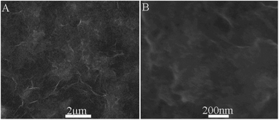 | ||
| Fig. 3 (A) Low and (B) high magnification SEM images of rGO–ZnO–ZnP composites. | ||
The photocurrent responses of rGO–ZnO, ZnP, ZnO–ZnP, and rGO–ZnO–ZnP modified ITO electrodes under white light illumination are shown in Fig. 4. The rGO–ZnO modified electrode shows a negligible photoelectrochemical effect under illumination. Due to the ability of ZnP molecules to absorb visible light, the ZnP modified electrode exhibits a prompt photocurrent response. The ZnO–ZnP modified ITO presents an enhancement in the photocurrent compared with the ZnP modified electrode, which can be attributed to the effective separation of electron-hole pairs on the interface of ZnO and ZnP. Note that the presence of rGO leads to further significant enhancement of the photocurrents of the ZnO–ZnP modified electrode, indicating that rGO has a positive role on photocurrent generation for the modified electrode. On one hand, rGO can accept electrons from ZnO–ZnP composites; on the other hand, rGO can facilitate electron transfer within the composite film.8
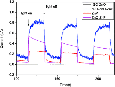 | ||
| Fig. 4 Photocurrent responses of rGO–ZnO, ZnP, ZnO–ZnP, and rGO–ZnO–ZnP modified ITO electrodes in a standard three-compartment cell along with a Pt wire counter electrode and a reference electrode (Ag/AgCl) under white light illumination (λ > 400 nm; input power: 100 mW cm−2; electrolyte: 1 M Na2SO4 aqueous solution; electrode potential of 0 V vs.Ag/AgCl). | ||
On the basis of the film structures and the photoelectrochemical properties of the rGO–ZnO–ZnP composites and the previously established photocurrent generation mechanism involved in porphyrin-semiconducting oxide composites,17 the possible photocurrent generation mechanism in our present study can be proposed as follows. Under the visible-light illumination (λ > 400 nm), first, ZnP is excited to form ZnP* (−0.99 V vs.NHE) which dissociates to an electron and a hole at the ZnP–ZnO interface. The photogenerated electrons inject into the conduction band (CB) of ZnONPs (−0.5 V vs.NHE). At the same time, the photogenerated electrons can also inject to rGO (∼0 V vs.NHE) and the ITO electrode. The collected electrons in the CB of ZnONPs are transferred into the ITO electrode through the rGO network in the rGO–ZnO–ZnP composites, together with direct electron injection from ZnONPs to the electrode. Then, the oxidized porphyrin undergoes electron transfer reduction with OH− in the electrolyte solution, resulting in photocurrent generation. Scheme 2 shows a schematic illustration for the energy diagram.
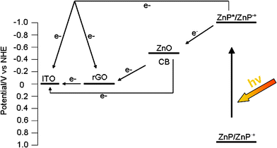 | ||
| Scheme 2 Schematic illustration for the energy diagram. | ||
In summary, by direct immersing a Zn plate in a GO solution containing ammonia with the aid of ultrasonication at room temperature, we have prepared rGO–ZnO composites. The application of such rGO–ZnO composites in photocurrent generation has also been demonstrated successfully. Our present study is important because it provides a facile approach for one-step rapid synthesis of rGO–ZnO composites for applications.
Acknowledgements
This work was supported by the National Natural Science Foundation of China (No. 21175129) and the National Basic Research Program of China (No. 2011CB935800).References
- (a) K. S. Novoselov, S. V. Geim, S. V. Morozov, D. Jiang, Y. Zhang, S. V. Dubonos, I. V. Grigorieva and A. A. Firsov, Science, 2004, 306, 666 CrossRef CAS; (b) M. J. Allen, V. C. Tung and R. B. Kaner, Chem. Rev., 2010, 110, 132 CrossRef CAS; (c) X. Huang, Z. Yin, S. Wu, X. Qi, Q. He, Q. Zhang, Q. Yan, F. Boey and H. Zhang, Small, 2011, 7, 1876 CrossRef CAS; (d) X. Huang, X. Qi, F. Boey and H. Zhang, Chem. Soc. Rev., 2012 10.1039/C1CS15078B; (e) D. Li, M. B. Muller, S. Gilje, R. B. Kaner and G. G. Wallace, Nat. Nanotechnol., 2008, 3, 101 CrossRef CAS; (f) S. Liu, J. Tian, L. Wang, H. Li, Y. Zhang and X. Sun, Macromolecules, 2010, 43, 10078 CrossRef CAS.
- (a) C. Berger, Z. Song, X. Li, X. Wu, N. Brown, C. Naud, D. Mayou, T. Li, J. Hass, A. N. Marchenkov, E.H. Conrad, P. N. First and W.A. de Heer, Science, 2006, 312, 1191 CrossRef CAS; (b) S. Stankovich, D.A. Dikin, G. H. B. Dommett, K. M. Kohlhaas, E. J. Zimney, E. A. Stach, R. D. Piner, S. T. Nguyen and R. S. Ruoff, Nature, 2006, 442, 282 CrossRef CAS.
- (a) H. Zhang, X. Lv, Y. Li, Y. Wang and J. Li, ACS Nano, 2009, 4, 380 CrossRef; (b) X. Zhang, H. Li, X. Cui and Y. Lin, J. Mater. Chem., 2010, 20, 2801 RSC; (c) G. Williams, B. Seger and P. V. Kamat, ACS Nano, 2008, 2, 1487 CrossRef CAS; (d) G. Williams and P. V. Kamat, Langmuir, 2009, 25, 13869 CrossRef CAS; (e) T. N. Lambert, C. A. Chavez, B. Hernandez-Sanchez, P. Lu, N. S. Bell, A. Ambrosini, T. Friedman, T. J. Boyle, D. R. Wheeler and D. L. Huber, J. Phys. Chem. C, 2009, 113, 19812 CrossRef CAS.
- (a) N. Yang, J. Zhai, D. Wang, Y. Chen and L. Jiang, ACS Nano, 2010, 4, 887 CrossRef CAS; (b) Y. Tang, C. S. Lee, J. Xu, Z. Liu, Z. Chen, Z. He, Y. Cao, G. Yuan, H. Song, L. Chen, L. Luo, H. Cheng, W. Zhang, I. Bello and S. T. Lee, ACS Nano, 2010, 4, 3482 CrossRef CAS.
- W. J. E. Beek, M. M. Wienk, M. Kemerink, X. Yang and R. A. J. Jansen, J. Phys. Chem. B, 2005, 109, 9505 CrossRef CAS.
- (a) B. Li and H. Cao, J. Mater. Chem., 2011, 21, 3346 RSC; (b) T. Xu, L. Zhang, H. Cheng and Y. Zhu, Appl. Catal., B, 2011, 101, 382 CrossRef CAS.
- (a) W. Zheng, Y. Ho, H. Tian, M. Wen, J. Qi and Y. Li, J. Phys. Chem. C, 2009, 113, 9164 CrossRef CAS; (b) J. M. Lee, Y. B. Pyun, J. Yi, J. W. Choung and W. I. J. Park, J. Phys. Chem. C, 2009, 113, 19134 CrossRef CAS; (c) J. Wu, X. Shen, L. Jiang, K. Wang and K. Chen, Appl. Surf. Sci., 2010, 256, 2826 CrossRef CAS; (d) Y. Yang, L. Ren, C. Zhang, S. Huang and T. Liu, ACS Appl. Mater. Interfaces, 2011, 3, 2779 CrossRef CAS.
- H. Hayashi, I. V. Lightcap, M. Tsujimoto, M. Takano, T. Umeyama, P. V. Kamat and H. Imahori, J. Am. Chem. Soc., 2011, 133, 7684 CrossRef CAS.
- R. M. Dell, Solid State Ionics, 2000, 134, 139 CrossRef CAS.
- Y. Liu, Y. Li, M. Zhong, Y. Yang, Y. Wen and M. Wang, J. Mater. Chem., 2011, 21, 15449 RSC.
- L. Jiang and L. Gao, Mater. Chem. Phys., 2005, 91, 313 CrossRef CAS.
- J. Gao, F. Liu, N. Ma, Z. Wang and X. Zhang, Chem. Mater., 2010, 22, 2213 CrossRef CAS.
- Z. Li, Y. Yao, Z. Lin, K.-S. Moon, W. Lin and C. Wong, J. Mater. Chem., 2010, 20, 4781 RSC.
- T. Xu, L. Zhang, H. Cheng and Y. Zhu, Appl. Catal., B, 2011, 101, 382 CrossRef CAS.
- M. A. Pimenta, G. Dresselhaus, M. S. Dresselhaus, L. G. Cancado, A. Jorio and R. Saito, Phys. Chem. Chem. Phys., 2007, 9, 1276 RSC.
- A. Wojcik and P. V. Kamat, ACS Nano, 2010, 4, 6697 CrossRef CAS.
- (a) H. Imahori and T. J. Umeyama, J. Phys. Chem. C, 2009, 113, 9029 CrossRef CAS; (b) H. Imahori, J. Mater. Chem., 2007, 17, 31 RSC; (c) A. Kira, T. Umeyama, Y. Matano, K. Yoshida, S. Isoda, J. K. Park, D. Kim and H. Imahori, J. Am. Chem. Soc., 2009, 131, 3198 CrossRef CAS.
Footnote |
| † Electronic Supplementary Information (ESI) available. See DOI: 10.1039/c2ra01114j/ |
| This journal is © The Royal Society of Chemistry 2012 |
