Aligned nickel-cobalt hydroxide nanorod arrays for electrochemical pseudocapacitor applications†
Rahul R.
Salunkhe
,
Kihun
Jang
,
Sung-won
Lee
and
Heejoon
Ahn
*
Department of Organic and Nano Engineering and Institute of Nano Science and Technology, Hanyang University, 17 Haengdang-dong, Seongdong-gu, Seoul 133-791, South Korea. E-mail: ahn@hanyang.ac.kr; Fax: +82-2-2298-4101
First published on 29th February 2012
Abstract
Nanorod arrays were grown directly on a stainless steel substrate by the chemical bath deposition method. Parallel arrays of nanorods show a specific capacitance of 456 F g−1 with an energy density of 12.8 W h kg−1. This approach provides a one-step, seedless and cost-effective route for fabricating pseudocapacitive materials in 3-D form.
The ever-increasing energy needs and the limited availability of fossil fuels has led to the development of energy storage devices such as fuel cells, batteries and supercapacitors. Among these, supercapacitors have attracted great research interest due to their fast charge and discharge times and long cycle lives. Syntheses of one-dimensional nanostructures of metal oxides/hydroxides such as rods, wires, tubes and belts have been extensively studied for supercapacitor-related applications.1–11 The unique functional properties of such structures, including high specific surface area and large channels among the nanostructures, provide many reaction sites for facile charge transfer and electrolyte penetration. There is increasing interest in using these nanostructures for advanced supercapacitor electrodes, particularly to increase the energy density of high specific capacity materials. The major disadvantage of current supercapacitors is their low gravimetric energy density (typically 5–10 W h kg−1) which is much smaller than the typical energy density of conventional lead acid batteries (30–40 W h kg−1) and lithium ion cells (160 W h kg−1). Several efforts to increase the energy density of supercapacitors have been reported. Some recently reported energy densities are 6, 17, 19, 31, 40, 51 and 130 W h kg−1 for Co3O4,12 MnO2,13 NiCo2O4,14 RuO2,15 V2O5/CNT,16 graphene/MnO2,17 and CuO/CNT,18 respectively. These values indicate that the energy densities of metal oxides can be increased either by combining them with high cost materials (e.g., CNT or graphene) or when they are used in a hybrid form with improved structures and morphologies. These results suggest a scope to develop a cost-effective hybrid supercapacitor material with high energy density.
Supercapacitors can store energy using either ion adsorption, as in electrical double layer capacitors (EDLCs), or through fast surface redox reactions (pseudocapacitors).19 In the case of pseudocapacitors, the charge can be stored through the redox reaction, and they generally show a relatively lower cycling stability than do EDLCs. Among the well-known pseudocapacitor materials, hydrous RuO2 (>700 F g−1) has shown the best performance.5,20–24 However, its industrial application is limited due to its high cost. Considerable effort is being devoted to developing inexpensive electrode materials with high specific capacitance. Among various materials investigated for supercapacitors, nickel- and cobalt-based materials are of interest since they are low cost, have low toxicity and are more naturally abundant than is ruthenium oxide. It has been reported that nickel–cobalt binary metal oxides/hydroxides have greater electronic conductivity and electrochemical activity than do single component nickel or cobalt oxides/hydroxides.25 However, there have been few attempts to develop nickel–cobalt binary metal hydroxides or their composites with other materials for supercapacitor applications.26–34 In our previous work,34 we synthesized NiCo2O4 nanostructures on ITO substrates with different morphologies and studied their supercapacitive performance. However, their performance was limited by the anhydrous nature of NiCo2O4, as well as the relatively high electrical resistance of ITO. Hu et al. have reported that the presence of hydroxide in a NiCo2O4 aerogel could improve the supercapacitor function compared to pure NiCo2O4.25
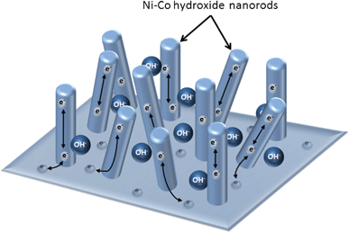
Based on these considerations, we have adopted a simple and cost-effective chemical bath deposition (CBD) method for the direct growth of nanorod arrays of nickel-cobalt hydroxide onto a stainless steel substrate. The schematic for electrode fabrication is shown in Fig. 1. This unique design of the nanorod structure not only reduces the diffusion resistance of electrolytes in the electrode material, but also enhances its electrochemical charge–discharge. Both nickel and cobalt hydroxides are very good pseudocapacitive materials. The morphology was found to be influenced by the proportion of nickel and cobalt. Significantly, the mesoporous nickel–cobalt hydroxide nanorods exhibited a specific capacitance as high as 456 F g−1 (under a mass loading of 0.3 mg cm−2 at a scan rate of 20 mV s−1) with an energy density of 12.8 W h kg−1, as well as good cycling stability (<10% loss in capacitance after 1000 cycles), which are the important properties of supercapacitors.
 | ||
| Fig. 1 Design for nickel–cobalt binary hydroxide nanorod arrayed electrode material for supercapacitor applications. The mesoporous, hydrous architecture and metallic conductivity provide deep electrolyte penetration, as well as fast electron transport paths. | ||
The atomic weight percentage ratios of nickel nitrate and cobalt chloride were 1![[thin space (1/6-em)]](https://www.rsc.org/images/entities/char_2009.gif) :
:![[thin space (1/6-em)]](https://www.rsc.org/images/entities/char_2009.gif) 3 (N1C3), 1
3 (N1C3), 1![[thin space (1/6-em)]](https://www.rsc.org/images/entities/char_2009.gif) :
:![[thin space (1/6-em)]](https://www.rsc.org/images/entities/char_2009.gif) 2 (N1C2), 1
2 (N1C2), 1![[thin space (1/6-em)]](https://www.rsc.org/images/entities/char_2009.gif) :
:![[thin space (1/6-em)]](https://www.rsc.org/images/entities/char_2009.gif) 1 (N1C1), 2
1 (N1C1), 2![[thin space (1/6-em)]](https://www.rsc.org/images/entities/char_2009.gif) :
:![[thin space (1/6-em)]](https://www.rsc.org/images/entities/char_2009.gif) 1 (N2C1) and 3
1 (N2C1) and 3![[thin space (1/6-em)]](https://www.rsc.org/images/entities/char_2009.gif) :
:![[thin space (1/6-em)]](https://www.rsc.org/images/entities/char_2009.gif) 1 (N3C1). The aqueous solution of NH4OH was added drop-wise into the above solutions with continuous stirring until the pH reached 12. The well-polished stainless steel substrates were dipped in the resultant solution without stirring at room temperature. The solution was then heated to 70 °C and maintained at this constant temperature. When the concentration of the solubility product exceeded those of the ionic products, deposition of material occurred on the substrate surface. These films were dried and stored in an airtight container.
1 (N3C1). The aqueous solution of NH4OH was added drop-wise into the above solutions with continuous stirring until the pH reached 12. The well-polished stainless steel substrates were dipped in the resultant solution without stirring at room temperature. The solution was then heated to 70 °C and maintained at this constant temperature. When the concentration of the solubility product exceeded those of the ionic products, deposition of material occurred on the substrate surface. These films were dried and stored in an airtight container.
The pH values of the solutions were measured with a pH meter (Orion 4 star). The X-ray diffraction patterns of the samples were recorded with an X-ray powder diffractometer using Cu Kα radiation (Ultima IV, Rigaku 2500). Elemental analysis of these binary metal hydroxides was conducted using energy dispersive X-ray analysis (EDX), and the morphological analysis was performed using field emission scanning electron micrography (FESEM, Hitachi S 4800). Exact sizes and shapes of rods, as well as interplanar spacing, were determined using HRTEM analysis (HRTEM, TECNAI 20) operating at 200 kV.
The nanorod arrays grown on stainless steel substrates were directly used as working electrodes for electrochemical analysis. Cyclic voltammetric experiments (CHI 660D CH Instruments, USA) were conducted using a three-electrode mode in a 1 M KOH solution. The reference electrode and counter electrode were Ag/AgCl and platinum, respectively. Typical cyclic voltammetric curves were measured at scan rates of 20–200 mV s−1 over a voltage range of 0 and 0.45 V. The cycling behaviour was characterized up to 1000 cycles.
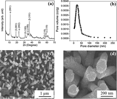
The compositions of nickel and cobalt in the prepared nickel-cobalt binary hydroxide samples are revealed using energy dispersive X-ray (EDX) analysis (Table S1, ESI†). Powder X-ray diffraction (XRD) was performed to characterize the crystalline structures of the prepared nickel-cobalt binary hydroxides. Fig. S1 (ESI†) shows XRD patterns of nickel–cobalt binary hydroxides prepared using the CBD method at 70 °C with different Ni–Co composition ratios. The nickel and cobalt peak positions are so close to each other that it is difficult to distinguish between them since, they have similar structures and diffraction peaks are very close.29,31 The XRD pattern for the nickel–cobalt hydroxide nanorods (composition N2C1) is as shown in Fig. 2a. As seen from the figure, the XRD pattern consists of a mixture of both α and β phases. It has been reported that the nanostructures of mixed-phase (α + β) powder samples exhibit superior electrochemical properties compared with those of pure α or β-phase samples.30 The XRD pattern consists of prominent peaks at 11.2° (001), 22.7° (002), 34° (100), and 59.6° (110) due to the α-phase and peaks at 19.05° (001), 32.55° (100), 38.95° (101), 51.5° (102) and 58.5° (110) due to the β-phase. The peak positions observed in the present study are in good agreement with those in previous reports.28,29,31
 | ||
| Fig. 2 (a) X-Ray diffraction pattern of nickel–cobalt binary metal hydroxide nanorods. (b) Pore size distribution of these nanorods using the NLDFT algorithm. The FESEM images of nickel–cobalt binary hydroxide nanorods (N2C1) at (c) 10 K and (d) 50 K magnifications. | ||
Brunauer–Emmett–Teller (BET) specific surface area measurements have been performed to measure the surface area as well as pore diameter of nickel–cobalt hydroxide nanorods. Fig. 2b shows a narrow distribution of the nonlocal density functional theory (NLDFT) pore sizes from the corresponding N2-adsorption–desorption isotherm.35,36 The majority of the pores fall in the optimal range 20–250 nm, with a BJH pore volume 0.127 cc g−1, indicating that pores of nickel–cobalt hydroxide nanorods are mainly mesoporous and microporous.3 Fig. S2† shows the nitrogen adsorption–desorption isotherms of the Ni–Co hydroxide nanorods. The BET surface area of the Ni–Co hydroxide nanorods is 117 m2g−1. Note that the highly porous structure and high surface area of the electrode material are beneficial to supercapacitor performance because the ion transfer rate in a porous system, and the extent of electrode/electrolyte interfacial area, are determined by the porosity of the electrode material.
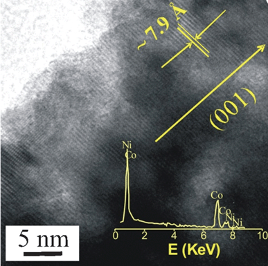
The surface morphological studies of the binary metal hydroxide nanorods were carried out using field emission scanning electron microscopy (FESEM). Fig. 2c and 2d show FESEM images of the prepared nickel–cobalt hydroxide nanorods (sample N2C1) vertically aligned on the surface of the stainless-steel substrate. As shown in the figure, the surface of the nanorod was very rough at the edges. The nanorods were independently grown from the surface of the substrate without branching or combination with neighbouring nanorods, which is very useful for electrochemical accessibility. FESEM images of the different compositions of nickel and cobalt (N1C1, N3C1, N1C3, and N1C2) are shown in Fig. S3 (ESI†). The images reveal that a highly oriented and porous morphology can be obtained only with N2C1, which will be useful in supercapacitor applications. The high-resolution transmission electron microscopy (HRTEM) image is shown in Fig. 3. The interplanar spacing of a crystalline grain was calculated to be ∼7.9 Å, corresponding to a (001) atomic plane orientation, α phase (11.2°). The inset of Fig. 3 shows EDX analysis of a single nanorod, which confirms that nanorod contains both nickel and cobalt. Fig. S4 (ESI†) shows bright field transmission electron microscopy (TEM) images of the N2C1 sample, highlighting the sizes and shapes of the nanorods. The mean diameter of the rod was about 150 nm (± 40 nm) and the length of the rod was about 1.5 μm (± 0.3 μm).
 | ||
| Fig. 3 High-resolution TEM images of the nickel–cobalt binary metal hydroxide nanorod. The inset shows the EDX pattern of a single rod, indicating the presence of both nickel and cobalt. | ||
Cyclic voltammogram (CV) studies were employed to characterize the capacitive performances of the nickel–cobalt hydroxide nanorods. In the case of a nickel–cobalt hydroxide sample with a nickel–cobalt composition ratio of 2![[thin space (1/6-em)]](https://www.rsc.org/images/entities/char_2009.gif) :
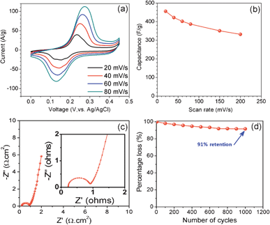
:![[thin space (1/6-em)]](https://www.rsc.org/images/entities/char_2009.gif) 1 (sample N2C1), the oxidation and reduction peaks appeared at 0.23 and 0.15 V, respectively. Fig. 4a shows the CVs of the nickel–cobalt hydroxide nanorod (N2C1 sample, at a mass loading of 0.3 mg cm−2) in 1 M KOH electrolyte at different scan rates in the range 20–80 mV s−1. As seen in the figure, the CVs are almost symmetric, indicating good reversibility of the oxidation and reduction processes. The CVs show a broad redox peak due to faradic reactions of cobalt hydroxide and nickel hydroxide.29
1 (sample N2C1), the oxidation and reduction peaks appeared at 0.23 and 0.15 V, respectively. Fig. 4a shows the CVs of the nickel–cobalt hydroxide nanorod (N2C1 sample, at a mass loading of 0.3 mg cm−2) in 1 M KOH electrolyte at different scan rates in the range 20–80 mV s−1. As seen in the figure, the CVs are almost symmetric, indicating good reversibility of the oxidation and reduction processes. The CVs show a broad redox peak due to faradic reactions of cobalt hydroxide and nickel hydroxide.29
| Co(OH)2 + OH− ↔ CoOOH + H2O + e− | (1) |
| CoOOH + OH− ↔ CoO2 + H2O + e− | (2) |
| Ni(OH)2 + OH− ↔ NiOOH + H2O + e− | (3) |
 | ||
| Fig. 4 (a) Cyclic voltammogram curve at various scan rates of 20, 40, 60 and 80 mV s−1 for the nickel-cobalt nanorod arrays. (b) Variation of the specific capacitance for different scan rates. (c) Nyquist plot of nickel–cobalt binary metal hydroxide nanorod arrays. (d) Cycling stability of the binary hydroxide nanorod arrays. | ||
The specific capacitance (Csp) of the electrode can be calculated using the equation,
 | (4) |
The decrease in the capacitance with scan rate is due to significant barriers to the penetration and diffusion of electrolytes. This is a common issue for all electrochemical supercapacitors. The loss of specific capacitance up to 60–85% for scan rates in the range 2–100 mVs−1 has been observed in some previous studies. The loss can be very serious at high mass loadings. In our case, however, only about 30% of the decrease in specific capacitance was observed when the scan rate was increased from 20 to 200 mV s−1 (Fig. 4b). This result can be attributed to the 3D nanorod array structures which can reduce the diffusion resistance of protons and enhance ion transport during the charge-discharge process at high scan rates.
The energy density (ED) can be calculated from cyclic voltammetry data using the following equation,
 | (5) |
Electrochemical impedance spectroscopy (EIS) measurements were performed to quantitatively evaluate electrical resistance which is an important aspect of a supercapacitor electrode. Fig. 4c shows the Nyquist plot of nanorod arrays (N2C1) measured at open circuit potential in the frequency range between 1 Hz to 1 MHz. The plot consists of a semicircle at the high-frequency region which is related to Faradic reactions and a straight line at low-frequency region. A near vertical straight line (∼80°) at low frequencies suggests blocking electrode behaviour. This very steep spike shows that kinetics of ion diffusion in the solution as well as adsorption of ions onto the electrode surface occurs swiftly. Therefore, the Warburg impedance which is related to the diffusion of ions within the pores of electrode is negligible. The internal solution resistance RS of 0.2 Ω and the charge transfer resistance Rct of 0.7 Ω can be estimated for the N2C1 sample. The resistance value obtained in the present study was lower than that in the previous report for nickel–cobalt hydroxide with rough morphology.27 This is an advantage of nanorod morphology and the resulting porous space, which effectively reduces the resistance of the electrode material. It is interesting to note that pores in the nanorod network may improve the diffusivity of the electrolyte ions through the pores, reducing the series resistance (0.9 Ω) at the Ni–Co hydroxide–electrolyte interface. This shows that the electrode material used in the present study (N2C1) is highly conducting. Finally, the cycle stability, an important issue for capacitors for long-term applications, was examined. For the nickel–cobalt hydroxide nanorods, the stability is shown in Fig. 4d, illustrating excellent stability and a negligible 9% loss of specific capacitance after 1000 cycles.
Conclusions
In this communication, a new strategy for preparing binary metal hydroxide with a unique morphology was demonstrated. A low cost electrode material that is easily processed and highly porous was successfully prepared using the chemical bath deposition method. The experimental results show that the composition ratio of nickel–cobalt has a significant influence on the morphological properties. The resulting nickel–cobalt hydroxide nanorod arrays (composition N2C1) on stainless steel achieved a high specific capacitance of 456 F g−1 with an energy density of 12.8 W h kg−1. The decay in the cyclic voltammogram after the 1000 cycle test was 9%, revealing good stability of the product. This work demonstrates a design for a next-generation supercapacitor electrode material using low-cost, high performance binary hydroxide.Acknowledgements
This work was financially supported by a grant (M2009010025) from the Fundamental R&D Program for Core Technology of Materials funded by the Ministry of Knowledge Economy (MKE) and by a grant (K21003001810-11E0100-01510) from the International Research & Development Program of the National Research Foundation of Korea (NRF) funded by the Ministry of Education, Science and Technology (MEST) of Republic of Korea and the Seoul R&D Program (10919). We acknowledge helpful suggestions from Prof. Jang Myoun Ko at the Hanbat National University.References
- Y. Yang, D. Kim, M. Yang and P. Schmuki, Chem. Commun., 2011, 47, 7746 RSC
.
- F. Tao, M. Guan, Y. Zhou, L. Zhang, Z. Xu and J. Chen, Cryst. Growth Des., 2008, 8, 2157 CAS
.
- J. Xu, L. Gao, J. Cao, W. Wang and Z. Chen, J. Solid State Electrochem., 2011, 15, 2005 CrossRef CAS
.
- J. Zhang, J. Ma, L. L. Zhang, P. Guo, J. Jiang and X. S. Zhao, J. Phys. Chem. C, 2010, 114, 13608 CAS
.
- C. C. Hu, K. H. Chang, M. C. Lin and Y. T. Wu, Nano Lett., 2006, 6, 2690 CrossRef CAS
.
- J. Liu, J. Jiang, C. Cheng, H. Li, J. Zhang, H. Gong and H. J. Fan, Adv. Mater., 2011, 23, 2076 CrossRef CAS
.
- J. Zang and X. Li, J. Mater. Chem., 2011, 21, 10965 RSC
.
- P. C. Chen, G. Shen, Y. Shi, H. Chen and C. Zhou, ACS Nano, 2010, 4, 4403 CrossRef CAS
.
- C. C. Hu, C. Y. Hung, K. H. Chang and Y. L. Yang, J. Power Sources, 2011, 196, 847 CrossRef CAS
.
- F. L. Zheng, G. R. Li, Y. N. Ou, Z. L. Wang, C. Y. Su and Y. X. Tong, Chem. Commun., 2010, 46, 5021 RSC
.
- J. H. Kim, K. Zhu, Y. Yan, C. L. Perkins and A. J. Frank, Nano Lett., 2010, 10, 4099 CrossRef CAS
.
- S. G. Kandalkar, J. L. Gunjakar and C. D. Lokhande, Appl. Surf. Sci., 2008, 254, 5540 CrossRef CAS
.
- Q. Qu, P. Zhang, B. Wang, Y. Chen, S. Tian, Y. Wu and R. Holze, J. Phys. Chem. C, 2009, 113, 14020 CAS
.
- H. Wang, Q. Gao and L. Jiang, Small, 2011, 7, 2454 CAS
.
- X. Liu and P. G. Pickup, J. Power Sources, 2008, 176, 410 CrossRef CAS
.
- Z. Chen, V. Augustyn, J. Wen, Y. Zhang, M. Shen, B. Dunn and Y. Lu, Adv. Mater., 2011, 23, 791 CrossRef CAS
.
- Z. Fan, J. Yan, T. Wei, L. Zhi, G. Ning, T. Li and F. Wei, Adv. Funct. Mater., 2011, 21, 2366 CrossRef CAS
.
- X. Zhang, W. Shi, J. Zhu, D. J. Kharistal, W. Zhao, B. S. Lalia, H. H. Hng and Q. Yan, ACS Nano, 2011, 5, 2013 CrossRef CAS
.
-
B. E. Conway, Electrochemical Supercapacitors, Scientific Fundamentals and Technological Applications, Kluwer Academic/Plenum Publishers, New York, p. 15, 1999 Search PubMed
.
- K. H. Chang, C. C. Hu and C. Y. Chou, Chem. Mater., 2007, 19, 2112 CrossRef CAS
.
- C. C. Hu, W. C. Chen and K. H. Chang, J. Electrochem. Soc., 2004, 151, A281 CrossRef CAS
.
- A. Devadas, S. Baranton, T. W. Napporn and C. Coutanceau, J. Power Sources, 2011, 196, 4044 CrossRef CAS
.
- C. C. Hu, H. Y. Guo, K. H. Chang and C. C. Huang, Electrochem. Commun., 2009, 11, 1631 CrossRef CAS
.
- K. H. Chang, C. C. Hu and C. Y. Chou, Electrochim. Acta, 2009, 54, 978 CrossRef CAS
.
- T. Y. Wei, C. H. Chen, H. C. Chien, S. Y. Lu and C. C. Hu, Adv. Mater., 2010, 22, 347 CrossRef CAS
.
- T. N. Ramesh and P. V. Kamath, Electrochim. Acta, 2008, 53, 8324 CrossRef CAS
.
- S. G. Kandalker, H. M. Lee, S. H. Seo, K. Lee and C. K. Kim, J. Mater. Sci., 2011, 46, 2977 CrossRef
.
- Z. A. Hu, Y. L. Xie, Y. X. Wang, H. Y. Wu, Y. Y. Yang and Z. Y. Zhang, Electrochim. Acta, 2009, 54, 2737 CrossRef CAS
.
- V. Gupta, S. Gupta and N. Miura, J. Power Sources, 2008, 175, 680 CrossRef CAS
.
- V. Gupta, S. Gupta and N. Miura, J. Power Sources, 2009, 189, 1292 CrossRef CAS
.
- Y. Y. Liang, S. J. Bao and H. L. Li, J. Solid State Electrochem., 2007, 11, 571 CrossRef CAS
.
- J. M. Luo, B. Gao and X. G. Zhang, Mater. Res. Bull., 2008, 43, 1119 CrossRef CAS
.
- Z. Fan, J. Chen, K. Cui, F. Sun, Y. Xu and Y. Kuang, Electrochim. Acta, 2007, 52, 2959 CrossRef CAS
.
- R. R. Salunkhe, K. Jang, H. Yu, S. Yu, T. Ganesh, S. H. Han and H. Ahn, J. Alloys Compd., 2011, 509, 6677 CrossRef CAS
.
- M. Thommes, B. Smarsly, M. Groenewolt, P. Ravikovitch and A. Neimark, Langmuir, 2006, 22, 756 CrossRef CAS
.
- J. Jagiello and M. Thommes, Carbon, 2004, 42, 1227 CrossRef CAS
.
Footnote |
| † Electronic Supplementary Information (ESI) available: XRD details, nitrogen adsorption–desorption isotherms, FESEM and TEM images. See DOI: 10.1039/c2ra01220k/ |
| This journal is © The Royal Society of Chemistry 2012 |
