Tunable wave absorption properties of β-MnO2 nanorods and their application in dielectric composites
Guang-Sheng
Wang
ab,
Li-Zhou
Nie
a and
Shu-Hong
Yu
*a
aDivision of Nanomaterials and Chemistry, Hefei National Laboratory for Physical Sciences at Microscale, Department of Chemistry, Department of Materials of Science and Engineering, University of Science and Technology of China, Hefei, Anhui 230026, P. R. China. E-mail: shyu@ustc.edu.cn; Fax: +86 551 3603040
bKey Laboratory of Bio-Inspired Smart Interfacial Science and Technology of Ministry of Education, School of Chemistry and Environment, Beihang University, Beijing 100191, P. R. China
First published on 26th April 2012
Abstract
A new kind of β-MnO2 nanorod (NR)–poly(vinylidene fluoride) (PVDF) functional composite with a high dielectric constant can be prepared by addition of β-MnO2 NRs to PVDF. The microwave absorption properties of β-MnO2 NRs, which were synthesized by a simple hydrothermal method on a large scale at low temperature, have been investigated for their applications in dielectric composites. It is found that the absorbers filled with β-MnO2 NRs possess excellent microwave absorption properties, and the minimum reflection loss (RL) can be adjusted to different frequencies in the range 4–14 GHz by controlling the thickness of the β-MnO2 NR–PVDF composite. The composite has a significantly high dielectric constant and good thermal stability, with quite a low percolation threshold. The dielectric constant can reach as high as 862 when the concentration of β-MnO2 nanorod filler reaches 7 vol% at 102 Hz.
Introduction
During the last decade, with the development of 1D nanostructures, dimensionality and size of materials have also been regarded as critical factors that may bring some novel and unexpected properties. Much effort has been put into preparing MnO2 with 1D nanostructures, such as α-, β-, γ- and δ-MnO2 nanowires,1–5 β-MnO2 nanorods and nanotubes,6 and δ-MnO2 nanotubes.7 More recently, increasing interest has been focused on the applications of 1D MnO2 nanostructures, due to their low cost, abundant resources, environmentally friendly attributes and excellent electrochemical performance, influenced by the structure, morphology, and size of nanoscale MnO2, which has been one of the hot topics in this field.On the one hand, with the continually increasing demand for reduction in electromagnetic radiation and improvement of anti-electromagnetic interference, microwave absorbing materials (MAMs) with the capability to absorb electromagnetic signals are widely applied in the industrial, commercial and military fields.8–10 Thus, extensive studies of the microwave absorption properties of various materials have been undertaken to look for microwave absorbing materials with high absorptive ability and wide band absorption. The most current research focuses on electromagnetic properties in the range 2–18 GHz.11–13 Liu et al.14 obtained better microwave absorbing properties with a MAM made from paraffin wax and cross-shaped SiC fibers. The optimum reflection loss was −28.47 dB at 12 GHz. Fan et al.15 reported that the RL peak value of flaky graphite that was milled for 12 h was −25.5 dB at about 14.4 GHz. Yu et al.16 found that the foam composite absorbers filled with carbonyl iron fiber exhibited good microwave absorbing properties in the frequency range 8–18 GHz. Feng et al.17 reported that the flaky Ni(Fe) alloy showed good microwave absorbing properties at the frequency −23.8 dB and 0.8 GHz. Many one-dimensional nanostructures, such as carbon nanotubes,18,19 Fe encapsulated within carbon nanotubes,20–22 ZnO nanostructures,23–26 CdS/α-Fe2O3 heterostructures,27 and β-MnO2 nanorods28 have been attracting great interest for their use as microwave absorbing materials.
On the other hand, some metal oxide nanoparticles (ZnO, TiO2, NiO), studied as conductive-filler in polymers29,30 for polymer–matrix composites with a high dielectric permittivity, have received increasing interest recently for various potential applications in high charge-storage capacitors.31 A wide variety of high dielectric constant composite materials has been developed. Currently, two methods are employed for improving the dielectric constant of the polymers. One is to disperse some ferroelectric ceramic powders into the polymer to form 0–3 type composites. Traditional ceramics, e.g. BaTiO3, BaSrTiO3, PbZrTiO3, and CCTO, have been actively explored as fillers.32–34 The effective dielectric constant of the ferroelectric ceramic–polymer composites increases with the volume fraction of the ceramics based on the mixing rules, while the dielectric constant of these polymer–ceramic composites developed to date is either below 100 or high but with a high filler content at room temperature.
Other significant efforts have focused on developing percolative composites. Conductive filler–polymer composites are another approach towards high dielectric constant materials, and are a kind of conductor–insulator composite based on percolation theory. Ultra-high dielectric constants can be expected with conductive filler–polymer composites when the concentration of the conductive filler is approaching the percolation threshold. Also, this percolative approach requires a much lower volume concentration of filler, compared to the traditional approach of high dielectric constant particles in a polymer matrix. Therefore, this material option represents advantageous characteristics over the conventional ceramic–polymer composites. The ZnO–polymer or TiO2–polymer composites were always thought of as materials with low dielectric constants. New insights into the unique properties of the 1D nanoparticle filler and polymer matrix have been gained in the most recent studies,29,30 which also confirm the advantages of 1D semiconductor nanomaterials in a dielectric field.
In this article, we report the wave absorption properties of β-MnO2 nanorods (NRs) synthesized by a simple hydrothermal process, as well as their application in dielectric composites. The results demonstrated that the β-MnO2 NRs can be combined with poly(vinylidene fluoride) (PVDF) to fabricate a dielectric composite with high dielectric constants, good thermal stability and quite a low percolation threshold, which can act as a promising dielectric composite with a high dielectric constant and low inorganic filler content.
Experimental
All the reagents (analytical-grade purity) were purchased from Shanghai Chemical Reagents Co. and used without further purification.Preparation of β-MnO2 NRs
(NH4)2S2O8 was used as an oxidizer for MnSO4 in this method. For a typical synthesis, MnSO4·H2O (0.01 mol) and an equal amount of ammonium persulfate ((NH4)2S2O8) were added into 80 mL distilled water at room temperature to form a homogeneous solution, which was then transferred into a Teflon-lined stainless steel autoclave with a volume of 100 mL, sealed and maintained at 140 °C for 12 h. After the reaction was completed, the resulting solid product was filtered, washed with distilled water to remove ions possibly remnant in the final products, and finally dried in air at 120 °C.Preparation of β-MnO2 NR–PVDF nanocomposites
The desired amount of β-MnO2 was first ultrasonically dispersed in 200 mL of N,N-dimethylformamide (DMF) for 1 h. Then, poly(vinylidene fluoride) (PVDF) was added into the β-MnO2 suspension. After stirring for 60 min at 80 °C and ultrasonication for another 3 h, the mixture was poured onto a glass plate to form a thin film, and dried at 70 °C for 3 days. The samples for testing were made by hot-pressing several solution-cast films stacked together at 200 °C.Characterization
The samples were characterized by X-ray diffraction (XRD), recorded on an (Philips X'Pert Pro Super) X-ray powder diffractometer with Cu KR radiation (λ = 0.154056 nm). The grain morphology and size were observed by sputtering with gold for scanning electron microscopy (SEM) on a KYKY-1010B microscope and field emission scanning electron microscopy (FE-SEM) on a JSM-6700F microscope. Transmission electron microscopy (TEM) and high-resolution TEM (HRTEM) investigations were carried out by a JEOL TEM-2100F microscope. The dielectric properties were measured by an HP 4294A Impedance meter in the frequency range of 10–100 MHz at room temperature and at temperatures ranging from 20 to 150 °C.Results and discussion
Preparation and characterization of the β-MnO2 NRs
The phase and purity of the as-obtained product were examined by the XRD pattern shown in Fig. 1. All of the diffraction peaks of the product can be exclusively indexed to a pure tetragonal phase of β-MnO2 (JCPDS Card, no. 24-0735, a = 4.399 Å and c = 2.874 Å). No peaks for other phases were observed, indicating its high purity and crystallinity.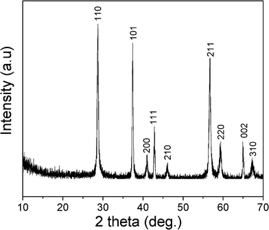 | ||
| Fig. 1 XRD pattern of the synthesized β-MnO2 NRs. | ||
A general overview of the product indicates that the sample consists of uniform NRs as shown in a scanning electron microscopy (SEM) image (Fig. 2a). The highly magnified SEM image in Fig. 2b indicates that the bundle consists of uniform MnO2 NRs of 50–100 nm in diameter and 1–1.5 μm in length. Additional structural characterization of the β-MnO2 NRs is carried out using TEM and HRTEM. The TEM image in Fig. 2b shows that the MnO2 NRs have a diameter of 50–100 nm, even after a long time of ultrasonication. A typical high resolution TEM (HRTEM) image (inset in Fig. 2c), taken from the selected area marked by an arrow, reveals that the growth direction is perpendicular to that of the [110] direction. The well resolved singular spacings of 0.318 nm along the width direction confirm that the MnO2 NRs possess a single crystalline structure.
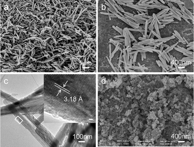 | ||
| Fig. 2 SEM images of (a), (b) as-prepared β-MnO2 NRs. (c) TEM image of the β-MnO2 NRs. Inset shows a lattice resolved HRTEM image of a single nanorod. Scale bar is 1.5 nm. (d) SEM image of the commercial bulk MnO2. | ||
Wave absorption properties
The specimens for microwave absorption properties measurement using the coaxial wire method were prepared by uniformly mixing the β-MnO2 NRs in a paraffin matrix, which is transparent to Electromagnetic (EM) waves, and pressing the mixture into a cylindrical shaped compact (Φout = 7.00 mm and Φin =3.04 mm). The relative permittivity ε values were measured in the 2–18 GHz range with an Anritsu 37269D network analyzer. The frequency dependency on the relative permittivity for paraffin wax composites, including 60 wt % β-MnO2 NRs, is shown in Fig. 3. The real permittivity ε′ slightly decreases in the frequency range 2–18 GHz, while it is clear that the imaginary permittivity ε′′ with two peaks (f1 and f2) can be observed in the current band range at about 10.7 and 14.5 GHz, respectively.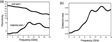 | ||
| Fig. 3 Frequency dependence of the permittivities (a) and dielectric loss (b) for the β-MnO2 NRs. | ||
Based on the data in Fig. 3a, we calculated the dielectric loss tangent tanσ (ε′′/ε′), which is shown in Fig. 3b. The dielectric loss exhibited two strong peaks at about 10.5 and 14.5 GHz, and the corresponding peak values are 0.43 and 0.45, respectively. The high dielectric loss indicates that the absorption of electromagnetic wave energy of β-MnO2 NRs might be excellent. The reflection loss (RL) of electromagnetic radiation under the normal incidence of the electromagnetic field on the surface of microwave absorbing materials backed with a conductor can be calculated as:35
 | (1) |
Here, the input impedance (Zin) is given by
 | (2) |
Thus, the theoretical reflection losses (RLs) of the composite absorber at various thicknesses can be obtained through eqn (1) and (2). Fig. 4 shows the calculated theoretical RLs of β-MnO2 NRs with different thicknesses (1–4.5 mm) in the range 2–18 GHz. It can be observed that the thicknesses of the absorbers have a great influence on the microwave absorbing properties and the minimum RLs corresponding to the maximum absorptions gradually shift toward the lower frequency; when the absorbers have a thickness of 2.5 mm, the minimum RL and the fm are −74.1 dB and 7.57 GHz, respectively, and the minimum RL can reach −44.4 dB at 13.47 GHz when the thickness is only 1.5 mm. As mentioned above, we conclude that the as-prepared β-MnO2 NRs show a better absorption performance in the range 4–14 GHz, and the minimum RL can be adjusted to different frequencies by controlling the thickness.
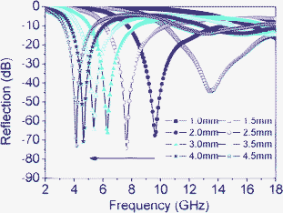 | ||
| Fig. 4 Reflection losses of NR-β-MnO2–PVDF composite absorbers at various thicknesses. | ||
Dielectric properties
To investigate how the β-MnO2 NRs affect the dielectric properties of composites, different amounts of β-MnO2 NR (NR-β-MnO2) powder were mixed with PVDF to form β-MnO2 NR–PVDF composites by a hot pressing process. Excellent dispersion of the β-MnO2 NRs and the compact structure of the polymer are shown in the SEM images of the composites in Fig. 5. The interface between the β-MnO2 NRs and the polymer was eliminated, and the β-MnO2 NRs still remained rod-shaped in the composites after hot pressing.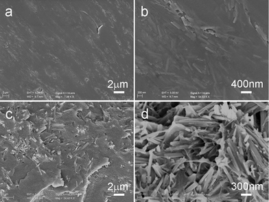 | ||
| Fig. 5 SEM images of the surface (a, b) and fractured surface (c, d) of the NR-β-MnO2–PVDF composite deposited on the wafers. The β-MnO2 NRs content is 7 vol%. | ||
For comparison, the dielectric properties of bulk MnO2–PVDF (bulk-MnO2–PVDF) composites with fc = 7 were measured at room temperature, which is shown in Fig. 6. The used bulk MnO2 consists of nanoparticles with a length of about 100–200 nm (Fig. 2c), which is nearly the same as the diameter of the prism of β-MnO2 NRs. The dielectric constants of the composites decrease with increasing frequency. The dielectric constant is about 12.8 at the frequency 102 Hz; there is no remarkable enhancement if compared with pure PVDF, which is similar to that reported for the ZnO–LDPE composite.36 The dielectric loss is no higher than 0.15 from 102 Hz to 106 Hz.
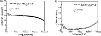 | ||
| Fig. 6 Dielectric constant and dielectric loss measured at different frequencies for the composites (bulk-MnO2–PVDF) mixed with fc = 7 at room temperature. | ||
Compared with bulk-MnO2–PVDF, the dielectric constants of the NR-β-MnO2–PVDF were greatly improved (Fig. 7a), which may be due to the rod-like nanostructures. The dipole–dipole interaction increased and contributed to the higher dielectric constant. This implies that the incorporation of β-MnO2 NRs into PVDF can effectively increase its dielectric constant. The inset in Fig. 7a shows the low percolation threshold of NR-β-MnO2–PVDF nanocomposites, at a critical filler content of 7 vol%, where the dielectric constant abruptly increases. The dielectric constant of the percolation composites reaches 862 at 102 Hz, which is 70 times higher than that of bulk-MnO2–PVDF composites with the same filler content. Compared with reported results (Table 1), the dielectric constant of NR-β-MnO2–PVDF nanocomposites is still very high.
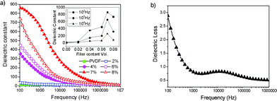 | ||
| Fig. 7 (a) Dielectric constants measured at different frequencies for the composites (NR-β-MnO2–PVDF) mixed with different volume ratios of β-MnO2 NRs (vol%) at room temperature: the dielectric constant. (b) Dielectric loss measured at different frequencies for the composites (NR-β-MnO2–PVDF) mixed with fc = 7 at room temperature. The inset in (a) shows the variation in dielectric constant of different filler contents (vol%) of β-MnO2 at frequencies of 102, 103, and 104 Hz, respectively. | ||
| Filler | Polymer-matrix | ε | tanδ | Filler loading | Filler size | Ref. |
|---|---|---|---|---|---|---|
| CCTO | PVDF | 245 (100 Hz) | 0.32 | 50% | 34 | |
| Ag | epoxy | 300 (1 kHz) | 0.05 (1 kHz) | 22% | 40 nm | 37 |
| Ag@C | epoxy | >300 (1 kHz) | >0.05 (1 kHz) | 25–30% | 80–90 nm | 38 |
| Al/Ag | epoxy | 160 (1 kHz) | 0.45 (10 kHz) | 80% Al | Ag, <20 nm | 39 |
| Al@Al2O3 | epoxy | 109 (10 kHz) | 0.02 (10 kHz) | 80% | 3.0 μm | 40 |
| Ni | PVDF | 2050 (100 Hz) | 10 (100 Hz) | 28% | 30 nm | 41 |
| BaTiO3 | epoxy | 40 (1 Hz) | 0.035 (1 Hz) | 60% | 100–200 nm | 42 |
| Ag/BaTiO3 | epoxy | 450 (1 kHz) | 0.1 (1 kHz) | Ag: 22%, BaTiO3: 30% | Ag, 40 nm | 43 |
| PANI | epoxy | 3000 (10 kHz) | <0.5 | 25% | 44 | |
| Ag/Carbon black | epoxy | 2260 (10 kHz) | 0.45 (10 kHz) | Ag: 3.7wt%, CB: 20 wt% | Ag, 13 nm | 45 |
| TEF-MWNT | PVDF | 4500 (1 kHz) | 20 (1 kHz) | 15% | 5–15 μm | 46 |
| R-ZnO/BaTiO3 | PVDF | 189 | 0.5 | 17.05% BaTiO3: 30% | BaTiO3100 nm | 30 |
The changes in dielectric constant with increasing β-MnO2 concentration can be explained by a three stage process. Firstly, the dielectric constant rises gradually as the β-MnO2 content in the composite increases, since the microcapacitance structures are formed in composites with low β-MnO2 content. Secondly, once the concentration of β-MnO2 reaches a critical volume (0.07), the percolation threshold becomes noticeable and the dielectric constant abruptly increases. At this stage, the conduction behavior of the β-MnO2–PVDF composites is also controlled by the concentration of the conducting β-MnO2 phase. Finally, the dielectric constant decreases due to the formation of a significant conductive network. This conductive network causes the composite to become the conducting material, which leads to a high leakage current within the composite, hence the dielectric constant decreases. The dielectric constant of β-MnO2–PVDF composites increases non-linearly with increasing volume ratio of β-MnO2 and reaches a maximum when the volume ratio is 0.07. Therefore, a high dielectric constant can be reached in composites containing the threshold volume of β-MnO2 NRs.
Fig. 7b shows the variation in dielectric loss with frequency. The dielectric loss of the percolation composite decreases with increasing frequency. It can be found that the dielectric loss of the percolation NR-β-MnO2–PVDF composite is 2.8 at room temperature at a frequency of 102 Hz, which is very high. Compared with the bulk-MnO2–PVDF composites, the dielectric loss increases rapidly. Usually, the introduction of inorganic semiconductor fillers to a polymer matrix enhances the dielectric loss values of the composites.47
The temperature dependence of the dielectric constant of NR-β-MnO2–PVDF composites with fc = 4 is shown in Fig. 8. Dielectric constants of the composite changing with temperature curves are consistent. At low frequency, the molecules have enough time to be polarized, for example, at 102 Hz, the dielectric constant quickly increased to above 100 °C, while, at high frequency, the polarization of molecules does not have enough time to catch up with the change in applied electrical field. The composites exhibit good thermal stability at a frequency of 104 Hz, thus the composites show a weak dependence of dielectric constant on temperature.
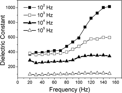 | ||
| Fig. 8 Dielectric constants for the composite (NR-β-MnO2–PVDF) mixed with fc = 4 at 102 Hz, 103 Hz, 104 Hz and 105 Hz vs. temperature. | ||
Conclusions
In summary, a new kind of β-MnO2 NR–poly(vinylidene fluoride) (PVDF) functional composite with a high dielectric constant can be prepared by addition of β-MnO2 NRs to PVDF. It is found that the absorbers filled with β-MnO2 NRs have excellent microwave absorption properties: when the thickness is 2.5 mm, the minimum reflection loss can reach −74.1 dB at 7.57 GHz, while when the thickness is only 1.5 mm, the minimum reflection loss can still be achieved to −44.4 dB at 13.47 GHz. The minimum reflection loss can be adjusted to different frequencies in the range 4–14 GHz by controlling the thickness, which is a promising microwave absorbing agent. The composites are demonstrated to have significantly high dielectric constants and good thermal stability with quite a low percolation threshold. The dielectric constant is as high as 862 when the concentration of β-MnO2 NRs filler reaches 7 vol% at 102 Hz, which is higher than that of the composites filled with metal, carbon nanofiber/nanotube and semiconductor particles, and 70 times larger than that of the bulk-MnO2–PVDF. β-MnO2 NRs can obviously enhance the dielectric constants of polymers; this also confirmed that one-dimensional nanostructures can enhance the dielectric constant of a polymer with a low percolation threshold, providing a promising filler for fabrication of a dielectric composite with a high dielectric constant and low inorganic filler content.Acknowledgements
This work was supported by the National Basic Research Program of China (Grant 2010CB934700), the funding support from the National Natural Science Foundation of China (Grants 91022032, 51102223, 21061160492, J1030412), Chinese Academy of Sciences (Grant KJZD-EW-M01-1), International Science & Technology Cooperation Program of China (Grant 2010DFA41170) and the National Science Foundation for Postdoctoral Scientists.References
- X. Wang and Y. D. Li, Chem. Commun., 2002, 764 RSC.
- X. Wang and Y. D. Li, J. Am. Chem. Soc., 2002, 124, 2880 CrossRef CAS.
- Y. J. Xiong, Y. Xie, Z. Q. Li and C. Z. Wu, Chem.–Eur. J., 2003, 9, 1645 CrossRef CAS.
- Z. Y. Yuan, Z. L. Zhang, G. D. Ren and T. B. Su, Chem. Phys. Lett., 2003, 378, 349 CrossRef CAS.
- F. A. Al-Sagheer and M. I. Zaki, Colloids Surf., A, 2000, 173, 193 CrossRef CAS.
- D. S. Zheng, S. X. Sun, W. L. Fan, H.Y. Yu, C. H. Fan, G. X. Gao, Z. L. Yin and X. Y. Song, J. Phys. Chem. B, 2005, 109, 16439 CrossRef CAS.
- X. Wang and Y. D. Li, Chem. Lett., 2004, 33, 48 CrossRef.
- G. B.Sun, B. X. Dong, M. H. Cao, B. Q. Wei and C. W. Hu, Chem. Mater., 2011, 23, 1587 Search PubMed.
- R. T. Ma, H. T. Zhao and G. Zhang, Mater. Res. Bull., 2010, 45, 1064 CrossRef CAS.
- J. Zeng and J. C. Xu, J. Alloys Compd., 2010, 493, L39–L41 CrossRef CAS.
- S. Jia, F. Luo, Q. C. Qing, W. C. Zhou and D. M. Zhu, Phys. B, 2010, 405, 3611 CrossRef CAS.
- Y. Q. Kang, M. S. Cao, J. Yuan, L. Zhang, B. Fang and X. Y. Wen, J. Alloys Compd., 2010, 495, 254 CrossRef CAS.
- X. G. Huang, J. Chen, J. Zhang, L. X. Wang and Q. T. Zhang, J. Alloys Compd., 2010, 506, 347 CrossRef CAS.
- X. G. Liu, Y. D. Wang, L. Wang, J. G. Xue and X. Y. Lan, J. Inorg. Mater., 2010, 25, 441 CrossRef CAS.
- Y. Z. Fan, H. B. Yang, M. H. Li and G. T. Zou, Mater. Chem. Phys., 2009, 115, 696 CrossRef CAS.
- M. X. Yu, X. C. Li, R. Z. Gong, Y. F. He, H. H. He and P. X. Lu, J. Alloys Compd., 2008, 456, 452 CrossRef CAS.
- J. Feng, Y. B. Liu and T. J. Qiu, J. Magn. Magn. Mater., 2011, 323, 3071 CrossRef.
- Y. L. Yang, M. C. Gupta, K. L. Dudley and R. W. Lawrence, Nano Lett., 2005, 5, 2131 CrossRef CAS.
- J. H. Wu and L. B. Kong, Appl. Phys. Lett., 2004, 84, 4956 CrossRef CAS.
- H. M. Kim, K. Kim, C. Y. Lee, J. Joo, S. J. Cho, H. S. Yoon, D. A. Pejakovic, J. W. Yoo and A. J. Epstein, Appl. Phys. Lett., 2004, 84, 589 CrossRef CAS.
- R. C. Che, L. M. Peng, X. F. Duan, Q. Chen and X. L. Liang, Adv. Mater., 2004, 16, 401 CrossRef CAS.
- R. C. Che, C. Y. Zhi, C. Y. Liang and X. G. Zhou, Appl. Phys. Lett., 2006, 88, 033105 CrossRef.
- X. Y. Fang, X. L. Shi, M. S. Cao and J. Yuan, J. Appl. Phys., 2008, 104, 096101 CrossRef.
- M. S. Cao, X. L. Shi, X. Y. Fang, H. B. Jin, Z. L. Hou and W. Zhou, Appl. Phys. Lett., 2007, 91, 203110 CrossRef.
- X. G. Liu, J. J. Jiang, D. Y. Geng, B. Q. Li, Z. Han, W. Liu and Z. D. Zhang, Appl. Phys. Lett., 2009, 94, 053119 CrossRef.
- R. F. Zhuo, H. T. Feng, J. T. Chen, D. Yan, J. J. Feng, H. J. Li, B. S. Geng, S. Cheng, X. Y. Xu and P. X. Yan, J. Phys. Chem. C, 2008, 112, 11767 CAS.
- X. L. Shi, M. S. Cao, J. Yuan, Q. L. Zhao, Y. Q. Kang, X. Y. Fang and Y. J. Chen, Appl. Phys. Lett., 2008, 93, 183118 CrossRef.
- X. L. Shi, M. S. Cao, X. Y. Fang, Y. Jie, Y. Q. Kang and W. L. Song, Appl. Phys. Lett., 2008, 93, 223112 CrossRef.
- G. S. Wang, Y. Deng and L. Guo, Chem.–Eur. J., 2010, 16, 10220 CrossRef CAS.
- G. S. Wang, ACS Appl. Mater. Interfaces, 2010, 2, 1290 CAS.
- J. X. Lu and C. P. Wong, IEEE Trans. Dielectr. Electr. Insul., 2008, 15, 1322 CrossRef CAS.
- Y. Rao, S. Ogitani, P. Kohl and C. P. Wong, J. Appl. Polym. Sci., 2002, 83, 1084 CrossRef CAS.
- Z. M. Dang, Y. H. Lin and C. W. Nan, Adv. Mater., 2003, 15, 1625 CrossRef CAS.
- M. Arbatti, X. B. Shan and Z. Y. Cheng, Adv. Mater., 2007, 19, 1369 CrossRef CAS.
- V. Sunny, P. Kurian, P. Mohanan, P. A. Joy and M. R. Anantharaman, J. Alloys Compd., 2010, 489, 297 CrossRef CAS.
- J. I. Hong, P. Winberg, L. S. Schadler and R.W. Siegel, Mater. Lett., 2005, 59, 473 CrossRef CAS.
- Q. Lai, B. I. Lee and G. J. Exarhos, Adv. Mater., 2005, 17, 1777 CrossRef.
- Y. Shen, Y. H. Lin and C. W. Nan, Adv. Funct. Mater., 2007, 17, 2405 CrossRef CAS.
- J. Lu, K. S. Moon and C. P. Wong, J. Mater. Chem., 2008, 18, 4821 RSC.
- J. Xu and C. P. Wong, Appl. Phys. Lett., 2005, 87, 082907 CrossRef.
- M. Panda, V. Srinivas and A. K. Thakur, Appl. Phys. Lett., 2008, 92, 132905 CrossRef.
- J. Wang, D. S. Wang and P. Yan, Adv. Technol. Electr. Eng. Energy, 2005, 24, 24 Search PubMed.
- Q. Lai, L. Burtran and D. William, J. Appl. Polym. Sci., 2006, 102, 967 CrossRef.
- J. Lu, K. S. Moon and C. P. Wong, Polymer, 2007, 48, 1510 CrossRef CAS.
- J. Lu, K. S. Moon, J. Xu and C. P. Wong, J. Mater. Chem., 2006, 16, 1543 RSC.
- L. Wang and Z. M. Dang, Appl. Phys. Lett., 2005, 87, 042903 CrossRef.
- S. Singha and M. J. Thomas, Trans. IEEE, IEEE Trans. Dielectr. Electr. Insul., 2008, 15, 12 CrossRef CAS.
| This journal is © The Royal Society of Chemistry 2012 |
