Sustainable processing of waste plastics to produce high yield hydrogen-rich synthesis gas and high quality carbon nanotubes†
Chunfei
Wu
a,
Zichun
Wang
b,
Leizhi
Wang
b,
Paul T.
Williams
*a and
Jun
Huang
*b
aEnergy Research Institute, University of Leeds, Leeds, United Kingdom. E-mail: p.t.williams@leeds.ac.uk; Fax: 44 113 2467310; Tel: 44 113 3432504
bLaboratory for Catalysis Engineering, School of Chemical and Biomolecular Engineering, University of Sydney, Australia. E-mail: jun.huang@sydney.edu.au; Fax: 61 2 93512854; Tel: 61 2 93517483
First published on 4th April 2012
Abstract
Gasification provides a promising alternative to thermally recycle waste plastics to produce a synthesis gas. The catalytic gasification process described here can process waste plastics to produce either a high yield, hydrogen-rich synthesis gas or high value, multi-walled carbon nano-tubes; a process that can be altered to produce the desired targeted end-product.
The total production of plastics in the world increased from 1.5 million tonnes in 1950 to 265 million tonnes in 2010 (Europe: 57 million tonnes in 2010).1 From this burgeoning use of plastics arises a plastic waste stream which requires treatment. While there is recovery of energy from plastics via municipal waste to energy plants and increases in recycling (mainly mechanical recycling), there is a significant quantity of waste plastics which are disposed of by landfill. For example in Europe 10.4 million tonnes of waste plastics were disposed by landfilling in 2010.1 This huge amount of wasted potential hydrocarbon resource attracts much research interest as waste that could be used to provide resources for a more sustainable future.
Gasification, a thermal degradation process in the presence of a limited supply of oxygen, has been known for several decades for the production of gas from coal.2 There has been recent interest in applying the technology for the gasification of wastes, including waste plastics for feedstock and energy recovery. Gasification of waste plastics produces a synthesis gas (syngas) including H2, CH4, CO and also CO2. However, the commercialization of waste plastics gasification technology could be significantly improved if the gasification process could be developed to convert all of the carbon-compounds to valuable products rather than CO2 and that the hydrogen yield could be enhanced to such an extent that a clean hydrogen fuel is produced. Catalysts are one of the key factors for maximizing the production of hydrogen from waste plastics gasification. However, deactivation of the catalyst by the deposition of coke as a carbonaceous reaction product has drawn extensive concerns,3,4 particularly as the coke cannot be avoided during the process. Here, we introduce a creative method to turn the “negative” effect of carbon deposition into a “positive” way by manipulating the formation of carbon deposition on the catalyst in the form of carbon nano-tubes (CNTs). The unique properties of CNTs will undoubtedly have many applications in the areas of electronics,5 biosensors,6 energy storage and reinforced composites for aeroplanes etc.7 Together with the production of clean H2, the added value from CNTs will provide a step change to the process of gasification of waste plastics; thus making the technology more economically feasible, environmentally friendly and resource sustainable.
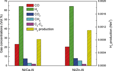
In this research, the gasification of waste polypropylene using Ni/Ca–Al and Ni/Zn–Al catalysts under steam has been carried out in a two-stage reaction system (Fig. S1, ESI†). After GC and GC-MS analysis, gas concentration and hydrogen production have been summarized in Fig. 1. The H2 concentration in the gas products reaches 64.3 vol.% during gasification at 800 °C on the Ni/Ca–Al catalyst, which relates to 0.00082 Nm3 of H2 generated from the gasification of 0.5 g of waste polypropylene. The maximum theoretical hydrogen production will be around 0.0024 Nm3 if all the hydrogen in the plastics and the maximum reacted water was converted into hydrogen gas. Thus, about 34.1 vol.% of potential hydrogen production (volume of the produced hydrogen divided by the maximum theoretical hydrogen production) was obtained in the presence of the Ni/Ca–Al catalyst.
 | ||
| Fig. 1 Gas concentration and hydrogen production for the gasification of polypropylene. | ||
At the same time, carbon filaments were generated as the coke by-product on the surface of the reacted catalyst, which have been detected by scanning electron microscopy (SEM) in Fig. 2(a). Carbon filaments with uniform diameters and reasonable length could be clearly observed on the surface of the reacted Ni/Ca–Al catalyst. Transmission electron microscopy (TEM) images shown in Fig. 2(b,c) were used to estimate that the carbon filament was about 50 nm in diameter and 10 μm in length. Graphene layers parallel to the axis of the carbon filament were observed from transmission electron microscopy (TEM) images (Fig. 2(d)) indicating that tubular multi-walled carbon nano-tubes (MWCNTs)8 were produced from the catalytic steam gasification of waste polypropylene.
 | ||
Fig. 2 Morphology of the carbon nanotubes on the surface of the 20 wt.% Ni/Ca–Al (1![[thin space (1/6-em)]](https://www.rsc.org/images/entities/char_2009.gif) : :![[thin space (1/6-em)]](https://www.rsc.org/images/entities/char_2009.gif) 1) catalyst. (a) Scanning electron microscopy at a magnification of 50 1) catalyst. (a) Scanning electron microscopy at a magnification of 50![[thin space (1/6-em)]](https://www.rsc.org/images/entities/char_2009.gif) 000; CNTs were observed on the surface of the reacted catalyst; (b), (c) and (d) transmission electron microscopy. 000; CNTs were observed on the surface of the reacted catalyst; (b), (c) and (d) transmission electron microscopy. | ||
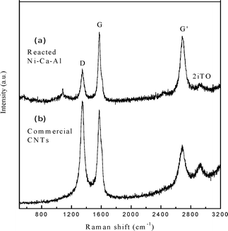
The comparison of our MWCNTs from waste polypropylene gasification and the commercial MWCNTs from Chengdu Organic Chemicals has been investigated by Raman spectroscopy and is shown in Fig. 3. The D band at around 1348 cm−1 is attributed to disordered amorphous carbon structures, while the G band at about 1571 cm−1 corresponds to tangential vibrations of the graphite carbons (i.e. crystallinity).9 The second order Raman spectrum G' band at around 2683 cm−1 is due to the two-photon elastic scattering process.10 The intensity of the D band normalized to the G band (ID/IG) is used to evaluate the degree of graphitization of CNTs. The ID/IG ratio of the CNTs from waste polypropylene gasification is 0.58, which is much lower than that of most reported CNTs (between 0.63 and 1.5)11,12 and also the commercial MWCNTs (1.14) (Fig. 3). It indicates that the highly graphitized CNTs were produced as by-products from polypropylene gasification. Furthermore, the higher intensity of the G' band (ratio of IG'/IG is around 0.94) of the CNTs from gasification demonstrates that higher purity MWCNTs were produced from this research compared with the selected commercial MWCNTs (IG'/IG ratio of 0.64 in Fig. 3). It is well known that normalization of the intensity of G' to the G band (IG'/IG) indicates the purity of CNTs, as the appearance of the G' band (two photons scattering) only happens on ordered carbons.9
 | ||
| Fig. 3 Raman spectroscopy of the carbon nanotubes on the reacted Ni/Ca–Al catalyst (a) and the commercial CNTs (b). | ||
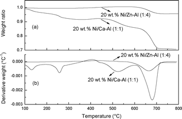
The mass of CNTs generated during gasification could be calculated by temperature programmed oxidation (TPO) of the coked catalyst. As shown in Fig. 4, the differential thermogravimetry (DTG)-TPO results show two oxidation peaks at 520 and 682 °C for the reacted Ni/Ca–Al catalyst caused by the oxidation of the amorphous carbons and the CNTs, respectively.13,14 After calculation, CNTs contributed 20 wt.% of the weight of the reacted Ni/Ca–Al samples, therefore around 0.053 g of CNTs was generated during the gasification of 0.5 g polypropylene.
Moreover, the yield of H2 and CNTs can be easily tuned by changing catalysts. The hydrogen production was enhanced from 0.00082 to 0.0011 Nm3 with a corresponding reduction of the amount of CNTs from 0.053 to 0.012 g by changing the catalyst from Ni/Ca–Al to Ni/Zn–Al for the gasification of 0.5 g polypropylene. Interestingly, both types of catalyst showed similar gas concentrations as described in Fig. 1. However, total gas yield (weight of gas divided by the weight of polypropylene) was 137.8 and 186.1 wt.% for the Ni/Ca–Al and the Ni/Zn–Al catalyst, respectively (Table S1, ESI†). Therefore, utilizing the Ni/Zn–Al catalyst to selectively promote catalytic interactions between steam and carbon-containing compounds can realize higher gas and hydrogen production with less CNT generation during the gasification of waste polypropylene, while the concentration of H2 in the gas stream remains constant.
From the results shown here it can be proposed that 1 tonne/day of CNTs (10 wt.% of the weight of the waste plastics) could be potentially generated together with H2 production around 16![[thin space (1/6-em)]](https://www.rsc.org/images/entities/char_2009.gif) 800 Nm3/day for a commercial gasification plant running with a capacity of 10 tonnes/day waste plastics. Carbon nanotubes are a very high value product with a wide range of applications. In addition, the waste plastics gasification plant using catalytic steam gasification has the potential to produce high yields of a syngas rich in hydrogen, providing an energy carrier to fuel the future. Our method also shows great flexibility for commercial application, the production of H2 and CNTs can be adjusted by simply replacing the catalysts. Without changing any other operation parameters, increasing the production of H2 or CNTs can be easily realized according to the requirements of the chemical, hydrogen and materials end-markets.
800 Nm3/day for a commercial gasification plant running with a capacity of 10 tonnes/day waste plastics. Carbon nanotubes are a very high value product with a wide range of applications. In addition, the waste plastics gasification plant using catalytic steam gasification has the potential to produce high yields of a syngas rich in hydrogen, providing an energy carrier to fuel the future. Our method also shows great flexibility for commercial application, the production of H2 and CNTs can be adjusted by simply replacing the catalysts. Without changing any other operation parameters, increasing the production of H2 or CNTs can be easily realized according to the requirements of the chemical, hydrogen and materials end-markets.
This work was supported by the UK Engineering and Physical Sciences Research Council under EPSRC Grant EP/D053110/1, the Worldwide Universities Networks (University of Leeds), International Exchange Scheme from the Royal Society (IE110273), and the Early Career Research Scheme from the University of Sydney.
References
- Plastics - the Facts 2011: An analysis of European plastics production, demand and recovery for 2010, Plastics Europe; Association of Plastics Manufacturers, Brussels, 2011 Search PubMed.
- M. W. Haenel, Angew. Chem., Int. Ed. Engl., 1988, 27, 1385–1386 CrossRef.
- J. Li, R. Yan, B. Xiao, D. T. Liang and L. Du, Environ. Sci. Technol., 2008, 42, 6224–6229 CrossRef CAS.
- M. Asadullah, S. I. Ito, K. Kunimori, M. Yamada and K. Tomishige, Environ. Sci. Technol., 2002, 36, 4476–4481 CrossRef CAS.
- W. Liang, M. Bockrath, D. Bozovic, J. H. Hafner, M. Tinkham and H. Park, Nature, 2001, 411, 665–669 CrossRef CAS.
- W. Yang, K. R. Ratinac, S. P. Ringer, P. Thordarson, J. J. Gooding and F. Braet, Angew. Chem., Int. Ed., 2010, 49, 2114–2138 CrossRef CAS.
- R. H. Baughman, A. A. Zakhidov and W. A. de Heer, Science, 2002, 297, 787–792 CrossRef CAS.
- S. Iijima, Nature, 1991, 354, 56–58 CrossRef CAS.
- R. A. DiLeo, B. J. Landi and R. P. Raffaelle, J. Appl. Phys., 2007, 101, 064307 CrossRef.
- R. Saito, A. Gruneis, G. G. Samsonidze, V. W. Brar, G. Dresselhaus, M. S. Dresselhaus, A. Jorio, L. G. Cancado, C. Fantini, M. A. Pimenta and A. G. Souza, New J. Phys., 2003, 5, 157 CrossRef.
- M. G. Donato, S. Galvagno, G. Messina, C. Milone, A. Pistone and S. Santangelo, Diamond Relat. Mater., 2007, 16, 1095–1100 CrossRef CAS.
- S. Cui, R. Canet, A. Derre, M. Couzi and P. Delhaes, Carbon, 2003, 41, 797–809 CrossRef CAS.
- C. Wu and P. T. Williams, Appl. Catal., B, 2010, 96, 198–207 CrossRef CAS.
- J. H. Lehman, M. Terrones, E. Mansfield, K. E. Hurst and V. Meunier, Carbon, 2011, 49, 2581–2602 CrossRef CAS.
Footnote |
| † Electronic Supplementary Information (ESI) available: Experimental procedures and preparation of catalysts. See DOI: 10.1039/c2ra20261a/ |
| This journal is © The Royal Society of Chemistry 2012 |

