Electric-field-actuation of in situ composites that contain silver-coated carbon fibers in sodium sulfonate ionomers†
Jianguo
Tang
*a,
Bo
Yang
a,
Jixian
Liu
a,
Yao
Wang
a,
Linjun
Huang
a,
Zhen
Huang
a,
Yuan
Wang
a,
Qian
Zhu
a and
Laurence A.
Belfiore
*b
aInstitute of Hybrid Materials—the Growing Base for State Key Laboratory, Qingdao University, Qingdao 266071, PR China. E-mail: jianguotangde@hotmail.com; Fax: +86 532 85951519; Tel: +86 532 85951519
bDepartment of Chemical and Biological Engineering, Colorado State University, Fort Collins, Colorado 80523, USA. E-mail: belfiore@engr.colostate.edu; Fax: (970) 491-7369; Tel: (970) 491-5395
First published on 20th August 2012
Abstract
In this research contribution, an electric-field-stimulated actuation system was developed by impregnating sodium-sulfonated ionomers, poly(styrene-co-butyl acrylate-co-sodium allyl sulfonate, PSBS) with in situ deposited silver-modified carbon fibers (SCCF). In the actuator, PSBS acts as an electrolytic medium for metal ion migration, and the SCCFs act as surface conductive electrodes on both sides of a sandwich configuration. The maximum bending angle of 98° is achieved after 11 s of stimulation when the electric potential difference is 5 V. This novel actuator has two outstanding characteristics: (1) in situ deposited SCCFs in PSBS form double-sided surface electrodes with high conductivity (10−3 Ω cm) and good interfacial binding with the PSBS matrix, which minimizes the drawbacks of electrochemical plating or electrode-less deposition of noble metals like Pt on the membrane surface of ionic polymer metal composites (IPMCs); and (2) it has the highest bending rate compared to currently existing IPMCs including Nafion and novel ones published recently. Additionally, the storage E′ and loss E′′ moduli of the PSBS–SCCF actuation system can be adjusted by selecting the appropriate ratio of butyl acrylate to styrene, where the latter comonomer increases the rigidity of the composite. The bending angle of this actuator can be controlled by the electric potential difference, water-uptake, and terpolymer composition. This fabrication technology exhibits significant advantages, such as process simplicity using non-toxic and low cost materials, rapid response, large bending angles, and reproducibility.
1. Introduction
Various polymers, such as gels, ion-exchange membranes, and conductive materials,1–4 have been considered for applications as electro-active sensors, flexible and lightweight actuators, artificial muscles, and energy transducers. Ionic polymer metal composites (IPMCs) are a typical electro-active polymers that can convert electrical energy to mechanical energy.5 Their in situ composite characteristics of metal ions in polymer matrices make them especially promising candidates for artificial muscles because they exhibit very large bending deformations in the presence of relatively weak electric potential differences (e.g., 1–5 V).6–9 Conversely, an external mechanical force applied to the surface of IPMCs can stimulate an electrical response for application as motion sensors. Oguro et al. reported the first IPMC as an electro-active polymeric material in 1992.10 Actuators generated by IPMCs yield larger displacements than other chemical actuators, and they are lightweight, easy to produce, and generate no electromagnetic interference.Typical actuators based on IPMCs contain an ion exchange polymer layer sandwiched between metal surface electrodes.11,12 Although the actual bending mechanism of the IPMCs is the subject of current debate, it is now well-accepted that the mobility of solvated metal ion clusters in the presence of an applied electric field causes the expansion of one side of the polymer and the equivalent contraction of the other side.13 In an effort to increase the bending deformation, the most important consideration is the synthesis of ion-containing polymers that contain metal cations with good ion-exchange properties. Typical ionomers for these applications are perfluorinated alkenes with anionic-group-terminated side chains, such as Nafion™14 and Flemion™,15 or styrene-divinylbenzene-based polymers with ionic group substitution in the phenyl rings. Other polymers such as poly(styrene-alt-maleimide)-incorporated poly(vinylidene fluoride), (PSMI incorporated PVDF),16 sulfonated poly(aryletheretherketone) (SPEEK),17 and biopolymers like cellulose18 have been used as novel electro-active polymers. The ionic radii of the cations coordinated into the IPMCs must be small (i.e., similar to that of Na+, Li+, or H+) to increase the maximum bending displacement.19 Nafion, a perfluorinated ionomer that contains metal-neutralized sulfonate groups, is a typical matrix for IPMC applications. However, Nafion-based IPMCs exhibit drawbacks, such as high cost, relatively short useful lifetimes, and low blocking forces. The most significant bottleneck in the development of IPMCs for electro-active applications is the short-term loss of the inner solution via natural evaporation, leakage resulting from surface expansion, and electrolysis at the operating voltage.20 In an effort to increase the bending displacement in IMPCs, new ionomers that contain inorganic, organic, or metal nanoparticles have been developed.21–23 More recently, a novel synthesis technique has been developed to fabricate a hybrid IPMC membrane actuator capable of generating 3-dimensional (3D) kinematic motions, by controlling each individual IPMC beam.24
Additionally, the electrodes on both sides of the composite membrane play an important role in IMPC actuator performance. Usually, IMPC electrodes are generated by chemical plating techniques. For example, membranes are immersed in solutions that contain metal cations, followed by a reduction process.25 It is important to control the soaking time to avoid an electric short-circuit of the membrane. To achieve good electrodes, this soak–reduce procedure is typically repeated several times. This method is time-consuming, with low reproducibility. Hence, electro-plating is a bottleneck in fabricating IPMC actuators. A recent publication26 tended to improve the electro-plating process. Secondly, the conductivity of the actuator has an effect on the current response and the mechanical work output. Gold-implanted actuators generate a 15% higher mechanical work output despite the adverse effects on the polymer of the vacuum processing needed for the ion implantation.27 Finally, noble metals, such as gold and platinum, as original metal sources to prepare conductive electrodes, are also a problem because the plating metal layer has connection with the IPMC matrix and noble metals are expensive. Up to now, all actuators based on IPMCs use plating noble metals as 2D electrodes on both sides of the actuators.28
In this study, a new strategy to produce smart electro-sensitive actuators is discussed. The performance of the actuation device can be adjusted via the terpolymer composition. In situ deposition of silver-coated carbon fibers (SCCFs) in these ionomeric composites yields two-dimensional surface electrodes with high conductivity on both sides of actuator. The new IPMC, PSBS, can possibly replace expensive Nafion or Flemin, and the new method to prepare electrodes with high conductivity and good interfacial structure can potentially substitute plating noble metal layers.
2. Results and discussion
The new IPMC (PSBS), sodium-sulfonated ionomer, consists of styrene, butyl acrylate and sodium allyl sulfonate monomers. Each monomer plays a different role in the IPMC. Styrene makes the IPMC rigid, butyl acrylate makes it flexible for easy deformation, and sodium allyl sulfonate makes it water-absorbent. By adjusting the content of each component in this copolymer, we can modulate the corresponding properties. This IPMC actuator was fabricated by doping PSBS films with silver-modified carbon fibers (SCCFs). The SCCFs are illustrated in Fig. 1Avia SEM. The crystal structure of the silver sheath deposited on these fibers was confirmed via wide-angle X-ray diffraction (WXRD) in Fig. 1B at 2θ = 38.0°, 44.2°, 64.4°, and 77.34°, corresponding to the (111), (200), (220) and (311) planes of silver, respectively. The carbon fibers are completely amorphous, due to the lack of a crystallographic reflection at 2θ = 26°. The electron micrograph in Fig. 1C reveals PSBS nanospheres with diameters of 50 nm, representing the original state of PSBS synthesized by emulsion polymerization. An actuator membrane that contains SCCFs in PSBS is illustrated via SEM in Fig. 1D. This two-layer film reveals a “lower layer” with a high loading of SCCF and an “upper layer” that is composed primarily of PSBS. The ratio of the thicknesses of the two layers is approximately 1![[thin space (1/6-em)]](https://www.rsc.org/images/entities/char_2009.gif) :
:![[thin space (1/6-em)]](https://www.rsc.org/images/entities/char_2009.gif) 1. This actuator device was made by adhering SCCF-rich surface conductive electrodes to both sides of PSBS which functions as an electrolytic medium for metal-ion migration.28
1. This actuator device was made by adhering SCCF-rich surface conductive electrodes to both sides of PSBS which functions as an electrolytic medium for metal-ion migration.28
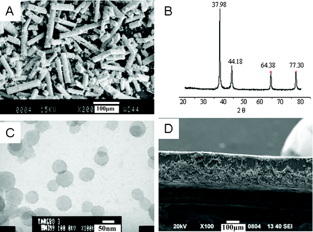 | ||
| Fig. 1 The morphological structures of PSBS, SCCF, and the PSBS–SCCF film. (A) An SEM image of SCCF, (B) a WAXD diffractogram of SCCFs, (C) a TEM image of PSBS latex, and (D) the PSBS–SCCF film that represents one-half of the actuator membrane. | ||
Fig. 2A illustrates bending displacement photographs at 1-second intervals for an IPMC actuator that is stimulated by a 5-volt electric potential difference. Fig. 2B reveals a schematic diagram of the bending process in which θ is the bending angle. This IPMC actuator achieves an equilibrium bending angle of 98° that is achieved after 11 s of electric-field stimulation, as photographically shown in Fig. 2A. It is important to emphasize that the actuator does not revert to its original undeformed state when the electric potential difference is removed. An equivalent 5-volt reversed-bias potential difference is required to null the bending displacement. Fig. 2C shows the experimental data (black squares) and provides a quantitative relationship between the bending angle vs. time (red line, calculated with eqn (1)) when the actuator is stimulated by a 5-volt potential difference. After checking the recent publications,29–31 we found the bending rates indicated in Fig. 2C are prodigiously fast. For example, C. M. Koo and coworkers29 reported an ionic thermoplastic elastomer, poly((t-butyl-styrene)-b-(ethylene-r-propylene)-b-(styrene-r-styrene sulfonate)-b-(ethylene-r-propylene)-b-(t-butyl-styrene)) (tBS-EP-SS-EP-tBS; SESPB) pentablock copolymer, and its nanocomposites with sulfonated montmorillonite (s-MMT) as polymer electrolytes for ionic polymer–metal composite (IPMC) actuators. In Fig. 4(b) and (c)29 they presented the time-dependent bending deformations of the IPMCs under identical DC potential. At the 10th second, Nafion reached a maximum with 12 mm deformation, but SESPB–s-MMT reached its maximum with 11 mm at the 120th second. Obviously, the bending rate of the SESPB pentablock copolymer is very slow. C. -A. Dai et al.30 reported a polymer actuator based on a PVA–PAMPS ionic membrane, the tip displacements in the bending angle were 45° at the 120th second and 85° at the 240th second. Y. -T. Yoo and coworkers reported a sulfonated polystyrene-based ionic polymer–metal composite (IPMC) actuator.31 They gave comparisons with Nafion and their IPMC, which needed 51 s and 40 s for the same bending angles to 45°, respectively. Therefore, we can conclude that we have obtained the fastest deformation rate for our actuator and this bending property is even better than that of Nafion.
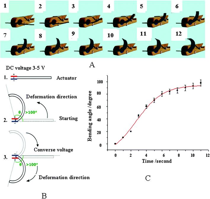 | ||
| Fig. 2 Photograph indications of the actual displacement in the PSBS–SCCF actuator (A), a schematic definition of the bending angle (B), and the quantitative relationship between the bending angle vs. time (C), data taken from the photographs in (A). The best set of model parameters in eqn (1) that match the experimental bending angle data in (C) are: A1 = −21°, A2 = 94°, t0 = 2.7 s, d = 1.7 s. | ||
Predicting the electro-mechanical behavior of ionic polymer metal composites (IPMCs) is important in many actuator design applications, but a general model for such predictions has not been successfully developed yet.32 This study shows that the proposed modeling method is simple but general enough to simulate the deformation characteristics of IPMC actuators of various sizes. The Boltzmann function given in eqn (1) was chosen to describe the experimental bending angle data,

| (1) |
The dynamic mechanical analysis of PSBS without silver-coated carbon fibers is illustrated in Fig. 3A(1–3), from −60 °C to 100 °C. These data reveal the storage E′ and loss E′′ moduli in the bending mode [Fig. 3A(1) and 3A(2)]. The loss tangent data in Fig. 3A(3) indicate that the glass transition temperature of the ionic terpolymer is 41 °C at full solid state, that means that the deformation of PSBS is feasible when it fully absorbs water. The elemental analysis of PSBS via energy dispersive spectroscopy is illustrated in Fig. 3B, revealing that the mass fraction of Na+ in PSBS is 1.16%. The solvated Na+ ions in PSBS migrate in the presence of an applied electric field and cause the expansion of one side of the PSBS membrane and the equivalent contraction of the other side.13 Actually, the actuation performance of PSBS–SCCF is affected by (i) the water content, (ii) the ionic exchange capacity, (iii) the conductivity of the surface electrodes, and (iv) the electric potential difference.
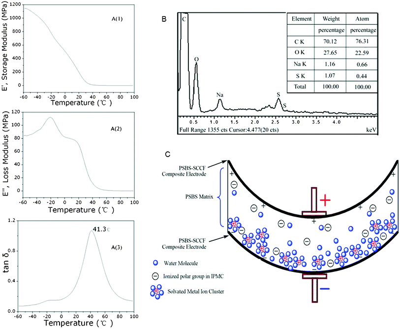 | ||
| Fig. 3 Dynamic mechanical analysis (DMA) of PSBS without SCCF (A), elemental analysis of PSBS via energy dispersive spectroscopy (B), and schematic indication of ion migration and the caused bending of PSBS membrane (C). | ||
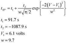
As an example, the effect of the applied electric potential difference on the time required to achieve a bending displacement of 45° is illustrated in Fig. 4. The optimum potential difference is approximately 6.1 volts, which induces a maximum average rate of bending between 0° and 45°, requiring approximately 2.2 s to achieve a bending displacement of 45°. Potential differences greater than 6.1 volts might induce hydrolysis reactions in PSBS. The experimental data in Fig. 4 were matched to the following Gaussian function:
 | (2) |
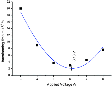 | ||
| Fig. 4 The influence of potential difference V on time (in seconds) required to achieve a 45° bending displacement. Experimental data; t45°vs. V, were matched to eqn (2). | ||
Shoji and Hirayama35 investigated the influence of environmental humidity on the performance of perfluorinated-ionomer-platinum/Li+-based actuators and suggested that a relative humidity near 50–60% produces a maximum bending displacement. Perfluorinated ionomers absorb approximately 5 wt.% moisture.26 Hence, this result is significantly lower than the moisture-content data in Table 1 and Fig. 5, as discussed below.
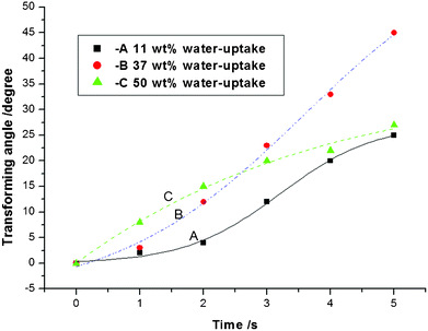 | ||
| Fig. 5 The influence of the PSBS water content on the bending deformation of PSBS–SCCF composites in response to an applied electric potential difference of 5 V. | ||
| Thickness (mm) | Water-uptake ratio (%) |
|---|---|
| 0.2 | 63 |
| 0.5 | 54 |
| 1 | 46 |
| 1.5 | 36 |
Water absorption by polymeric membranes is an important design consideration for electro-sensitive actuators because it determines the (i) volume of the swollen matrix, (ii) the diffusion coefficients for the encapsulated cations, (iii) the dielectric permeability of the matrix and the corresponding internal electric fields that develop in response to externally applied electric potential differences, and (iv) the overall actuator performance. As reported in Table 1, the swelling ratio of PSBS decreases in thicker films.
The transient actuator response in Fig. 5 reveals the effect of the PSBS water content on the bending deformation of PSBS–SCCF electro-sensitive composites when the external potential difference is 5 V. The best response (i.e., 5 s required to achieve a bending angle of 45°) was obtained in PSBS–SCCF composites that contained 37% water.
The ionic exchange capacity (IEC) of PSBS reflects ion migration that is governed by the ionization activation energy between sodium cations and sulfonic acid groups in sodium allyl sulfonate. Initially, PSBS of known mass was immersed in 0.1 mol L−1 HCl for 24 h to achieve H+ equilibration in the film, which was subsequently removed from the acid solution and washed with deionized water. Next, the film was immersed in 0.1 mol L−1 NaCl for 24 h to initiate the exchange of H+ with Na+. IEC was calculated via titration with 0.1 mol L−1 NaOH, using phenolphthalein as an indicator. This procedure yielded IEC = 0.23 mmol g−1 for PSBS, according to eqn (4) in the experimental section.
The conductivity of surface electrodes on both sides of the SCCF–PSBS–SCCF sandwich is the most important factor that governs actuator performance. According to the surface resistivity data in Table 2, larger mass fractions of SCCF in the ionic terpolymer increases the conductivity by a few orders of magnitude, approaching the conductivity of metals. This significant increase in the conductivity of PSBS–SCCF IPMCs is greater than that for similar wt. fractions of graphene (i.e., 2-dimensional crystalline sheets of sp2 carbons) in PSBS. The morphological structure of PSBS films with graphene electrodes is illustrated in Fig. 6, revealing that graphene does not exhibit a “rolled-out” conformation in the polymer matrix, most likely due to large interfacial stresses that cause a decrease in conductivity. Bockrath and coworkers36 measured a surface resistivity of 104 Ω cm for single-walled carbon nanotubes with high length-to-diameter ratios. In general, the large bending stiffness of carbon nanotubes precludes their use as potential surface electrodes in IPMC actuation systems. Layers with low surface resistivity facilitate a constant electric potential difference across the thickness of the actuator, along its entire length. However, several studies have demonstrated that fatigue and cracking in the electro-deposited metal layer increases the conductivity of PSBS–SCCF IPMCs and is greater than that for similar wt. fractions of graphene (i.e., 2-dimensional crystalline sheets of sp2 carbons) in PSBS.
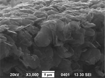 | ||
| Fig. 6 A cross-sectional SEM image of hybrid PSBS–graphene composites. | ||
| Mass fraction of conductive filler (%) | Surface resistivity, Ω cm |
|---|---|
| a The mass fraction of SCCF in PSBS is calculated according to mass, but the actual percentage in the “lower layer” of PSBS is two-folds larger. | |
| 5 wt.% SCCF in PSBSa | 2.30 × 100 |
| 15 wt.% SCCF in PSBS | 3.80 × 10⁻¹ |
| 30 wt.% SCCF in PSBS | 1.10 × 10⁻³ |
| 5 wt.% graphene | 6.67 × 10³ |
| 15 wt.% graphene | 8.03 × 10² |
| 60% expandable graphite | 1.45 × 10³ |
The electrode-less deposition of metals (e.g., Pt, Au, Pd, Cu) on membrane surfaces is a common technique to produce IPMCs.37 The design of electro-sensitive IPMC devices employs metal surface resistivity and decreases actuator performance.38,39 Cao and coworkers26 reported a surface resistivity of 105 Ω cm in Nafion–graphite-oxide nanocomposite actuators, due to the insulating characteristics of graphite oxide. Thus, in situ deposition of SCCF electrodes in PSBS electro-sensitive devices eliminates several fabrication problems, yielding surface electrodes with high conductivity and optimum bending characteristics.
The current in PSBS–SCCF actuators subjected to a 5-volt potential difference is illustrated in Fig. 7. An initial current of 140 mA decreases linearly to 5 mA over a time span of 14 s during the bending process. Current and bending motion cease in harmony, in accordance with a bending mechanism that assumes the migration of solvated-ion clusters in the presence of an electric field.
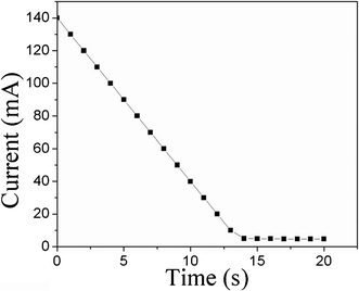 | ||
| Fig. 7 Transient current generation in PSBS–SCCF actuators during the bending process, in response to an electric potential difference of 5 volts. | ||
3. Conclusions
Electro-sensitive actuation devices have been fabricated via in situ doping of silver-modified carbon fibers (SCCFs) impregnated in sodium-sulfonated ionic terpolymers (PSBS, 1.16 wt.% Na+) with a glass transition temperature of 41 °C. A 1![[thin space (1/6-em)]](https://www.rsc.org/images/entities/char_2009.gif) :
:![[thin space (1/6-em)]](https://www.rsc.org/images/entities/char_2009.gif) 1 thickness ratio for the matrix and electrode was obtained. In the SCCF–PSBS–SCCF sandwich configuration, the ionic polymer matrix represents an electrolytic medium for metal-ion migration and both SCCF layers function as surface conductive electrodes with large interfacial contact between dissimilar layers. When these electro-sensitive actuators are subjected to a 5-volt potential difference, the maximum bending angle of 98° is achieved in approximately 10 s, and the maximum rate of bending deformation occurs approximately 3 s after electric-field stimulation is initiated. The average rate of bending deformation between 0° and 45° achieves a maximum when the potential difference across the actuator is 6.3 volts. The bending characteristics of PSBS–SCCF electro-sensitive actuators can be fine-tuned by adjusting terpolymer composition and monitoring the dynamic mechanical properties of IPMCs in the bending mode. The fabrication procedure and actuator development described in this research contribution are significantly different from electrochemical plating or electrode-less deposition of Pt or other noble metals. In situ deposition of SCCF electrodes in PSBS electro-sensitive devices eliminates problems associated with low-conductivity surface electrodes that are characteristic of electro-plating and electro-deposition processes.
1 thickness ratio for the matrix and electrode was obtained. In the SCCF–PSBS–SCCF sandwich configuration, the ionic polymer matrix represents an electrolytic medium for metal-ion migration and both SCCF layers function as surface conductive electrodes with large interfacial contact between dissimilar layers. When these electro-sensitive actuators are subjected to a 5-volt potential difference, the maximum bending angle of 98° is achieved in approximately 10 s, and the maximum rate of bending deformation occurs approximately 3 s after electric-field stimulation is initiated. The average rate of bending deformation between 0° and 45° achieves a maximum when the potential difference across the actuator is 6.3 volts. The bending characteristics of PSBS–SCCF electro-sensitive actuators can be fine-tuned by adjusting terpolymer composition and monitoring the dynamic mechanical properties of IPMCs in the bending mode. The fabrication procedure and actuator development described in this research contribution are significantly different from electrochemical plating or electrode-less deposition of Pt or other noble metals. In situ deposition of SCCF electrodes in PSBS electro-sensitive devices eliminates problems associated with low-conductivity surface electrodes that are characteristic of electro-plating and electro-deposition processes.
4. Experimental
4.1 Materials
Styrene (St, C.R.) and butyl acrylate (BA, C.R.) were purchased from Sinopharm Chemical Reagent, Beijing Co., Ltd. These monomers were purified by vacuum distillation, and refrigerated. Sodium allyl sulfonate (SAS, 90%) was purchased from Lufeng Fine Chemicals (Zibo, China). Sodium dodecyl sulfate (SDS, C.R.), ammonium persulfate (APS), and all of other inorganic chemicals were analytical grade reagents, used as received without further purification. Silver-coated carbon fibers (SCCFs) were fabricated at the Institute for Hybrid Materials, Qingdao University.4.2 Synthesis of poly(St-co-BA-co-SAS) ionic terpolymer latexes
The poly(St-co-BA-co-SAS) nano-latex was prepared by standard semi-batch emulsion polymerization, employing sodium dodecyl sulfate (SDS) as emulsifier, ammonium persulfate (APS) as initiator, and sodium bicarbonate (NaHCO3) as buffer. Initially, water (75 g), sodium allyl sulfonate (5 g), SDS (1 g), NaHCO3 (0.45 g), styrene (8 g), and butyl acrylate (12 g) were charged into a flask, which was then immersed in a water bath at 78 °C. The ratio of monomers is critical to achieve the desired performance of electro-sensitive actuators. After stirring at approximately 250 rpm for 30 min, 0.2 g of APS was introduced and polymerization occurred for 30 min. Then, drop-wise addition of styrene (8 g), butyl acrylate (12 g), and 0.2 g of APS during a time span of 1 h was followed by further polymerization for an additional 3 h. The terpolymer nano-latex, PSBS, was obtained via filtering with a final solid-content of 40 wt.%.4.3 Preparation of IPMCs
Fig. 2 provides the composition of IMPC actuators with silver modified carbon fibers. Initially, SCCFs were dispersed ultrasonically in 25 mL of PSBS. Next, the well-dispersed SCCF–PSBS latex was poured onto a glass plate and air-dried at 25 °C for approximately 30 h. The SCCF electrode settled in the lower layer of PSBS film, generating a 2-layer sandwich composed of a “lower layer” electrode and an “upper layer” electrolytic matrix. A 3-layer SCCF–PSBS–SCCF sandwich was produced by adhering two 2-layer films along their common PSBS surfaces, followed by air drying at 25 °C for approximately 30 h. The electro-sensitive actuator dimensions were 6 cm × 1 cm, with thicknesses given in Table 1.4.4 Characterization
The morphology and size of poly(St-co-BA-co-SAS) latexes were measured on an H-600 transmission electron microscope, TEM, (Hitachi, Japan). Diluted latexes were introduced onto a copper grid. For better contrast of particle edges, a small amount of phosphoric/tungsten acid was placed on the grid. The morphology of the IPMCs was obtained by scanning electronic microscopy, SEM, (Cambridge Instrument S250MK IV, Japan). SEM samples were fractured, adhered to a frame, and spattered with gold. Wide-angle X-ray diffractometry was performed on a D-8 X-ray diffractometer (Bruker, Germany). The sodium cation composition in PSBS was determined by energy dispersive spectroscopy, using the Cambridge Instrument S250MK IV SEM. The dynamic mechanical properties of the IPMCs in the bending mode at 1 Hz were obtained using a Pyris Diamond DMA (Perkin-Elmer, UK) with a Seiko Instruments analysis program. The temperature was increased from −60 °C to 100 °C at a heating rate of 3 °C min−1. The conductivity of the surface electrodes on the side of the SCCF-doped PSBS was measured on a four-probe meter, SB100A/2 (Shanghai Qianfeng electronics, Ltd.).A gravimetric method was used to determine PSBS water absorption. The swelling ratio due to water absorption was calculated according to eqn (3);
 | (3) |
The IEC was calculated according to eqn (4);
 | (4) |
Acknowledgements
The authors appreciate the financial supports from: (1) International Collaborative Program of Qingdao Science & Technology Bureau, grant #10-1-4-97-hz; (2) Natural Scientific Foundation of China (2013.01-2016.12); (3) Shandong Province Project: Tackle Key Problem in Key Technology, #2010GGX10327; (4) Program of Qingdao Science & Technology (2012-2014)..References
- Y. Osada and J. Gong, Prog. Polym. Sci., 1993, 18, 187 CrossRef CAS.
- M. E. Harmona, M. Tangb and C. W. Frank, Polymer, 2003, 44(16), 4547–4556 CrossRef.
- T.-G. Noh, Y. Tak, J.-D. Nam and H. Choi, Electrochim. Acta, 2002, 47, 2341–2346 CrossRef CAS.
- K. Jung, J. Nam and H. Choi, Sens. Actuators, A, 2003, 107, 183–192 CrossRef.
- D. Liu, A.J. McDaid, K.C. Aw and S.Q. Xie, Mechatronics, 2011, 21, 315–328 CrossRef.
- A. J. Duncan, D. J. Leo and T. E. Long, Macromolecules, 2008, 41, 7765–7775 CrossRef CAS.
- E. T. Enikov and G. S. Seo, Sens. Actuators, A, 2005, 122, 264–272 CrossRef.
- K. J. Kim and M. Shahinpoor, in Applications of polyelectrolytes in ionic polymeric sensors and artificial muscles, Handbook of Polyelectrolytes and Their Applications, ed. S. Tripathy, J. Kumar and H. S. Nalwa, American Scientific Publishers (ASP), 2002, vol. 3, ch. 1, pp. 1–22 Search PubMed.
- K. J. Kim and S. Tadokora, Electroactive Polymers for Robotic Applications, Artificial Muscles and Sensors, Springer, Berlin, 2007 Search PubMed.
- K. Oguro, Y. Kawami and H. Takenaka, J. Micro. Soc., 1992, 5, 27–30 Search PubMed.
- A. Punning, M. Kruusmaa and A. Aabloo, Sens. Actuators, A, 2007, 133, 200–209 CrossRef.
- B. Kim, D. H. Kim, J. Jung and J. O. Park, Smart Mater. Struct., 2005, 14, 1579–1585 CrossRef CAS.
- S. Feng and G. A. Voth, J. Phys. Chem. B, 2011, 115, 5903–5912 CrossRef CAS.
- K. J. Kim and M. Shahinpoor, Polymer, 2002, 43, 797–802 CrossRef CAS.
- B. Bhandari1, G.-Y. Lee and S.-H. Ahn, Int. J. Precis. Eng. Manuf., 2012, 13(1), 141–163 CrossRef.
- J. Lu, S. G. Kim, S. Lee and I. K. Oh, Adv. Funct. Mater., 2008, 18, 1290–1298 CrossRef CAS.
- X. L. Wang, I. K. Oh, J. Lu, J. J. Ju and S. W. Lee, Mater. Lett., 2007, 61, 5117–5120B CrossRef CAS.
- S. Yun and J. Kim, Synth. Met., 2008, 158, 521–526 CrossRef CAS.
- N. N. Sia and Y. Wu, J. Appl. Phys., 2003, 93(9), 5255–5267 CrossRef.
- V. K. Nguyen, J. W. Lee and Y. T. Yoo, Sens. Actuators, B, 2007, 120, 529–537 CrossRef.
- J. Y. Jung and I. K. Oh, J. Nanosci. Nanotechnol., 2007, 7, 3740–3743 CrossRef CAS.
- X. L. Wang, I. K. Oh and J. B. Kim, Compos. Sci. Technol., 2009, 69, 2098–2101 CrossRef CAS.
- J. Yeo Lee, H. S. Wang, M. J. Han, G. C. Cha, S. H. Jung, S. Lee and J. Y. Jho, Macromol. Res., 2011, 19(10), 1014–1021 CrossRef.
- H. D.Cilingir and M. Papila, Sens. Actuators, A, 2011, 168, 131–139 CrossRef.
- D. L. Wood, J. Chlistunoff, J. Majewski and R. L. Borup, J. Am. Chem. Soc., 2009, 131, 18096–18104 CrossRef CAS.
- Y. Lian, Y. Liu, T. Jiang, J. Shu, H. Lian and M. Cao, J. Phys. Chem. C, 2010, 114(21), 9659–9663 CAS.
- G. Alici, A. Punning and H. R. Sheac, Sens. Actuators, B, 2011, 157, 72–84 CrossRef CAS.
- V. Panwar, K. Cha, J. O. Park and S. Park, Sens. Actuators, B, 2012, 161, 460–470 CrossRef CAS.
- J. W. Leea, S. M. Hong, J. Kim and C. M. Koo, Sens. Actuators, B, 2012, 162, 369–376 CrossRef.
- C.-A. Dai, C.-J. Chang, A.-C. Kao, W.-B. Tsaia, W.-S. Chen, W.-M. Liu, W.-P. Shih and C.-C. Mad, Sens. Actuators, A, 2009, 155, 152–162 CrossRef.
- M. Luqman, J.-W. Lee, K.-K. Moon and Y.-T. Yoo, J. Ind. Eng. Chem., 2011, 17, 49–55 CrossRef CAS.
- J. H.Lee, J. S. Oh, G. H. Jeong, J. Yeol Lee, B. R. Yoon, J. Y. Jho and K. Rhee, Int. J. Precis. Eng. Manuf., 2011, 12(4), 737–740 CrossRef.
- B. J. Akle, M. D. Bennett and D. J. Leo, Sens. Actuators, A, 2006, 126, 173–181 CrossRef.
- B. J. Akle, D. J. Leo, M. A. Hickner and J. E. McGrath, J. Mater. Sci., 2005, 40, 3715–3724 CrossRef CAS.
- E. Shoji and D. Hirayama, J. Phys. Chem. B, 2007, 111, 11915–11920 CrossRef CAS.
- V. V. Deshpande, H.-Y. Chiu, H. W. Ch. Postma, C. Miko, L. Forro and M. Bockrath, Nano Lett., 2006, 6(6), 1092–1095 CrossRef CAS.
- A. J. Duncan, D. J. Leo and T. E. Long, Macromolecules, 2008, 41(21), 7765–7775 CrossRef CAS.
- K. J. Kim and M. Shahinpoor, Smart Mater. Struct., 2003, 12, 65–79 CrossRef CAS.
- B. Akle, S. Nawshin and D. Leo, Smart Mater. Struct., 2007, 16, S256–S261 CrossRef CAS.
Footnote |
| † Electronic Supplementary Information (ESI) available. See DOI: 10.1039/c2ra20766d |
| This journal is © The Royal Society of Chemistry 2012 |
