 Open Access Article
 This Open Access Article is licensed under a
 Creative Commons Attribution 3.0 Unported Licence
Determination of orientations of aromatic groups in self-assembled peptide fibrils by polarised Raman spectroscopy
José C.
Rodríguez-Pérez†
,
Ian W.
Hamley
and
Adam M.
Squires
*
Department of Chemistry, University of Reading, Reading, RG6 6AD, UK. E-mail: a.m.squires@reading.ac.uk
First published on 4th July 2013
Abstract
In this paper we describe a novel combination of Raman spectroscopy, isotope editing and X-ray scattering as a powerful approach to give detailed structural information on aromatic side chains in peptide fibrils. The orientation of the tyrosine residues in fibrils of the peptide YTIAALLSPYS with respect to the fibril axis has been determined from a combination of polarised Raman spectroscopy and X-ray diffraction measurements. The Raman intensity of selected tyrosine bands collected at different polarisation geometries is related to the values and orientation of the Raman tensor for those specific vibrations. Using published Raman tensor values we solved the relevant expressions for both of the two tyrosine residues present in this peptide. Ring deuteration in one of the two tyrosine side chains allowed for the calculation to be performed individually for both, by virtue of the isotopic shift that eliminates band overlapping. Sample disorder was taken into account by obtaining the distribution of orientations of the samples from X-ray diffraction experiments. The results provide previously unavailable details about the molecular conformation of this peptide, and demonstrate the value of this approach for the study of amyloid fibrils.
1 Introduction
“Amyloid” fibrils form from self-assembly of a range of different proteins and peptides. Much of the research in this area has been driven by their association with diseases such as Alzheimer's, Parkinson's, and prion disorders;1,2 in addition, fibrils may be formed in vitro by self-assembly of other proteins and designed peptides, leading to research into their potential use as nanomaterials.3,4 X-ray fiber diffraction has demonstrated a common core “cross-β” structure for many of these fibrils,5 where strands are arranged perpendicular to the fibril axis, with the beta-sheet structure stabilised by hydrogen-bonding between adjacent strands.It is very difficult to obtain more detailed structural information on polypeptide conformation within different fibrils, because in general they are not amenable to analysis by X-ray crystallography.6 Recently there have been developments in this area using solid-state NMR (ssNMR),7,8 which is capable of giving inter-atomic distances and dihedral angle constraints for molecular dynamics simulations; this has emerged as the main method to give high resolution 3D structures of peptide fibrils.
In this paper, we use a different approach based on polarised Raman spectroscopy to give detailed quantitative information on the orientation of aromatic residues within fibrils. This is particularly important, as it has been suggested that interactions between aromatic residues play an important role in amyloid fibril formation.9–12 We envisage this approach as providing complementary data to ssNMR, and moreover, it has two key advantages: firstly, our approach uses much smaller quantities of peptide or protein (0.1 mg as compared with 1–10 mg for ssNMR); and secondly, in general it does not require the use of isotope editing, unless the peptide contains more than one copy of a particular aromatic residue. Isotope labeling is a barrier to the analysis of fibrils from larger proteins, where site-specific labelling usually cannot be done. In this paper, the peptide we chose has two tyrosine residues, and we use deuteration to analyse them independently; however, had we picked another example with a single tyrosine, no labelling would have been required—a significant advantage over ssNMR, which typically requires deuteration, 13C, or 15N labelling for structural analysis of peptide fibrils.8
Linear dichroism spectroscopy is a technique performed on aligned samples to give information on the orientation of specific groups relative to the axis of sample alignment by comparing spectra obtained with light polarised parallel and perpendicular to this axis.13 Very few published examples exist of the application to amyloid fibrils of vibrational linear dichroism using polarised infrared6,14–16 or Raman17 spectroscopy, and these studies have only given broad, qualitative information on whether a particular part of the peptide is disordered, or aligned parallel or perpendicular to the fibril axis. Similar qualitative information has been obtained from linear dichroism using polarised UV/Visible spectroscopy.11,13,18–20
However, much more precise quantitative data on specific angles of orientation may in principle be obtained from polarised vibrational spectroscopy. In the case of Raman analysis, this requires knowledge of the shape of the Raman tensor for a particular normal mode of vibration, together with quantitative information on the degree of orientational sample disorder. Although such quantitative methods have not been applied to peptide fibrils before, pioneering work has been carried out by Tsuboi and co-workers on oriented samples of filamentous virus to determine the orientation of amino-acid side chains and DNA bases.21–24 However, they had no direct information on the orientational distribution of virus filaments within their samples. For liquid samples oriented by shear flow, they therefore extrapolated the data to higher shear rates to estimate the polarised Raman intensity ratio expected from perfect alignment.25 For solid samples, where this was not possible, they simply estimated the maximum error that this disorder would cause in the calculated orientation, and concluded that in their case it was small compared to other experimental uncertainties,26 making the implicit assumption of perfect order. In contrast, in this paper we demonstrate that orientational disorder may be obtained directly using X-ray scattering data, allowing us to determine a meaningful geometry of aromatic residues relative to the fibril axis, rather than an average with respect to the macroscopic sample axis.
Deuteration of amino acid side chains is a useful strategy that has been employed to aid band assignment and structural interpretation of Raman spectra,22,27–31 and represents a powerful advantage of polarised vibrational spectroscopy (infrared and Raman) over UV/Visible linear dichroism. The peptide studied in this article contains two tyrosine residues, and tyrosine ring deuteration on one of these enabled us to perform the calculations independently for each residue, since the labelled amino acid causes distinct peaks in the Raman spectra.
The peptide we chose to study in this article corresponds to residues 105–115 of the protein transthyretin, with sequence YTIAALLSPYS. Several naturally occurring mutations of the protein transthyretin are known to cause pathologies related to the formation of amyloid fibril precipitates.32 A number of amyloidogenic peptides based on its sequence have been studied to obtain clues about their structure and mechanism of fibril formation.33–36 The peptide YTIAALLSPYS has been the subject of numerous studies.35,37,38 The backbone structure of the YTIAALLSPYS strands within the aggregated fibrils was determined by magic-angle spinning solid-state NMR experiments.39,40 Fluorescence resonance energy transfer spectroscopy (FRET) was used to obtain details about the arrangement of the strands forming the fibrils as well as its aggregation process.41 The environment of the tyrosine residues of YTIAALLSPYS in solution was examined by UV resonance Raman, giving insights about the structure adopted by this peptide in the pre-aggregation stage.42 Interstrand carbonyl distances were determined from magic angle spinning (MAS) NMR.43 In previous ssNMR studies, the conformation of the tyrosine side chains in YTIAALLSPYS was not determined. Thus, in solving the molecular structure of the monomer, statistical data base restraints were used instead of experimental ones.40 We present a polarised Raman spectroscopy study on this system, with the objective of determining the orientation of these residues within the fibril.
1.1 Materials and methods
By changing the polarisation of the incident and scattered light we collected two different spectra for each sample, Icc and Ibb. The subscripts make reference to the direction of polarisation of the incident light and Raman scattering, where c is the direction of the sample/stalk axis and b perpendicular to it. No sample rotation was needed to collect the data, allowing us to keep the laser focused on the same position of the stalks when changing collection geometries. Exposure times were typically between 40 and 80 seconds at 10% laser power (30 mW at source). No fluorescence or sample heating artifacts were observed when operating at these conditions.
2 Theoretical section
The intensity of a Raman band is dictated by the extent of polarisability change with the normal coordinate of the vibration. This is given by a rank two symmetric tensor unique for each vibration, the Raman tensor. The polarised Raman scattering intensity is given by:| Iuv = I0|uTαabcv|2 | (1) |
By experimental determination or as a result of a calculation, the Raman tensor shape and orientation of its principal axes for specific vibrations can be obtained. However, to use eqn (1), the appropriate transformations of the Raman tensor from the molecular frame to the laboratory coordinate system have to be performed.53 Tensors in one coordinate system are expressed in another reference frame using the rotation matrix R whose elements are the direction cosines relating both coordinate systems:54
| αabc = RTαx′y′z′R | (2) |
We define three systems of axes to describe our experimental layout: the laboratory space-fixed axes, the fibril axes, and the molecular axes, as depicted in Fig. 1. These coordinate systems are related to each other by the Euler angles, which we defined using the same convention as Wilson, Decius and Cross.55 The laboratory and sample axes are abc, with the laser beam passing in the a direction; both incident and scattered light may be polarised in the b or c direction. The samples are aligned along the axis c, containing fibrils which are uniaxially aligned about the stalk axis. Each individual fibril makes a variable angle β with the stalk axis (coincident with c). We assume that the system has cylindrical symmetry about this axis, so the fibrils have no preferred orientation in the plane ab. The principal axes of the Raman tensors of the tyrosine side chains are x′y′z′, where the aromatic ring lies in the x′y′ plane, and the x′ axis is parallel to the phenyl C–O bond, as shown in Fig. 1. The x′y′z′ axes (molecular frame) are defined with respect to the fibril axes XYZ by the angles θ and χ. We also assume cylindrical symmetry within each fibril about the fibril axis Z, so the tyrosine side-chains have no preferred orientation in the XY plane. Because of the axial symmetry of the fibrils it is not possible to obtain information about the third Eulerian angle that would be required to fully characterise the orientation of the x′y′z′ axes.
 | ||
| Fig. 1 Euler angles relating the three coordinate systems that describe our setup. The axes abc define the laboratory frame. The stalk samples are aligned in the direction of the c axis. Individual fibrils within the stalk are distributed with cylindrical symmetry about c, making an angle β with it. The angles θ and χ define the orientation of the principal axes of the Raman tensor (x′y′z′) with respect to the fibril axes (XYZ). Figure adapted from ref. 22. | ||
If a perfect or very high degree of molecular alignment is obtained, as is the case with single crystals, it would be possible to relate the Raman tensor in the space fixed and molecular frames directly, assuming that the fibril and laboratory axes are coincident. In our case, the Raman tensor is first transformed from the molecular frame to the fibril axes, and afterwards to the laboratory frame. The expression obtained depends on the angle β, which reflects the imperfect alignment of the fibrils about the axis c. This expression is afterwards integrated for all the possible orientations about the fibril axis Z and the laboratory axis c because of the axial symmetry of the stalks and the fibrils. Each of the angular rotations needed to perform the full transformation is expressed by simple rotation matrices, and their product gives the direction cosine matrix R needed for eqn (2).54
The fibrils within the stalk samples will not be oriented at a single-valued angle β from the director; instead, they will present a distribution of orientations that has to be taken into account to relate the Raman intensities and the molecular orientations. We performed wide-angle X-ray scattering (WAXS) measurements to obtain the orientation distribution function of the fibrils within our samples, and explicitly included it in the calculations. With the orientation distribution of the fibrils, and making use of eqn (1) and (2), the polarised Raman intensity is obtained from the following expression:
 | (3) |
| Icc/Ibb = F(r1, r2, θ, χ). | (4) |
As explained elsewhere,21 if tensors for more than one Raman band for the same moiety are available, a graphical solution for the angular variables can be obtained from the experimental intensity ratios of those bands. The intersection point of the contour lines in (χ, θ) space that results from solving eqn (4) gives the angles that satisfy all the experimental intensities.
3 Results
3.1 X-ray diffraction
The X-ray diffraction pattern of Y1d4-TIAALLSPYS, shown in Fig. 2, presents the same characteristics observed previously for YTIAALLSPYS peptide fibrils.3 Meridional reflections at 4.7 Å arise from the repeating pattern of hydrogen bonded strands within the fibrils. The strands run perpendicular to the long fibril axis, forming sheets that extend alongside it. Several sheets stack together to form a fibril, at a regular spacing that gives rise to the equatorial reflection at 8.8 Å. These two reflections constitute the so called cross-β pattern, a structural characteristic shared among fibrils formed from different amyloidogenic proteins and peptides.5 We assume that the polypeptide strands that form the fibrils are perpendicular to the long fibril axis, and that therefore the order of the strands within the sample is equivalent to the order of the fibrils themselves, i.e. we assume that the distribution of orientations of the strands accurately represents the distribution of orientations of the fibrils. With this assumption, we used the meridional 4.7 Å arc to calculate the orientational distribution function of the fibrils. | ||
| Fig. 2 Wide angle X-ray diffraction pattern of Y1d4-TIAALLSPYS. The stalk sample is aligned in the vertical direction. The intense meridional reflections correspond to the regular spacing between adjacent strands in the fibril axis. | ||
The azimuthal intensity profile of the 4.7 Å reflections was background subtracted with the average of the intensity profiles immediately adjacent to it,56 and afterwards used as our input data. The calculated orientation distribution function is shown in Fig. 3. Also shown is the predicted intensity from the calculated ODF obtained from Leadbetter's expression.46 The predicted intensity fits the experimental diffraction profile accurately, indicating the adequacy of the numerical routines employed here and, more importantly, the robustness of the approach of calculating f(β) directly from the analytical solution. In terms of the order parameters usually quoted to describe sample orientation, the values obtained indicate a high degree of uniaxial alignment (P2 = 0.66, P4 = 0.3 and P6 = 0.07 average values). The average tilt angle calculated from the distribution is 29°, and integration of f(β) shows that 50% of the scatterers are within 0° < β < 29° from the director axis c, and that 90% are within 0° < β < 45°.
 | ||
| Fig. 3 Experimental and predicted intensity (left) and calculated ODF (right) for the 4.7 Å reflection of the wide angle X-ray diffraction pattern of a Y1d4-YTIAALLSPYS stalk sample. | ||
3.2 Raman spectroscopy
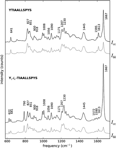 | ||
| Fig. 4 Polarised Raman spectra of peptides YTIAALLSPYS (top) and Y1d4-TIAALLSPYS (bottom). Black traces: Icc spectra. Grey traces: Ibb spectra. The spectra are offset vertically for convenience. For visualisation purposes, both unlabelled YTIAALLSPYS spectra have been scaled up to approximately match the intensity of their labelled counterparts, taking the 1445 cm−1 peak in the spectrum of Y1d4-TIAALLSPYS Icc as a reference. | ||
In principle, an estimation of the orientation of the fibrils could be obtained from the intensity ratio from this band, applying the expressions derived by Bower.65 Although this method has been employed extensively for a number of systems,66–69 certain assumptions on the symmetry of the Raman tensor are needed in order to solve the equations involved. Moreover, the information polarised Raman scattering experiments can give about f(β) is limited to the first two moments of its Legendre expansion (P2 and P4).70 We have tested the error introduced by this latter limitation by performing our calculations with the truncated orientation distribution resulting from using P2 and P4 from our X-ray data, and also using the maximum entropy distribution function70 from these two moments. Our conclusion is that the final results are only slightly affected by this approximation (results not shown). However, the assumptions about the amide I Raman tensor are not easily justifiable, since experimental studies on two different systems concluded that this tensor is not cylindrically symmetric.53,58 Indeed, in a recent polarised Raman study on the orientation of silk it was found that assuming an effective cylindrical amide I Raman tensor leads to substantial errors in the value of P4, as opposed to the value obtained when using the (non cylindrical) local tensor from other systems.71 Also, the disparities observed in the orientation distribution functions calculated from X-ray diffraction and polarised Raman spectroscopy support the conclusion that transferring the amide I effective tensor from other systems is only accurate for the first order parameter, P2.72
| ν (cm−1) | Assignment | Ref. |
|---|---|---|
| Abbreviations: st. = stretching, b. = bending, r. = rocking, def. = deformation, tw. = twisting, br. = breathing. | ||
| 2289 | Y1d4 symmetric C–D st. | 22 |
| 2274 | Y1d4 symmetric C–D st. | 22 |
| 1667 | Amide I (β-sheets) | 59 |
| 1613 | Y C2–C3, C6–C5 in-phase st., shifts to ∼1590 cm−1 on deuteration | 60, 61 |
| 1595 | Y C–C st. | 60, 61 |
| 1572 | Y1d4 C–C st. | 60 |
| 1445 | L, A, I, V C–H3 b. | 31 |
| 1345 | S, L, I C–H2 tw./r., A CαH b., CαC st. | 31 |
| 1230 | Amide III | 59 |
| 1207 | Y Cβ–Cγ st. | 60, 62 |
| 1171 | Y C–H ring b., shifts to 849 cm−1 on ring deuteration | 60 |
| 1151 | I, V CC st. | 31 |
| 1130 | L, V, I C–C st. | 31 |
| 1090 | CH3 r., Cα–Cβ st. | 59 |
| 1056 | S Cα–Cγ CH2 st. | 63 |
| 1030 | Y | 30 |
| 1008 | Y ring b. | 59 |
| 900 | P ring br. | 64 |
| 851 | Y Fermi resonance (br. mode and CCC out-of-plane b.) | 24, 59, 61 |
| 827 | Y ring br. shifts to ∼795 cm−1 on ring deuteration | 24, 59, 60 |
| 790 | Y1d4 br. | 60 |
| 641 | Y ring def. shifts to ∼620 cm−1 on ring deuteration | 60 |
| 622 | Y1d4 def. | 60 |
Raman tensors for several vibrations of L-tyrosine have been determined by Tsuboi and co-workers from polarised Raman spectroscopy measurements on single crystals of this amino acid.60 In principle, the polarised intensity ratio from all these bands could be used to determine the orientation of the tyrosine side chains in our samples. In practice, some of these tensors may not be transferable from the single crystal amino acid samples to the amyloid fibrils, since the chemical environment in both systems is likely to be different. The effect on the polarisability tensor that these differences may cause is difficult to predict. Thus, we solved our equations making use of all the available tensors and assessed the orientation information obtained on the basis of the agreement amongst the different results.
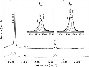 | ||
| Fig. 5 Polarised Raman spectra of Y1d4-YTIAALLSPYS in the spectral region 1500–2800 cm−1. Black trace: Icc. Grey trace: Ibb. The spectra are offset vertically for convenience. The C–D stretch vibrations appear at ∼2275 cm−1, with a higher intensity in the Ibb spectrum. Insets: C–D stretching bands at both polarisations and sub-band decomposition and fitting with Lorentzian curves. | ||
Other peaks assigned to deuterated tyrosine, in particular those at 790 and 622 cm−1, were not employed to perform the orientation calculation, because the Raman tensor is defined as the first derivative of the polarisability with respect to the normal coordinate, and therefore its specific value depends on the atomic displacements involved in each normal mode. Since atomic displacements depend on the nuclear masses of the atoms involved, tensors from non labelled molecules are generally non transferable to isotopically substituted ones.73 We therefore did not consider it valid to assume that published tensors from vibrations in non-deuterated tyrosine could also be used for their deuterated analogues.
| Y10 | Y1(d4) | |||||
|---|---|---|---|---|---|---|
| Freq. (cm−1) | 1613 | 1171 | 827 | 640 | 2289 | 2274 |
| I cc /Ibb | 0.46 | 1.52 | 0.89 | 0.83 | 0.53 | 0.55 |
| σ mean | 0.02 | 0.08 | 0.04 | 0.03 | 0.06 | 0.03 |
3.3 Orientation calculation
All the Raman tensors used in the present work have been determined by Tsuboi and co-workers from polarised Raman experiments on single crystals of tyrosine.22,60 We make the assumption that these tensors are transferable to our fibril structures, and will assess the results obtained on the basis of consistency. The precise shape and orientation of these tensors in the molecular frame are shown in Fig. 6. Because of the high symmetry of the phenolic ring most of the tensors share the same orientation of their principal axes. This system of axes is defined as follows: the axis x is parallel to the line defined by atoms C1–C4 of the tyrosine residue and the axis y is parallel to the line defined by atoms C2–C6 and intersects the axis x at the centre of the aromatic ring (apart from the vibration at 642 cm−1, where x and y are rotated by 45° in the plane of the phenolic ring); the axis z is perpendicular to both x and y (see Fig. 6). These correspond to x′, y′ and z′, respectively, in Fig. 1.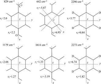 | ||
| Fig. 6 Raman tensors for the vibrational bands used in this work. These tensors have been determined by Tsuboi and co-workers from polarised Raman measurements on single crystals of L-tyrosine and L-tyrosine-2,3,5,6-d4.22,60 The local coordinate axes are indicated for each tensor, with x and y in the plane of the paper and z perpendicular to it. All the tensors present the same orientation for the molecular system of axes, except in the case of the band at 642 cm−1, which is rotated by 45° in the plane of the phenolic ring. Adapted from Tsuboi et al.22,60 | ||
Expressions for the polarised intensities Icc and Ibb were obtained by rotating the Raman tensor from the molecular to the laboratory frame, followed by an integration over the angular variables ω and σ. The orientation distribution function shown in Fig. 3 was then used to weight the Raman intensities to account for sample disorder. The ratio Icc/Ibb, needed to remove the constants present in the equations, represents the height of a surface in (χ, θ) space. The contours given by the ratio of the experimental intensities for each band were plotted; the intersection points from bands corresponding to each tyrosine residue represent the angular coordinates that satisfy all the experimental conditions.
The plots in (χ, θ) space for Y1(d4) are shown in Fig. 7 for the range 0° < χ < 180° and 0°< θ < 90°. Because eqn (1) contains powers of trigonometric terms there is no unique solution for the angular variables. For these two bands, a total of four Eulerian coordinates satisfy the experimental data: (χ1 = 26°, θ1 = 61°), (180° − χ1, θ1), (χ1, 180° − θ1) and (180° − χ1, 180° − θ1). Uncertainties in the intensity measurements of the Raman bands directly translate into uncertainties in the angular coordinates for each residue. We estimated these uncertainties by plotting the contours corresponding to the average values for the intensity ratios Icc/Ibb plus and minus one standard deviation of the mean. The possible angular values determined within experimental uncertainty lie in the area limited by these contour lines. In numerical terms, for the first solution we find (χ1 = 26° ± 3, θ1 = 61° ± 10). The uncertainties for the other three solutions are identical to the first one.
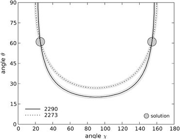 | ||
| Fig. 7 Contour plots in (χ, θ) space for tyrosine residue Y1. The lines are the locus of points that satisfy the two experimental intensity ratios obtained. Solid black line: contour of the 2290 cm−1 band; dashed line: contour of the 2273 cm−1 band. The uncertainty arising from the intensity measurements is represented by the grey lines, corresponding to the average results plus/less one standard deviation of the mean. The coordinates of the two interception points displayed here are (χ1 = 26°, θ1 = 61°) and (180° − χ1, θ1). | ||
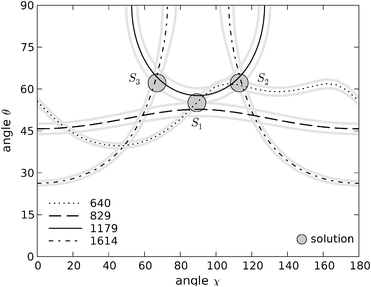 | ||
| Fig. 8 Contour plots in (χ, θ) space for tyrosine residue Y10. Solid black line: contour of the 1179 cm−1 band; dotted line: contour of the 640 cm−1 band; dashed line: contour of the 827 cm−1 band; dotted-dashed line: contour of the 1614 cm−1 band. The symmetric 640 cm−1 trace which generates solution S3 is not shown for clarity (see main text). Grey traces represent the uncertainty in the intensity measurements for each band. The coordinates of the three solutions found in this range are (χ1 = 89°, θ1 = 55°), (χ2 = 113°, θ2 = 62°) and (χ3 = 67°, θ3 = 62°). | ||
As discussed above, the principal axes of the Raman tensor for the vibration at 640 cm−1 are rotated 45° in the plane of the tyrosine ring with respect to the principal axes for the other bands. In order to obtain the contour lines in common (χ, θ) space it was necessarily to increment the values of χ by 45° for this trace.21 Since the tyrosine ring can itself be rotated about the line defined by atoms Cδ and Cζ, i.e. turned upside down, a further possible solution arises from this tensor, obtained from subtracting 45° to the calculated contour line. This additional solution, S3, is symmetric about χ = 90° with respect to (χ2, θ2) and thus have the angular coordinates (χ3 = 67°, θ3 = 62°) and (χ3, 180° − θ3). These three sets of solutions arise from the intersection of three different traces, making their individual uncertainties smaller than the solutions obtained for the labelled residue. By plotting the results obtained for the mean intensity ratio plus and less one standard deviation of the mean we conclude that the uncertainties for each solution do not exceed 2° in both χ and θ.
The existence of three different sets of points for Tyr-10 (and their symmetric counterparts at 180° − θ) may indicate that at least one of the tensors employed can not be transferred from the crystal structure to the chemical environment of our system. Unfortunately, we can not make a decision about which set of solutions is the correct one with the data available. In any case, the range of possible θ values is greatly restricted, lying between 55° ± 2 and 62° ± 2, and its symmetric counterpart region at 180° − θ, i.e. between 118° ± 2 and 125° ± 2. For the angle χ the range is broader, centred at ∼90° from 67° ± 2 to 113° ± 2.
4 Discussion
We have obtained several possible values for the orientation of the two tyrosine residues in YTIAALLSPYS amyloid fibrils. These sets of solutions are related but not entirely equivalent. However, from Raman spectroscopy measurements alone it is not possible to distinguish between them. Moreover, the axial symmetry of the samples precludes the determination of the angle ω (see Fig. 1), impeding the full characterisation of the orientation of the tyrosine rings. However, these data offer new constraints that can be used to determine the position of the tyrosine residues in this molecule, since the possible orientations they can adopt are restricted by these results.4.1 Comparison with ssNMR data
Previous ssNMR studies on YTIAALLSPYS were performed without experimental restraints for the tyrosine side chains.40 Instead, statistical database-derived data were used to limit the torsion angles of these amino acids to the values most commonly observed in proteins. A total of 20 structures were deposited in the protein data bank by Jaroniec and co-workers, representing the lowest energy solutions obtained from simulated annealing molecular dynamics calculations. For comparison purposes, we have calculated the angles χ and θ for the two tyrosine residues in the published structures of YTIAALLSPYS (PDB ID code 1RVS).40 The coordinates of the five central residues of the strand were used to define the system of axes, considering the fibril axis to be parallel to the average orientation of the carbonyl bonds.The angles χ and θ for the two tyrosine residues for each one of these structures are plotted in Fig. 9. It is clear from the figure that the possible coordinates adopted by the tyrosine rings in the fibril structure of YTIAALLSPYS do not randomly span the entirety of the solution space. Furthermore, the clusters of most frequently appearing coordinates are different for Tyr-1 and Tyr-10. The (χ, θ) coordinates for Tyr-1 are mainly concentrated in a region of low χ values (<40°) and θ angles between approximately 40° and 60°. On the other hand, the angular coordinates for Tyr-10 are more spread. Still, almost half of them appear in a region with χ values centered around 90° and θ angles between 132° and 160°. Compared to the polarised Raman data, the most frequent coordinates for Tyr-1 are in very good agreement with one of the four possible solutions consistent with our experiments. Models with tyrosine angular coordinates far off the ones we determined are in discrepancy with these data and are thus unlikely candidate structures. In the case of Tyr-10, despite the multiplicity of the solutions obtained by spectroscopic means, these require the phenolic ring of this residue to be oriented in one of two restricted regions in (χ, θ) space. This is the case with the most frequent solutions obtained by Jaroniec et al., although the θ values for these points are 10° to 40° higher than our own. The absence of points in certain regions of the (χ, θ) plot indicate that some solutions obtained from Raman spectroscopy, although numerically consistent with the data, are not feasible given the restrictions imposed by the rest of the molecule on the orientation of the phenolic rings.
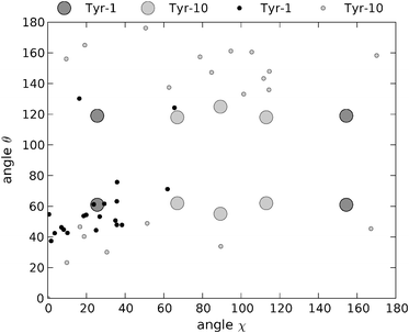 | ||
| Fig. 9 Angular χ and θ coordinates of the two tyrosine rings for the 20 minimum energy structures obtained by Jaroniec et al.40 from ssNMR measurements and subsequent molecular dynamics simulations. Black dots: Tyr-1. Grey dots: Tyr-10. Dark grey circles and light grey circles: coordinates for Tyr-1 and Tyr-10, respectively, obtained in the present work from polarised Raman measurements. | ||
4.2 Proposed coordinates from Raman spectroscopy
As discussed above, it is not possible to generate a unique solution for the orientation of the tyrosine residues from the Raman data alone. Besides, our data provide angular orientations rather than explicit cartesian coordinates, which depend on the position of the rest of the molecule. However, it is feasible to generate tyrosine coordinates consistent with our data from a starting structure. Based on the orientations obtained from the ssNMR structures, we performed rotations about the bonds Cα–Cβ and Cβ–Cγ in Tyr-1 and Tyr-10, keeping the rest of the bond angles and atomic distances constant. Given the overall good agreement between the Raman data and the ssNMR structures, only minor rotations were necessary to generate coordinates compatible with our results.As an example, we generated the model with angular coordinates (χ = 26°, θ = 61°) for Tyr-1, and (χ = 89°, θ= 125°) for Tyr-10, which is the closest to the most frequent solutions obtained by Jaroniec and co-workers. In Fig. 10, we show the resultant model for YTIAALLSPYS amyloid fibrils obtained taking the first ssNMR structure as starting point, overlayed against the rest of unmodified structures. It has to be stressed that the model shown in the figure does not represent the unique coordinates that the tyrosine residues can adopt to be in agreement with our data. It is, however, the one that required the minimum amount of rotations from this particular starting ssNMR geometry. At any rate, this is to be understood as an example of how our experiments can reduce the number of potential solutions by using these new angular restraints. New molecular dynamics calculations would be required to refine the coordinates of the whole structure taking into account these data.
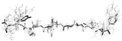 | ||
| Fig. 10 Ensemble of ssNMR structures of YTIAALLSPYS amyloid fibril strands from Jaroniec et al.40 The highlighted model corresponds to the least energy structure from ssNMR with the tyrosine rings oriented according to the polarised Raman data obtained in this work. | ||
For reference purposes, we include in Table 3 the new cartesian coordinates for the atoms in the tyrosine residues obtained from the rotations performed. The coordinates of Tyr-1 are the result of rotating −5° about the Cα–Cβ bond and 15.4° about the Cβ–Cγ bond. The coordinates of Tyr-10 were obtained by rotating 21.2° about the Cα–Cβ bond and −0.9° about the Cβ–Cγ bond.
| Tyrosine 1 | Tyrosine 10 | |||||||
|---|---|---|---|---|---|---|---|---|
| id | x | y | z | id | x | y | z | |
| id: residue index within the whole structure according to the PDB file. Only the coordinates of the atoms from the tyrosine residues with modified positions are shown, except atoms 4 and 143, which are unchanged with respect to the original PDB structure. | ||||||||
| C | 4 | −15.298 | −2.727 | 1.126 | 143 | 14.070 | 0.486 | 0.391 |
| C | 5 | −16.112 | −2.798 | 2.399 | 144 | 12.925 | 1.408 | 0.749 |
| C | 6 | −15.627 | −2.263 | 3.585 | 145 | 12.765 | 2.630 | 0.107 |
| C | 7 | −17.366 | −3.399 | 2.415 | 146 | 12.006 | 1.058 | 1.731 |
| C | 8 | −16.365 | −2.326 | 4.751 | 147 | 11.722 | 3.477 | 0.433 |
| C | 9 | −18.111 | −3.465 | 3.577 | 148 | 10.960 | 1.898 | 2.062 |
| C | 10 | −17.607 | −2.928 | 4.742 | 149 | 10.822 | 3.106 | 1.410 |
| O | 11 | −18.343 | −2.993 | 5.902 | 150 | 9.782 | 3.948 | 1.736 |
| H | 13 | −15.367 | −3.686 | 0.636 | 153 | 14.076 | −0.325 | 1.104 |
| H | 14 | −14.269 | −2.542 | 1.400 | 154 | 14.988 | 1.046 | 0.483 |
| H | 15 | −14.655 | −1.792 | 3.589 | 155 | 13.471 | 2.917 | −0.658 |
| H | 16 | −17.758 | −3.820 | 1.499 | 156 | 12.116 | 0.111 | 2.239 |
| H | 17 | −15.969 | −1.905 | 5.663 | 157 | 11.614 | 4.422 | −0.078 |
| H | 18 | −19.082 | −3.936 | 3.569 | 158 | 10.257 | 1.608 | 2.828 |
| H | 19 | −19.261 | −2.787 | 5.712 | 159 | 9.083 | 3.447 | 2.165 |
5 Conclusions
Complete structural determination of amyloid fibril systems is still a difficult task, which has only been achieved in a limited number of cases. A great array of techniques have been used to gain structural insights from amyloids, including a variety of spectroscopies, X-ray diffraction and X-ray crystallography. In the present work we have demonstrated, for the first time, the use of polarised Raman spectroscopy in combination with site-specific isotope labelling to resolve the orientation of two residues in an amyloid system. These data can be used as new restraints for molecular dynamics simulations and fine tune the molecular model of YTIAALLSPYS fibril structure.In this paper, we have used these new information to validate and refine a pre-existing model of YTIAALLSPYS fibril structure. The amino acid residues we studied are of particular importance, since it is unclear what precise role aromatic side chains play in the process of aggregation.9,10 Accurate knowledge of the aromatic rings' orientation should prove helpful to elucidate open questions such as the contribution towards overall fibril stability from these residues.
We envisage a number of ways that the technique can be employed. On its own, the polarised Raman data will typically have more than one unique orientational solution, as in the example here. However, it is likely that only one of these is energetically plausible, so computational methods can resolve this issue. Nonetheless, it is unlikely that a full peptide structure can be obtained using polarised Raman as the only experimental method; instead, it can provide previously unavailable experimental constraints, complementing other data obtained using methods such as solid state NMR and/or 2D infrared spectroscopy.
Some aspects of this technique that make it attractive include the limited amounts of material required (100 μg peptide) as compared with ssNMR and a very simple sample preparation. Since sample disorder is accounted for by using X-ray diffraction data, no exceptional high levels of fibril alignment should be required. The use of isotopic labelling is not necessary in the case of peptides with a single instance of the residue of interest, or where other strategies such as sequence mutation are employed. This is in contrast with solid-state NMR, and also with the 2D-IR methods employed by Zanni and others.74–76 This latter approach employs 13C18O labels to investigate local peptide backbone conformation, complementary to the data obtained here, on orientation of aromatic groups relative to the fibril axis.
It must be noted that these methods are not limited to the characterisation of tyrosine side chains. As long as Raman tensors for the amino acids under study are known and the relevant vibrations produce spectral bands of enough quality, the procedures we employed can be applied to other systems. Raman tensors for several moieties are already available in the literature,77 and where no experimental data exist computer calculations could provide a reasonable approximation. As such data become available, from experiments and theoretical calculations, and for a greater number of biologically important molecular fragments, we envisage our approach becoming an increasingly powerful tool for structural analysis of fibrillar bio-materials.
Acknowledgements
Thanks to Rui Guo, from the Department of Chemistry, Imperial College London, for very helpful discussions on Raman tensor analysis.References
- F. Chiti and C. M. Dobson, Annu. Rev. Biochem., 2006, 75, 336–366 CrossRef.
- I. Hamley, Angew. Chem., Int. Ed., 2007, 46, 8128–8147 CrossRef CAS.
- S. L. Gras, A. K. Tickler, A. M. Squires, G. L. Devlin, M. A. Horton, C. M. Dobson and C. E. MacPhee, Biomaterials, 2008, 29, 1553–1562 CrossRef CAS.
- J. Healy, K. Wong, E. B. Sawyer, C. Roux, L. Domigan, S. L. Gras, M. Sunde, N. G. Larsen, J. Gerrard and M. Vasudevamurthy, Biopolymers, 2012, 97, 595–606 CrossRef CAS.
- M. Sunde, L. C. Serpell, M. Bartlam, P. E. Fraser, M. B. Pepys and C. F. Blake, J. Mol. Biol., 1997, 273, 729–739 CrossRef CAS.
- J. C. Rodríguez-Pérez, I. W. Hamley and A. M. Squires, Chem. Commun., 2012, 48, 11801–11908 RSC.
- P. T. Lansbury Jr, P. R. Costa, M. G. Janet, E. J. Simon, M. Auger, K. J. Halverson, D. A. Kocisko, Z. S. Hendsch, T. T. Ashburn, R. G. S. Spencer, B. Tidor and R. G. Griffin, Nat. Struct. Biol., 1995, 2, 990–998 CrossRef CAS.
- R. Tycko, Annu. Rev. Phys. Chem., 2011, 62, 279–299 CrossRef CAS.
- E. Gazit, FASEB J., 2002, 16, 77–83 CrossRef CAS.
- F. Bemporad, N. Taddei, M. Stefani and F. Chiti, Protein Sci., 2006, 15, 862–870 CrossRef CAS.
- K. E. Marshall, M. R. Hicks, T. L. Williams, S. V. Hoffmann, A. Rodger, T. R. Dafforn and L. Serpell, Biophys. J., 2010, 98, 330–338 CrossRef CAS.
- K. E. Marshall, K. L. Morris, D. Charlton, N. OReilly, L. Lewis, H. Walden and L. C. Serpell, Biochemistry, 2011, 50, 2061–2071 CrossRef CAS.
- T. R. Dafforn and A. Rodger, Curr. Opin. Struct. Biol., 2004, 14, 541–546 CrossRef CAS.
- H. Hiramatsu, Y. Goto, H. Naiki and T. Kitagawa, J. Am. Chem. Soc., 2004, 126, 3008–3009 CrossRef CAS.
- H. Hiramatsu, M. Lu, K. Matsuo, K. Gekko, Y. Goto and T. Kitagawa, Biochemistry, 2010, 49, 743–751 CrossRef.
- J. C. Rodríguez-Pérez, I. W. Hamley and A. M. Squires, Biomacromolecules, 2011, 12, 1810–1821 CrossRef.
- I. W. Hamley, V. Castelletto, C. M. Moulton, J. C. Rodríguez-Pérez, A. M. Squires, T. Eralp, G. Held, M. Hicks and A. Rodger, J. Phys. Chem. B, 2010, 114, 8244–8254 CrossRef CAS.
- C. B. Andersen, M. R. Hicks, V. Vetri, B. Vandahl, H. Rahbek-Nielsen, H. Thøgersen, I. B. Thøgersen, J. J. Enghild, L. C. Serpell, C. Rischel and D. E. Otzen, J. Mol. Biol., 2010, 397, 932–946 CrossRef CAS.
- B. M. Bulheller, A. Rodger, M. R. Hicks, T. R. Dafforn, L. C. Serpell, K. E. Marshall, E. H. C. Bromley, P. J. S. King, K. J. Channon, D. N. Woolfson and J. D. Hirst, J. Am. Chem. Soc., 2009, 131, 13305–13314 CrossRef CAS.
- R. Adachi, K. Yamaguchi, H. Yagi, K. Sakurai, H. Naiki and Y. Goto, J. Biol. Chem., 2007, 282, 8979–8983 CrossRef.
- M. Tsuboi, S. A. Overman and G. J. Thomas, Biochemistry, 1996, 35, 10403–10410 CrossRef CAS.
- M. Tsuboi, K. Ushizawa, K. Nakamura, J. M. Benevides, S. A. Overman and G. J. J. Thomas, Biochemistry, 2001, 40, 1238–1247 CrossRef CAS.
- M. Tsuboi, S. A. Overman, K. Nakamura, A. Rodríguez-Casado and G. J. J. Thomas, Biophys. J., 2003, 34, 1969–1976 CrossRef.
- M. Tsuboi, Y. Kubo, T. Ikeda, S. A. Overman, O. Osman and G. J. J. Thomas, Biochemistry, 2003, 42, 940–950 CrossRef CAS.
- H. Takeuchi, M. Matsuno, S. A. Overman and J. G. J. Thomas, J. Am. Chem. Soc., 1996, 118, 3498–3507 CrossRef CAS.
- S. A. Overman, M. Tsuboi and G. J. J. Thomas, J. Mol. Biol., 1996, 259, 331–336 CrossRef CAS.
- J. G. J. Thomas, B. Prescott, S. J. Opella and L. A. Day, Biochemistry, 1988, 27, 4350–4357 CrossRef.
- K. L. Aubrey and G. J. J. Thomas, Biophys. J., 1991, 60, 1337–1349 CrossRef CAS.
- S. A. Overman, K. L. Aubrey, N. S. Vispo, G. Cesareni and G. J. J. Thomas, Biochemistry, 1994, 33, 1037–1042 CrossRef CAS.
- S. A. Overman and G. J. J. Thomas, Biochemistry, 1995, 34, 5440–5451 CrossRef CAS.
- S. A. Overman and G. J. J. Thomas, Biochemistry, 1999, 38, 4018–4027 CrossRef CAS.
- A. Hörnberg, T. Eneqvist, A. Olofsson, E. Lundgren and E. Sauer-Eriksson, J. Mol. Biol., 2000, 302, 649–669 CrossRef.
- A. Gustavsson, U. Engström and P. Westermark, Biochem. Biophys. Res. Commun., 1991, 29, 1159–1164 CrossRef.
- J. A. Jarvis, D. J. Craik and M. C. Wilce, Biochem. Biophys. Res. Commun., 1993, 14, 991–998 CrossRef.
- J. A. Jarvis, A. Kirkpatrick and D. J. Craik, Int. J. Pept. Protein Res., 1994, 44, 388–398 CrossRef CAS.
- C. E. MacPhee and C. M. Dobson, J. Mol. Biol., 2000, 297, 1203–1215 CrossRef CAS.
- J. A. Jarvis and D. J. Craik, J. Mag. Reson., Ser. B, 1995, 107, 95–106 CrossRef CAS.
- C. Dirix, F. Meersman, C. E. MacPhee, C. M. Dobson and K. Heremans, J. Mol. Biol., 2005, 903–909 CrossRef CAS.
- C. P. Jaroniec, C. E. MacPhee, N. S. Astrof, C. M. Dobson and R. G. Griffin, Proc. Natl. Acad. Sci. U. S. A., 2002, 24, 16748–16753 CrossRef.
- C. P. Jaroniec, C. E. MacPhee, V. S. Bajaj, M. T. McMahon, C. M. Dobson and R. G. Griffin, Proc. Natl. Acad. Sci. U. S. A., 2004, 101, 711–716 CrossRef CAS.
- W. Deng, A. Cao and L. Lai, Biochem. Biophys. Res. Commun., 2007, 362, 689–694 CrossRef CAS.
- G. K. Pieridou and S. C. Hayes, Phys. Chem. Chem. Phys., 2009, 11, 5302–5309 RSC.
- M. A. Caporini, V. S. Bajaj, M. Veshtort, A. Fitzpatrick, C. E. MacPhee, M. Vendruscolo, C. M. Dobson and R. G. Griffin, J. Phys. Chem. B, 2010, 114, 13555–13561 CrossRef CAS.
- S. L. Gras and A. M. Squires, Protein Folding, Misfolding, and Disease, Humana Press, 2011, vol. 752, pp. 147–163 Search PubMed.
- M. Tanaka and J. R. Young, J. Mater. Sci., 2006, 41, 963–991 CrossRef CAS.
- A. J. Leadbetter and E. K. Norris, Mol. Phys., 1979, 38, 669–686 CrossRef CAS.
- M. Deutsch, Phys. Rev. A: At., Mol., Opt. Phys., 1991, 44, 8264–8270 CrossRef.
- A. Arvai, Adxv, http://www.scripps.edu/arvai/adxv.html.
- J. W. Eaton, D. Bateman and S. Hauberg, GNU Octave Manual Version 3, Network Theory Limited, 2008 Search PubMed.
- Maxima, a Computer Algebra System, http://maxima.sourceforge.net/.
- M. Wojdyr, J. Appl. Crystallogr., 2010, 43, 1126–1128 CrossRef CAS.
- M. D. Hanwell, D. E. Curtis, D. C. Lonie, T. Vandermeersch, E. Zurek and G. R. Hutchison, J. Cheminf., 2012, 4, 17 CAS.
- V. Pajcini, X. G. Chen, R. W. Bormett, S. J. Geib, P. Li, S. A. Asher and E. G. Lidiak, J. Am. Chem. Soc., 1996, 118, 9716–9726 CrossRef.
- R. N. Zare, Angular momentum. Understanding spatial aspects in chemistry and physics, John Wiley & Sons, 1988 Search PubMed.
- E. B. Wilson, J. C. Decius and P. C. Cross, Molecular Vibrations, Mc Graw-Hill, New York, 1955 Search PubMed.
- S. V. Ahir, A. M. Squires, A. R. Tajbakhsh and E. M. Terentjev, Phys. Rev. B: Condens. Matter Mater. Phys., 2006, 73, 085420 CrossRef.
- F. S. Parker, Applications of infrared, Raman, and resonance Raman spectroscopy in biochemistry, Springer, 1983 Search PubMed.
- M. Tsuboi, T. Ikeda and T. Ueda, J. Raman Spectrosc., 1991, 22, 619–626 CrossRef CAS.
- M.-E. Rousseau, T. Lefévre, L. Beaulieu, T. Asakura and M. Pézolet, Biomacromolecules, 2004, 2247–2257 CrossRef CAS.
- M. Tsuboi, Y. Ezaki, M. Aida, M. Suzuki, A. Yimit, K. Ushizawa and T. Ueda, Biospectroscopy, 1998, 4, 61–71 CrossRef CAS.
- L. I. Grace, R. Cohen, T. M. Dunn, D. M. Lubman and M. S. de Vries, J. Mol. Spectrosc., 2002, 215, 204–219 CrossRef CAS.
- J. De Gelder, K. De Gussem, P. Vandenabeele and L. Moens, J. Raman Spectrosc., 2007, 1133–1147 CrossRef CAS.
- S. Jarmelo, P. R. Carey and R. Fausto, Vib. Spectrosc., 2006, 43, 104–110 CrossRef.
- Y. M. Sheena, L. Ushakumari, B. Harikumar, H. T. Varghese and C. Y. Panicker, J. Iran. Chem. Soc., 2009, 6, 138–144 CrossRef.
- D. I. Bower, J. Polym. Sci., Polym. Phys. Ed., 1972, 10, 2135–2153 CAS.
- M. Pigeon, R. E. Prud'homme and M. Pézolet, Macromolecules, 1991, 24, 5687–5694 CrossRef CAS.
- M. J. Citra, B. Chase, R. M. Ikeda and K. H. Gardner, Macromolecules, 1995, 28, 4007–4012 CrossRef CAS.
- G. Voyiatzis, G. Petekidis, D. Vlassopoulos, E. I. Kamitsos and A. Bruggeman, Macromolecules, 1996, 29, 2244–2252 CrossRef CAS.
- S. Yang and S. Michielsen, Macromolecules, 2003, 36, 6484–6492 CrossRef CAS.
- D. I. Bower, J. Polym. Sci., Polym. Phys. Ed., 1981, 19, 93–107 CrossRef CAS.
- T. Lefèvre, M.-E. Rousseau and M. Pézolet, Biophys. J., 2007, 92, 2885–2895 CrossRef.
- J. C. Rodríguez-Pérez, PhD thesis, School of Chemistry, University of Reading, 2010.
- R. Guo, personal communication.
- S.-H. Shim, R. Gupta, Y. L. Ling, D. B. Strasfeld, D. P. Raleigh and M. T. Zanni, Proc. Natl. Acad. Sci. U. S. A., 2009, 106, 6614–6619 CrossRef CAS.
- D. B. Strasfeld, Y. L. Ling, R. Gupta, D. P. Raleigh and M. T. Zanni, J. Phys. Chem. B, 2009, 113, 15679–15691 CrossRef CAS.
- S. D. Moran, S. M. Decatur and M. T. Zanni, J. Am. Chem. Soc., 2012, 134, 18410–18416 CrossRef CAS.
- M. Tsuboi, J. M. Benevides and G. J. J. Thomas, Proc. Jpn. Acad., Ser. B, 2009, 85, 83–97 CrossRef CAS.
Footnote |
| † Present address: NERC Space Geodesy Facility, East Sussex, BN27 1RN, UK. |
| This journal is © the Owner Societies 2013 |