 Open Access Article
Creative Commons Attribution 3.0 Unported Licence
Waste to real energy: the first MFC powered mobile phone
Ioannis A.
Ieropoulos
*ab,
Pablo
Ledezma
a,
Andrew
Stinchcombe
a,
George
Papaharalabos
a,
Chris
Melhuish
a and
John
Greenman
b
aBristol Robotics Laboratory, Faculty of Environment & Technology, University of the West of England, BS16 1QY, Bristol, UK. E-mail: ioannis.ieropoulos@brl.ac.uk; Fax: +44 (0)1173283960; Tel: +44 (0)1173286318
bDepartment of Applied Sciences, Faculty of Health and Life Sciences, University of the West of England, Bristol, UK
First published on 16th July 2013
Abstract
This communication reports for the first time the charging of a commercially available mobile phone, using Microbial Fuel Cells (MFCs) fed with real neat urine. The membrane-less MFCs were made out of ceramic material and employed plain carbon based electrodes.
Introduction
Microbial fuel cells are energy transducers that convert organic biomass directly into electricity through the metabolism of constituent microorganisms.1 Electricity is generated as a by-product of anaerobic respiration, when the anode electrode found inside the negative half-cell is employed by the microbes as the end terminal electron acceptor.2Over the last three decades, the technology has seen significant developments with a phenomenal improvement in performance, as reflected by the increasing number of scientific publications. Commercially, MFCs are yet to find their place in the market, despite the large number of patents filed by the scientific community. Reasons for the technology hold-up include bottlenecks in scale-up, low – compared to established technologies – power performance, expensive core parts and materials, and market acceptance. Although the latter is more related to each research group's exploitation strategy, the former scientific and technical challenges require deeper and more rigorous investigation.
Recently, it has been shown that small-scale MFCs are more energy dense than larger units,3 and that stacking of multiple small-scale MFCs is a viable approach to scale-up.4 Furthermore, it has also been reported that urine can serve as an excellent fuel for direct electricity generation, with the added benefit of nitrogen, phosphate and potassium removal;5 recent literature has also reported the recovery of ammonium6 and the production of hydrogen from urine.7 Struvite, which consists of magnesium, ammonium, and phosphate, and precipitates naturally from urine, has also been reported as a promising avenue for useful phosphate recovery.8 All the aforementioned elements show great promise for material recycling from waste, and the MFC technology has been the ideal platform for validating these ground-breaking principles.
The aims of the current study are (i) to investigate whether ceramic MFCs can be assembled into stacks for practical implementation, at as low a cost as possible whilst being conducive to mass manufacture and (ii) to demonstrate the efficient utilisation of urine in various stacks and prove its superiority over other organic feedstocks. In the context of energy availability for emergency communications at remote locations in countries of the Developing World, the third aim of this study was (iii) to demonstrate the charging and powering of a commercially available mobile phone, with the energy produced by the MFC stacks when fed with real neat urine.
Materials and methods
Ceramic MFCs
Ceramic cylinders were purchased from International Biological Laboratories (Haryana, India) and were made from porous ceramic (earthenware) material. The average dimensions were 10.2 cm (length), 3.5 cm (outer diameter), 2.5 cm (inner diameter), with an approximate volume of 49 mL. The closed-ends of the cylinders were removed so that the 3D printed lids (air-gap adaptors – see below) could be introduced at both ends (see Fig. 1). The anode electrodes were made from 337.5 cm2 of 20 g cm2 carbon fibre veil (PRF Composites, Dorset, UK) with two 10 cm length strips of 0.25 mm diameter stainless steel wire (SWC, UK) folded so as to form a spiral brush.9 The cathode was prepared by painting two coats of a micro-porous layer (MPL) on the outer surface of the ceramic cylinder. The MPL was prepared according to the procedure described by Santoro et al.10 with the only difference being that the carbon black particles were replaced with inexpensive graphite powder (Fisher Scientific, UK). The resulting mixture was applied directly onto the ceramic cylinder with a paint brush, and subsequently heated at 200 °C for 2 hours. This procedure was repeated for the second coating. A 7.8 × 10 cm stainless steel mesh of 0.28 mm diameter (316 grade, Streme Ltd, UK) was wrapped tightly around the outer MPL surface, and used as the current collector with three 20 cm strips of 0.25 mm diameter stainless steel wire (SWC, UK).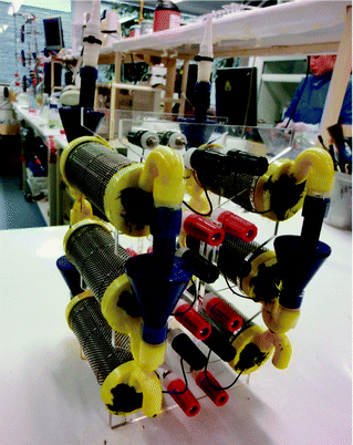 | ||
| Fig. 1 Two cascades of 3 MFCs each, assembled with air-gap adaptors. | ||
Twelve cylindrical MFCs were arranged in cascades of three units, with the four cascades forming the stack. MFCs within the cascades were connected electrically in parallel, and the four parallel-connected triplets were subsequently connected in series. Custom-made air-gap adaptors that also served as lids for the cylinders, with 8 mm internal diameter, were 3D printed in ABS material (FDM Titan, Laserlines, UK), and were used to facilitate the flow of feedstock in a sequential manner. The ABS lids were sealed in place using a biocompatible sealant (“Wet Water Sticky Stuff”, Barry Read Supplies, Devon, UK). Fig. 1 shows the assembly of two (of a total of four) ceramic MFC cascades, with a PMMA frame, that was laser-cut in-house.
Small-scale (6.25 mL) EcoBot MFCs
These MFCs were prepared as described previously,11 with the only difference being that the open-to-air cathodes were replaced with the same MPL material as described above. The substratum used for the MPL coating was plain carbon cloth (Fuel Cell Earth LLC, Stoneham, MA). The small Nanocure® MFCs are currently being employed as the stack for powering the fourth robot in the series of EcoBots, and, due to their level of maturity and length of operation (4 years), were disconnected from the EcoBot platform and utilised as the control stack, fed with urine for running the mobile phone. Fig. 2 shows the working EcoBot-IV platform with the 24 MFCs and the inset shows a close-up of a single unit.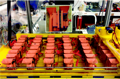 | ||
| Fig. 2 MFC stack consisting of 24 small (6.25 mL) units, as assembled for running EcoBot-IV. The yellow motorised gantry system shown on the right is part of the automatic feeding mechanism for uniform MFC maintenance. The inset shows a close-up of a single Nanocure® MFC, with the open to air cathode shown on the right hand side. The small red screw provides pressure control for better electrode-to-membrane contact. | ||
The 24 MFCs were connected in groups of 2 units in parallel, and the 12 groups formed, connected in series (2 × 12 stack). This resulted in a robust configuration with no cell polarity reversal, and sufficient elements in series to produce a relatively high collective voltage of 7.2 V (open circuit).
Inoculum, preparation and running conditions
Both types of MFC were inoculated from anaerobic sludge, provided by the Wessex Water Scientific Laboratory (Cam Valley, Saltford, UK), which was supplemented with acetate (as the source of carbon energy) and yeast-extract (as the source of minerals/nutrients). The acetate–yeast extract was added into 1 L of anaerobic sludge and consisted of 25 mM sodium acetate (Fisher Scientific, UK) and 0.1% w/v yeast extract (Oxoid, UK) with no added buffers and a pH of 6.7.Initially and for approximately 1 week, the ceramic MFCs were maintained under batch mode conditions, after which they were switched to continuous flow, using a Watson Marlow 205U peristaltic pump (Watson Marlow, UK). The flow rate used was 250 μL min−1 (hydraulic retention time – HRT = 3 hours, 48 minutes) and the same flow rate was subsequently employed for urine. The EcoBot MFCs were also maintained in fed-batch mode with 3 mL of either acetate–yeast extract or urine fed twice a day, resulting in an HRT ≈ 24 hours.
Urine was collected from healthy individuals with no known previous medical conditions, and pooled together before directly adding it to the MFCs. The pH of urine was between 6.4 and 6.7, the mean COD value was 12.5 g L−1, and the conductivity ranged between 36 and 40 mS cm−1. Urine was added as the fuel always on the day of collection.
Polarisation runs, data collection and power calculations
Polarisation experiments were performed using the Resistorstat tool,12 after allowing at least 30 min under open-circuit conditions, so as to establish quasi steady-state values. The time constant for each resistance was 5 min, in the range of 40 kΩ to 4 Ω, and the total number of resistances employed was 34. Data were logged using a multi-channel Agilent 34972A, LXI Data Acquisition/Switch Unit (Farnell, UK) and were then processed using the Microsoft Excel and GraphPad Prism software packages. Current and power were calculated as previously described.3Mobile phone battery charging and energy harvesting
It has already been demonstrated that the miniaturisation and multiplication approach is a viable route for scaling up power output levels.11,13–17 In order to further emphasise the viability of MFCs in the context of energy availability in remote locations, especially when the fuel is urine, it was deemed necessary to investigate whether the scaled-up energy from MFC stacks could be utilised for re-charging and running a mobile phone: (i) via a state-of-the-art energy harvester, such as the Texas Instruments BQ25504EVM-674 (Farnell, UK), (ii) using a smaller battery, (iii) using the larger battery that comes with the phone off-the-shelf and (iv) charging the phone with the smaller battery directly (i.e. no energy-harvester). The smaller battery used was an Overlander lithium polymer cell, 3.7 V, 150 mA h (Farnell, UK). The larger battery was a Samsung lithium-ion cell, 3.7 V, 1000 mA h, which came with the actual mobile phone. The cold-start voltage of the TI energy harvester device is 0.33 V and at the current levels produced by MFCs, it can operate at an efficiency of 90%.The mobile phone selected was the Samsung GT-E2121B as a handset that will perform all the basic functions of a mobile phone, in addition to Bluetooth® connectivity, music playback and internet browsing. The output voltage from the 12-in-series/2-in-parallel EcoBot stack was in principle sufficient to attempt re-charging the battery directly, however the voltage output from the 4-in-series/3-in-parallel ceramic MFC stack was theoretically lower than the input requirements of the batteries, and thus the TI energy harvester was used in the latter case.
Results and discussion
Ceramic MFC stack with an energy harvesting board
Fig. 3 shows the power and polarisation curves of the ceramic MFC stack of twelve units, when fed with acetate–yeast extract or urine. As can be seen, there was a 4-fold improvement in the MFC stack power performance, as a result of feeding with neat urine.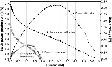 | ||
| Fig. 3 Power and polarisation curves from the ceramic 12× MFC stack, when fed with acetate–tryptone extract (open symbols) and urine (closed symbols). | ||
Fig. 4 shows the power behaviour of the ceramic MFC stack as it is charging the Samsung mobile phone with the smaller battery, performing normal operational functions. The cut-off voltage i.e. where the phone turns OFF is 3.25 V, and the target charge voltage is 3.7 V. As can be seen, the MFC stack power remains relatively stable and the rate of charge is approximately 30 hours. Fig. 5 shows the mobile phone switched ON and running next to the ceramic MFC stack.
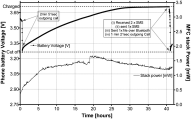 | ||
| Fig. 4 MFC stack power behaviour during the charging and operation of the Samsung GT-E2121B mobile phone. During the operation, 2 outgoing calls were made, 2 text messages were received and 1 was sent, and Bluetooth® was enabled for synchronising with another handset for file transfer. | ||
 | ||
| Fig. 5 Samsung GT-E2121B powered by the ceramic MFC stack. | ||
Small-scale (6.25 mL) EcoBot MFCs
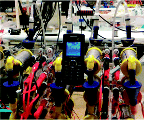
These MFCs and their power characteristics have been previously reported in the literature.11,15 The power output from the stack, when connected onto the EcoBot platform, ranges approximately between 2 and 2.5 mW. When the MFCs were disconnected from the EcoBot platform, which is maintaining the stack, the power output decreased to 1–1.5 mW, due to the change in the electrical configuration (from 8-in-series/3-in-parallel to 12-in-series/2-in-parallel). This was necessary in order to achieve a higher voltage for re-charging the battery directly.Even under this lower power output configuration, the 24-MFC stack was capable of charging the Samsung mobile phone directly, as shown in Fig. 6. The mobile phone handset was charged to the target 3.7 V threshold and the energy stored in the phone's battery was sufficient to support a 4 minute and 20 second outgoing call, after which the phone stopped working (cut-off reached). The re-charging from 3.2 V to 3.7 V took just over 12 hours.
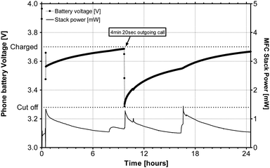 | ||
| Fig. 6 MFC stack (24 × 6.25 mL units) powering the Samsung mobile phone, when fed with neat urine. | ||
Fig. 7 shows a snapshot from the video recording of one of the voice calls performed by the MFC powered Samsung mobile phone handset.
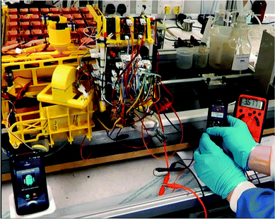 | ||
| Fig. 7 Snapshot of the outgoing voice call made by the MFC powered Samsung E2121 (right) to the receiving HTC mobile handset (left); the digital multi-metre on the far right shows the battery voltage. | ||
The stacking of multiple small-scale MFCs, has previously been shown as a viable approach to scale-up for practical applications.4 This is also verified in the current study from the small-scale EcoBot-IV MFCs, and also from the new ceramic MFC stacks, which have successfully charged the Samsung larger battery (1000 mA h) as shown in Fig. 8. A 24 hour charge was sufficient to power the phone for 25 minutes, during which several SMS messages were received and sent, and also a 6 minute 20 second outgoing call was made. Small rather than large scale volumes would intuitively be expected to be more powerful, since the ratio of the active surface area (square law) serving a given volume (cube law) is more favourable at the smaller scale.
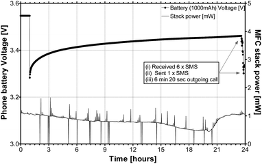 | ||
| Fig. 8 MFC stack power during the charging and operation of mobile phone, when using the larger Samsung 1000 mA h battery. During the operation, 1 outgoing call was made, 6 text messages were received and 1 was sent. | ||
In MFCs, efficient power generation is inherently linked to fast microbial metabolic rates, thus implying more efficient utilisation and transformation – i.e. treatment – of the substrate. Organic components are utilised by the microbes and the majority of organic carbon is oxidised – via electron transfer – to CO2, whilst a small proportion is used as building-blocks for new daughter cell material. A proportion of inorganic N, P and K is also used as a component of new daughter cells, and therefore removed from the waste-stream, although the majority may be lost by other means such as mineralisation (i.e. struvite production). An additional pathway for N would be conversion to NH3, depending on pH in particular.
Assuming that optimised power output levels and waste utilisation rates are realised with small-scale MFCs for large-scale stacks, the financial aspects become critical for practical implementation and commercialisation; these would involve material, capital and running costs. For the latter two, capital investment would be equivalent to any other new venture in green technology however the costs of service and maintenance would be far lower due to the inherent longevity and stability properties of the MFC technology. In the case of the former, the ceramic materials approach offers unparalleled advantages in terms of cost, integrity and reliability. For example, the cost of each 49 mL off-the-shelf clay cylinder, which may have a lifetime of decades, was £0.32p, with the total cost of one complete MFC unit, including the electrodes and current collectors, being ∼£1. This shows that the technology has the potential for economic viability.
The current study has demonstrably shown the feasibility of utilising a natural and abundant human by-product, directly into useful electricity, by powering a commercially available mobile phone. In the context of remote communities in countries of the Developing World, or even in any remote location without access to conventional electricity supply, this would be a valuable and timely breakthrough.
Conclusions
This is the world's first demonstration that mobile phone batteries can be directly charged – previously considered impossible – by a stack of MFCs feeding on urine. Compared to other commonplace organic feedstocks, urine is shown to be a superior fuel for direct electricity generation. This opens up numerous possibilities for waste utilisation in remote locations and accessible levels of useful energy.Acknowledgements
This project has been funded by the UK Engineering and Physical Sciences Research Council (EPSRC) Career Acceleration Programme, grant no. EP/I004653/1, the Bill & Melinda Gates Foundation, grant no. OPP1044458 as well as the UK Technology Strategy Board through the “Greenius” award. P. Ledezma is a scholar of the National Science and Technology Council of Mexico (CONACyT) Ref. 206298.Notes and references
- M. C. Potter, Proc. R. Soc. London, Ser. B, 1911, 84, 260 CrossRef.
- R. M. Allen and H. P. Bennetto, Appl. Biochem. Biotechnol., 1993, 39/40, 27 CrossRef.
- I. Ieropoulos, J. Greenman and C. Melhuish, Int. J. Energy Res., 2008, 32, 1228 CrossRef CAS.
- I. Ieropoulos, J. Greenman and C. Melhuish, Bioelectrochemistry, 2010, 78, 44 CrossRef CAS.
- I. Ieropoulos, J. Greenman and C. Melhuish, Phys. Chem. Chem. Phys., 2012, 14, 94 RSC.
- P. Kuntke, K. M. Smiech, H. Bruning, G. Zeeman, M. Saakes and T. H. J. A. Sleutels, et al. , Water Res., 2012, 46, 2627 CrossRef CAS.
- B. K. Boggs, R. L. King and G. G. Botte, Chem. Commun., 2009, 4859 RSC.
- A. Hug and K. M. Udert, Water Res., 2013, 47, 289 CrossRef CAS.
- F. Zhang, G. Zheng, J. Grimaud, J. Hurst and Z. He, Bioresour. Technol., 2013, 134, 251 CrossRef CAS.
- C. Santoro, Y. Lei, B. Li and P. Cristiani, Biochem. Eng. J., 2012, 62, 8 CrossRef CAS.
- I. Ieropoulos, J. Greenman, C. Melhuish and I. Horsfield, Proceedings of the 12th International Conference on the Synthesis and Simulation of Living Systems, Odense, 2010.
- N. Degrenne, F. Buret, B. Allard and P. Bevilacqua, J. Power Sources, 2012, 205, 188 CrossRef CAS.
- I. Ieropoulos, C. Melhuish and J. Greenman, Proceedings of the 7th European Conference in Artificial Life, Dortmund, 2003.
- C. Melhuish, I. Ieropoulos, J. Greenman and I. Horsfield, Auton. Robot, 2006, 21, 187 CrossRef.
- G. Papaharalabos, J. Greenman, C. Melhuish, C. Santoro, P. Cristiani and B. Li, et al. , Int. J. Hydrogen Energy, 2013 DOI:10.1016/j.ijhydene.2013.05.138.
- I. Ieropoulos, J. Greenman, D. Lewis and O. Knoop, JWaSHDev, 2013 DOI:10.2166/washdev.2013.117.
- P. Ledezma, A. Stinchcombe, J. Greenman and I. Ieropoulos, Phys. Chem. Chem. Phys., 2013, 15, 2278 RSC.
| This journal is © the Owner Societies 2013 |
