 Open Access Article
Creative Commons Attribution 3.0 Unported Licence
Protein film photoelectrochemistry of the water oxidation enzyme photosystem II
Masaru
Kato†
,
Jenny Z.
Zhang
,
Nicholas
Paul
and
Erwin
Reisner
*
Department of Chemistry, University of Cambridge, Lensfield Road, Cambridge CB2 1EW, UK. E-mail: reisner@ch.cam.ac.uk
First published on 26th March 2014
Abstract
Photosynthesis is responsible for the sunlight-powered conversion of carbon dioxide and water into chemical energy in the form of carbohydrates and the release of O2 as a by-product. Although many proteins are involved in photosynthesis, the fascinating machinery of Photosystem II (PSII) is at the heart of this process. This tutorial review describes an emerging technique named protein film photoelectrochemistry (PF-PEC), which allows for the light-dependent activity of PSII adsorbed onto an electrode surface to be studied. The technique is straightforward to use, does not require highly specialised and/or expensive equipment, is highly selective for the active fractions of the adsorbed enzyme, and requires a small amount of enzyme sample. The use of PF-PEC to study PSII can yield insights into its activity, stability, quantum yields, redox behaviour, and interfacial electron transfer pathways. It can also be used in PSII inhibition studies and chemical screening, which may prove useful in the development of biosensors. PSII PF-PEC cells also serve as proof-of-principle solar water oxidation systems; here, a comparison is made against PSII-inspired synthetic photocatalysts and materials for artificial photosynthesis.
Key learning points(1) Key functionalities and basic photophysics of PSII.(2) Methodology of protein film photoelectrochemistry and its application to PSII. (3) Strategies for integration of PSII into electrodes. (4) Applications of PSII protein film photoelectrochemistry. (5) Bio-inspired photoelectrochemical water oxidation catalysts and materials. |
1. Introduction
1.1 Overview and motivation
Natural photosynthesis is the process by which light energy converts water and CO2 into O2 and carbohydrates; a chemical and thereby storable form of energy for use by oxygenic photosynthetic organisms. Photosystem II (PSII) is the first enzyme in the photosynthetic chain and responsible for the efficient extraction of electrons from water, evolution of O2, and contribution to the proton gradient that drives ATP synthesis.1,2The study of PSII function is important for several reasons. PSII is the benchmark photocatalyst for solar water oxidation, and serves as a guide to the design of artificial photosynthetic systems for solar fuel production.3 Moreover, the activity of PSII impacts heavily on crop production. Since there is a growing global concern over food security and the availability of agricultural land for biofuel production, understanding how PSII activity can be affected by certain chemical and environmental factors may lead to quicker solutions and innovations. Having access to straightforward characterisation and screening techniques, such as protein film photoelectrochemistry (PF-PEC), may greatly drive progress in these areas.4–6
1.2 Global protein structure and key functions of PSII
PSII is a transmembrane protein that resides in the thylakoid membrane of plants, algae and cyanobacteria (Fig. 1). It falls under the category of reaction centre (RC) proteins, in which charge generation is the primary function. Protein crystallographic techniques have revealed PSII to be a dimeric complex, with both monomers exhibiting virtually the same structural composition.1,7 The monomers are related by a pseudo two-fold axis of rotation perpendicular to the plane of the membrane (Fig. 1B). The PSII dimer has global dimensions of approximately 20.5 × 10.5 × 11.0 nm3 and a mass of ∼700 kDa.7 Each monomer comprises of 20 protein subunits and 35 chlorophylls (Chlorophyll a, Chl a), 11 carotenoids (β-carotene, β-Car), two pheophytins (Phe), two plastoquinones (QA and QB), two heme irons, one non-heme iron and a manganese-calcium (Mn4Ca) cluster, also known as the oxygen evolving complex (OEC) or the water oxidising complex.1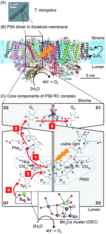 | ||
| Fig. 1 (A) Optical micrograph of the thermophilic cyanobacterium Thermosynechococcus elongatus (T. elongatus).8 (B) Schematic representation of the PSII dimer (Protein Data Bank ID: 3ARC)1 embedded in the thylakoid membrane. Water oxidation at the OEC results in the liberation of H+ and O2 coupled to the reduction of the terminal quinone, QB, in the QB pocket to release the reduced H2QB. (C) Simplified schematic representation of the RC complex with the D1 (PsbA), D2 (PsbD) subunits and core components involved in photosynthetic electron transfer. Red arrows indicate the direction of electron transfer. Step 1: charge separation occurs by direct photo-excitation or by energy transfer from the neighbouring antenna proteins CP47 (PsbB) and CP43 (PsbC), which flank D1 and D2, to form [P680+–PheD1−]. Step 2: electron transfer from PheD1− to QA. Step 3: Tyrz donates an electron to fill the hole of P680+. Step 4: the hole migrates from Tyrz+ to the Mn4Ca cluster. Step 5: electron transfer from QA− to the terminal acceptor QB. Charge separation and recombination lifetimes are summarised in Fig. 3. | ||
PSII contains two primary structural units with specific functions. The first consists of the antenna CP43 and CP47 subunits, which are responsible for light absorption and energy transfer. The other is the RC complex, which is made up of the D1 and D2 subunits. The RC complex is able to absorb light energy on its own, but also receives energy from the antenna subunits to generate charges (Fig. 1C). The remaining subunits that make up PSII are distributed amongst and around these four subunits; their potential functions are discussed elsewhere.2
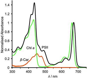
The asymmetric, cyclic π-electronic configuration of chlorophyll opens up a number of optically allowed electronic transitions. The transitions with the largest absorption cross-section are centred at 675 nm (1.84 eV) and 420–440 nm (2.95–2.82 eV), respectively. Upon white light irradiation, the PSII P680 chromophore can either be excited and form an exciton (electron–hole pair) directly or receive energy from the antenna subunits. Water oxidation can function under extremely low light conditions, due in part to energy transfer from the antenna to the RC complex. High energy photons (∼350–510 nm, Fig. 2) can also be harvested, directly in the RC or by antenna energy transfer, but with significant energy loss as water oxidation requires ∼1.8 eV (675 nm) to operate. PSII suffers from constant photodegradation and an increased light intensity scales with a reduction of PSII lifetime. This is partly due to saturated RCs, which can generate Chl a triplet states that can react with triplet O2 to give highly reactive singlet O2 species. The generation of singlet O2 is a known cause of increased protein degradation.9
Water photolysis involves the splitting of two water molecules to give four protons, four electrons and one molecule of O2. Consequently, the process requires four photo-excitations to be split (sequentially) into charge separated states and the accumulation of four holes on the OEC. PSII has been reported to carry out this reaction at turnover frequencies (TOF) of up to 1000 s−1in vivo.11
The generated electron and hole are transferred in opposite directions across PSII.9 A full scheme of charge separation from one photoexcitation within the PSII RC is given in Fig. 1C, and the charge separation lifetimes are given in Fig. 3. Electrons are transferred from P680* to PheD1, then to the primary plastoquinone, QA, and finally to the secondary plastoquinone, QB, which upon 2-electron/2-proton reduction becomes a hydroquinone (H2QB) and labile within the QB pocket. The labile H2QB then diffuses out into the thylakoid membrane and reduces the cytochrome b6f complex. The vacant QB pocket is then free to receive another QB molecule from the plastoquinone ‘pool’ within the thylakoid membrane. There is structural data to suggest the presence of a third plastoquinone commonly dubbed as “QC”, which resides in a second channel adjacent to the QB site.13
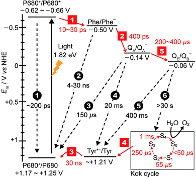 | ||
| Fig. 3 Redox potentials of cofactors15,16 along with charge separation (red squares) and charge recombination (black circles) pathways and rates.12,17,18 Note that step 1 is the lifetime of the initial exciton/charge-transfer states. The arrows indicate the direction of electron transfer. The insert on the bottom right displays the time constants for the formation of each photo-induced oxidation of the Mn4Ca cluster in the Kok cycle (S0–S4 states). | ||
The holes migrate towards the OEC, where water oxidation occurs after accumulation of four holes in the Kok cycle (Fig. 3). With each subsequent charge separation, the oxidation of the OEC becomes slower. It is believed that the 1 ms step to form the O2-releasing S4 state in the OEC is the rate-limiting step in the Kok cycle. At the terminal electron acceptor site, it takes up to 400 μs to form QB− to give the [OEC(S1)+–QB−] charge separated state, and the second reduction of QB− to QB2− takes at least 800 μs. The overall rate of electron transfer from PSII to the neighbouring cytochrome b6f protein is limited by the hydroquinone diffusion, which takes approximately 10 ms.14
One of the amazing aspects of PSII photophysics is its robustness against fast charge recombination. For [P680+–PheD1−], charge recombination occurs at a timescale on the order of 4–30 ns, which is 2–3 orders of magnitude slower than the separation, and 1–2 orders slower than subsequent charge separation to QA.9 Efficiency only increases as the charges move further apart and spatial separation increases, for example charge recombination between P680+ and QA− is ∼150 μs. At the maximal displacement, with the electron on the QB site and the hole on the Mn4Ca cluster, recombination timescales are >30 s, which is at least 3 orders of magnitude slower than the rate limiting step of water photolysis. Whilst the mechanism of charge separation is highly efficient in terms of low levels of charge recombination, there is a significant energy penalty paid due to the number of charge transfer steps associated with it. Fig. 3 shows the redox levels of cofactors,15,16 and charge separation and recombination rates.12,17,18
2. Protein film photoelectrochemistry (PF-PEC)
2.1 Why use PF-PEC to study PSII?
The most common method for probing the activity of isolated PSII is through O2 evolution measurements using a Clark-type electrode.19 Since a natural plastoquinone pool is not available in these circumstances, alternative electron acceptors must be added to extract electrons from the terminal reduced site of PSII during O2 evolution measurements. To some extent, the O2 evolution rates will be dependent on the concentration of the electron mediator, its redox potential, diffusion kinetics, and affinity towards the reduced site of PSII.An alternative method for the characterisation of O2 evolution activity and charge separation efficiency in PSII is the use of chlorophyll fluorescence techniques.20 When the RC is swamped with charges (a closed RC), charge transfer efficiency is lowered, and the chlorophyll singlets live longer giving rise to an increase in fluorescence yield. Likewise, when charges are extracted efficiently (an open RC), the opposite is observed. The main advantages of this method are that fluorescence is easy to track over any timescale, it is molecule specific and the data is relatively easy to interpret. The disadvantages are that it is an indirect measurement of charges within the RC and the data can be highly dependent on the experimental parameters used such as light intensity, excitation wavelength and sample state (solid film or dispersed in solution). It also suffers from the possibility of data contamination from the presence of spectroscopically active yet chemically inactive proteins, which may result in false spectroscopic readings.
The electrocatalytic properties of metalloenzymes such as hydrogenases under different conditions have been previously studied in detail by protein film electrochemistry.21 PF-PEC allows the study of enzymes through photoelectrochemical techniques. It involves the integration of the photo/redox active enzyme of interest onto the working electrode of an electrochemical cell so that photo-induced electrochemical events can be measured on the surface of the electrode. In the case of PSII, for example, PF-PEC can be used to probe the stability of the isolated enzyme, interfacial electron injection efficiencies and O2 evolution rates under different applied potentials. In conjunction with redox mediators, it allows the potential-dependent direct and mediated electron transfer from PSII to the electrode to be measured.
Another advantage of PF-PEC is that it is a highly sensitive technique, which only responds to the active protein and is blind to inactive or denatured fractions of immobilised protein. Furthermore, it requires a small amount of enzyme to yield good quality electrochemical data: only sub-picomol amounts of PSII are needed for PF-PEC, whereas Clark-type electrode measurements require several orders of magnitude more PSII.19
2.2 Setup of PSII PF-PEC cells
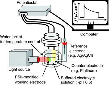
A typical three-electrode system for PSII PF-PEC is shown in Fig. 4. Since PEC events are measured on the surface of the working electrode, the working electrode material (Section 2.3) and PSII integration strategy (Section 2.8) must be carefully considered. A bias potential is applied between the working electrode and the reference electrode and the current that passes between the working and the counter electrodes is recorded by a potentiostat. A saturated calomel electrode or Ag/AgCl electrode can be used as a reference electrode and a platinum wire is commonly used as a counter electrode. An external O2 detection sensor can also be placed next to the working electrode in the cell. The light source used should include wavelengths of around 680 nm at moderate intensities (∼1–50 mW cm−2), which is sufficient to initiate a reasonable level of protein photo-response whilst minimising energy loss during energy transfer and light-induced protein degradation (Section 1.2.1). The electrolyte solution used in PSII PF-PEC must be buffered near neutral pH, usually using 2-(N-morpholino)ethanesulfonic acid (MES) buffer. An appropriate surfactant (such as n-dodecyl-β-D-maltoside) may also be employed to maintain the catalytic activity of PSII during electrochemical measurements.22,23 The cell can be connected to a water circulator to regulate its temperature during experiments.2.3 Selection of working electrode material
The electrode material for PF-PEC studies must be carefully chosen to allow for the immobilisation of PSII in an active configuration and to match the redox levels of the terminal plastoquinones in PSII. Various electrode materials have been used in PF-PEC with gold being the most common. Gold has a high electrical conductivity and a smooth, hydrophobic surface. Surface functionalisation of gold is necessary for immobilisation of PSII and thiol groups are commonly used as anchoring groups to achieve self-assembled monolayers (SAMs; Section 2.8).22–25Metal oxides are gaining popularity as PF-PEC electrode materials as they have several advantages over gold. For example, the surface of metal oxides is generally hydrophilic, it can be easily modified into nanostructured surface morphologies for higher enzyme loading and it is less expensive than noble metal electrodes.26–28 PSII can even be directly immobilised on the metal oxide surface or entrapped in the nanopores of nanostructures without any surface functionalisation (Section 2.8).27 Transparent, n-doped and highly conductive metal oxides such as indium tin oxide (ITO) are particularly suitable for PF-PEC studies.27,28 Most other metal oxides are semiconductors and the conduction band of the material must therefore be carefully matched to the redox potentials of cofactors within the enzyme to allow for interfacial electron transfer.
Carbon materials such as glassy carbon or pyrolytic graphite edge (PGE) electrodes have also been employed and the redox potentials of cofactors within PSII were previously reported using a PGE electrode.29 However, these potentials have since been re-determined using optically transparent thin-layer electrodes.15
2.4 Selection of PSII for PF-PEC
Currently, no major structural differences in PSII are known amongst different photosynthetic organisms.2 However, PSII isolated from thermophilic cyanobacteria generally exhibit a higher degree of robustness compared to those isolated from other organisms such as spinach. As such, PSII isolated from Thermosynechococcus elongatus,30Thermosynechococcus vulcanus,24 and Mastigocladus laminosus25 are commonly employed in PF-PEC studies.PSII cannot currently be purchased through commercial sources, but can be isolated from cyanobacterial cells by standard enzyme purification techniques, which involves cellular lysis and differential centrifugation to isolate thylakoid membranes. The thylakoid membranes obtained can then be solubilised with detergents to isolate the transmembrane PSII. Genetically modified PSII containing a histidine tag (His-tag) can be separated using a nickel-nitrilotriacetic acid (Ni-NTA) column;30 wild-type PSII can be isolated using ion exchange chromatography.
Isolated PSII lacks the plastoquinone pool and the D1 protein repair machinery available in vivo, which replaces the photo-damaged D1 protein in photosynthetic organisms with a new copy every five hours under low light conditions, and every 20 minutes under intense illumination.31 Therefore, isolated PSII is very light sensitive and must be handled in the dark (or under weak green light) to avoid light damage, and preferably over ice, prior to experiments. PSII is typically stored in a MES buffer solution containing high concentrations of glycol and betaine, below −80 °C before use.
O2 evolution rates of isolated PSII are typically determined in an aqueous, buffered solution that contains an electron acceptor (Section 2.1). The highest O2 evolution rate obtained from PSII isolated from T. elongatus was ∼6000 μmol O2 (mg Chl a)−1 h−1,19 which is equal to ∼50 mol O2 (mol PSII monomer)−1 s−1.
2.5 Direct (DET) and mediated electron transfer (MET)
Photocurrent responses may be observed both in the absence and presence of diffusional electron mediators in the electrolyte solution. DET occurs in the absence of electron mediators and may be observed when PSII is integrated onto a bare electrode surface.27 DET is sensitive to the distance between reducing sites in PSII and the electrode surface.28 The photocurrents observed from DET studies can give insights into the degree of electronic coupling between immobilised PSII and the electrode surface, and the population of PSII that is immobilised in the correct orientation for direct electron injection. Since QA and QB are known electron donation sites of PSII to the electrode and located on the stromal side of the enzyme (Fig. 1),27 it is only possible to observe DET when the stromal side is in direct contact with the electrode surface.MET occurs when electron mediators are present in the electrolyte solution or are integrated on the electrode surface. Appropriate electron mediators are redox active molecules with a redox potential that lies between the redox potential of the terminal quinones and the applied potential of the electrode. The most common soluble electron acceptor employed for PSII is 2,6-dichloro-1,4-benzoquinone (DCBQ, Em = +21 mV vs. NHE).27 Os-based redox polymers have also been employed to mediate electron transfer on gold electrodes (Section 2.8.3). The photocurrent responses from MET are significantly enhanced compared to those from DET in PSII PF-PEC systems as electron mediators can, in principle, receive electrons from almost all active PSII immobilised on the electrode independent of the orientation of PSII. MET with a soluble mediator is controlled by diffusional mass transport; a slow kinetic process and likely rate determining in PSII PF-PEC.
2.6 Analysis of PSII PF-PEC results
Upon irradiation, the PSII-integrated electrode will produce a photocurrent response corresponding to PSII electron injection into the electrode with concomitant water oxidation to O2. An illustrative example of a photocurrent response plot obtained using PSII PF-PEC is presented in Fig. 5A, where the PEC response in the presence and absence of PSII is shown.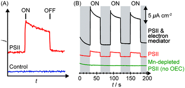 | ||
| Fig. 5 (A) Illustration of photocurrent response in a PF-PEC cell in the presence (red) and absence (blue) of PSII. ON indicates the start of irradiation, OFF indicates the end of irradiation. (B) Typical chronoamperograms obtained by PSII in the absence of any chemical manipulation (red), presence of an electron mediator (black), and absence of the OEC (green).27 | ||
The photocurrents are normalised against the geometrical surface area of the electrode to give the photocurrent density (j/μA cm−2), as shown in Fig. 5B. There are two definitions of surface areas: the effective surface area (the real 3D area available for adsorption) and the geometrical surface area (the macroscopically measured 2D surface area). The geometrical surface area is only equal to the real surface area when the electrode surface is atomically flat. A theoretical density of a monolayer of PSII on a flat surface was calculated to be 0.74 pmol cm−2, and a theoretical photocurrent density of the monolayer to be 43 μA cm−2.32 Generally, observed photocurrent densities in PSII PF-PEC are reported in photocurrent per geometrical surface area. In principle, increasing the ratio of the effective to the geometrical surface area increases the PSII loading and photocurrent densities.
The photocurrent densities generated by PSII-electrodes can be used to estimate TOFs of the PSII, if the number of PSII immobilised on the electrode is known, and assuming 100% Faraday efficiency with four electrons being transferred per O2 released. The amount of PSII can be quantified based on the intensity of UV-vis absorption of Chl a (λmax ∼ 665 nm, Fig. 2) extracted from PSII using organic solvents such as methanol (ε = 79.95 (mg Chl a)−1 mL cm−1).27 It should be noted that the first and second photo-response spikes may be affected by charging effects, which give rise to higher initial currents that decay rapidly. As such, the third or fourth photocurrent peaks should be used in TOF calculations. The incident photon-to-current conversion efficiencies (IPCEs) for PSII-photoanodes can be determined if the photon flux and the wavelength of a monochromatic light source are known. IPCEs of PSII electrodes are calculated using the following equation:26
![[thin space (1/6-em)]](https://www.rsc.org/images/entities/char_2009.gif) 484 A s mol−1), P is the irradiance (W m−2), λ is the wavelength of light (nm), NA is the Avogadro number (6.022 × 10²³ mol−1), h is Planck constant (6.626 × 10⁻³⁴ J s) and c is the speed of light (2.998 × 10⁸ m s−1).
484 A s mol−1), P is the irradiance (W m−2), λ is the wavelength of light (nm), NA is the Avogadro number (6.022 × 10²³ mol−1), h is Planck constant (6.626 × 10⁻³⁴ J s) and c is the speed of light (2.998 × 10⁸ m s−1).
2.7 Validation and control experiments
Several control experiments should be performed to clarify the source of the photo-response recorded. Before the start of an experiment, a photocurrent should be run on the enzyme-free working electrode to establish the background and also verify that the material itself does not behave as a photoanode.Following a PSII PF-PEC experiment, a mediator such as DCBQ can be added to the cell. Assuming that PSII is not quantitatively immobilised in a photoactive configuration on the electrode, the addition of the mediator should cause an increase in photocurrent (Fig. 5B). As such, an indication of whether PSII is deposited as mono or multi-layers, and/or with poor orientation, can be obtained.
Mn-depleted PSII, obtained by treatment with tris(hydroxymethyl)aminomethane or NH2OH,30 can be used in the PF-PEC studies to verify that the photocurrent stems from water oxidation. A fully Mn-depleted PSII contains no catalyst and ideally no photocurrent should be observable (Fig. 5B).27,28 In addition, PF-PEC studies of PSII should in principle be performed with simultaneous O2 detection, but quantification of O2 is often hampered by the low amount of PSII used and O2 generated in PF-PEC studies.
2.8 Immobilisation of PSII onto electrodes
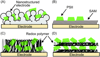
Enzymes can be immobilised onto electrodes using several strategies. Fig. 6 summarises four main methods for adsorbing PSII,4–6 which will be discussed in more detail here. A summary of their experimental conditions and respective outcomes is presented in Table 1.| Entry | Electrode | PSII source | j (μA cm−2) | Bias voltage (V vs. NHE) | pH | Light source | PSII (pmol cm−2) | TOF (s−1) | Stability (min) | TON | IPCE (%) | Ref. | |
|---|---|---|---|---|---|---|---|---|---|---|---|---|---|
| DET | MET | ||||||||||||
| a TON calculated considering the best known in vitro O2-evolution rates of 6000 μmol O2 (mg Chl a)−1 h−1 and a life time of 30 min. b Mediated electron transfer using 1,4-napthoquinone-2-sulphonate. c Mediated electron transfer using DCBQ. d Converted from Ag/AgCl to NHE by the addition of 0.20 V. e Light intensity converted from 3.3 mW/0.16 cm2. f PSII-enriched membrane particles. g Converted from SCE to NHE by the addition of 0.24 V. h Reported absorbed light power. i Open circuit potential and converted from Ag/AgCl to NHE by the addition of 0.20 V. j TON per dye molecule. k Calculated for total water splitting considering measured H2 and O2 gas. l Converted from a reversible hydrogen electrode to NHE by adding −0.0592 × 9.2 = −0.545 V. | |||||||||||||
| PSII in vivo | |||||||||||||
| T. elongatus | ≤103 | ≤106![[thin space (1/6-em)]](https://www.rsc.org/images/entities/char_2009.gif) a a |
11 and 19 | ||||||||||
| PSII incorporated into SAM-free nanoporous electrodes | |||||||||||||
| 1 | mesoITO|PSII | T. elongatus | 1.6 | 0.50 | 6.5 | 635 nm, 8 mW cm−2 | 76 | 0.18 | t 1/2 < 5 | 27 | |||
| 12b | 1.4b | 0.3b | |||||||||||
| 22c | 3.2c | ||||||||||||
| PSII immobilised on SAM-modified electrodes | |||||||||||||
| 2 | mesoITO|C2CO2−|PSII (electrostatic) | T. elongatus | 0.50 | 6.5 | 679 nm, 10 mW cm−2 | 1.6 | 0.33 | t 1/2 < 5 | 0.005 | 28 | |||
| 0.28 | 1.4c | 1.4c | 0.03c | ||||||||||
| 3 | mesoITO|C2CO2−|PSII (covalent) | T. elongatus | 0.50 | 6.5 | 679 nm, 10 mW cm−2 | 2.0 | 0.61 | t 1/2 ∼ 12 | 0.01 | 28 | |||
| 0.43 | 4.5c | 4.6c | 0.10c | ||||||||||
| 4 | Au|Ni-NTA|PSII | T. elongatus | 14c | 0.50d | 6.5 | 675 nm, ∼1.76 mW cm−2 | 0.29 | t 1/2 = 18 | 22 | ||||
| 5 | Au|Ni-NTA|PSII | T. vulcanus | 0.13 | 0.40d | 6.4 | 680 nm, 21 mW cm−2![[thin space (1/6-em)]](https://www.rsc.org/images/entities/char_2009.gif) e e |
24 | ||||||
| 6 | Au|Ni-NTA|PSII (nanoparticles) | T. vulcanus | 2.4 | 0.40d | 6.4 | 680 nm, 21 mW cm−2![[thin space (1/6-em)]](https://www.rsc.org/images/entities/char_2009.gif) e e |
24 | ||||||
| 7 | TiO2|Ru-dye|PSII | Spinachf | 35c | 0.04g | 5.5–6.0 | >420 nm, 35 mW cm−2 | 12 | 26 | |||||
| PSII entrapped in redox polymers on electrodes | |||||||||||||
| 8 | Au|Os redox polymer|PSII | T. elongatus | 45 | 0.50 | 6.5 | 675 nm, 2.65 mW cm−2 | t 0.85 ∼ 55 | 23 | |||||
| 9 | Au|pMBQ|PSII | M. laminosus | ∼2.7 | 0.39g | 7.4 | >400 nm, 0.1 Wh | 0.9 | 25 | |||||
| PSII integrated in layer-by-layer assemblies of redox polymers on electrodes | |||||||||||||
| 10 | PBV2+|PSII|PBV2+|PSII | M. laminosus | 0.50 | 0.20d | 7.2 | 675 nm, 0.28 mW cm−2 | 3.8–5.2 | ∼0.3 | 33 | ||||
| Synthetic water oxidation systems on electrodes | |||||||||||||
| 11 | TiO2|Ru-dye|IrO2 | 12.7 | −0.12i | 5.8 | 450 nm, 7.8 mW cm−2 | 16j | ∼0.45 | 34 | |||||
| 12 | TiO2|Ru-dye & Ru-WOC | 1700 | 0.20 | 6.8 | >400 nm, 300 mW cm−2 | 1 | 498k | 14 | 35 | ||||
| 13 | nanoWO3|TiO2|NiOx | 430 | 0.69l | 9.2 | AM 1.5G, 100 mW cm−2 | 8 × 10⁻⁴ | t 1/2 < 240 | 36 | |||||
| 14 | 3-jn-a-Si|Co-WOC | 4400 | −0.14l | 9.2 | AM 1.5G, 100 mW cm−2 | >600 | 37 | ||||||
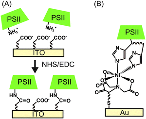 | ||
| Fig. 7 Schematic presentation of (A) electrostatic orientation and covalent immobilisation of PSII using coupling agents of NHS and EDC,28 and (B) immobilisation of PSII via Ni-NTA SAM.22 | ||
Following electrostatic orientation of PSII on the electrodes modified with exposed carboxylates, the electrode was treated with the peptide coupling agents 1-(3-dimethylaminopropyl)-3-ethylcarbodiimide (EDC) and N-hydroxysuccinimide (NHS). Consequently, a covalent amide bond between the protein shell and the SAM was formed (Fig. 7A).28 The covalently bonded PSII was observed to exhibit almost two-fold higher photocurrent density and stability than non-covalentely bound PSII. This study demonstrates that the linkage between the PSII and the electrode surface is critical for electron transfer efficiencies and enzyme stability in PF-PEC studies. TOFs were calculated for the covalent SAM system to be 0.61 s−1 for DET and 4.6 s−1 for MET using DCBQ (entry 3, Table 1). The difference between DET and MET is indicative that further optimisation to PSII immobilisation is possible.
Bare gold surfaces are hydrophobic in nature and do not interact favourably with proteins in direct contact (Section 2.3). However, the surface chemistry of gold can be readily modified by the use of appropriate thiol-containing compounds to form SAMs. For example, PSII with a His-tag on the stromal side of the C-terminus of CP47 or CP4330 can be linked to a gold electrode modified with a thiol-Ni-NTA SAM (Fig. 7B).22,24 The strong affinity of Ni-NTA to the His-tag allows for site-directed immobilisation of PSII onto the electrode. Photocurrent densities of 14 μA cm−2 for MET using DCBQ (entry 4, Table 1)22 and 0.13 μA cm−2 for DET (entry 5, Table 1)24 were reported for Ni-NTA-functionalised flat gold electrodes. Increasing the surface area ratio with nanostructured gold electrodes with a Ni-NTA SAM by 7 and 17-fold, the DET photocurrent densities increased to 0.76 μA cm−2 and 2.4 μA cm−2 (entry 6, Table 1), respectively.24
PSII was also previously integrated into a nanostructured TiO2 electrode; however the mismatch of the redox potentials between the terminal plastoquinones in PSII and the TiO2 conduction band does not allow for DET at the PSII–TiO2 interface. To overcome this obstacle, immobilisation of PSII on a dye-sensitised nanostructured TiO2 electrode was achieved. This TiO2|Ru-dye|PSII electrode requires two photo-excitations (one at PSII and a second at the dye to promote electrons into the conduction band of TiO2) and a photocurrent of 35 μA cm−2 was obtained for MET using DCBQ under white light irradiation (entry 7, Table 1).26
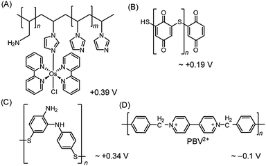 | ||
| Fig. 8 Redox polymers used in PSII PF-PEC studies. (A) Os redox-hydrogel based on poly(vinyl)imidazole,23,38 (B) polymercaptobenzoquinone (pMBQ),25,39 (C) polymercaptoaniline25 and (D) poly-benzyl viologen (PBV2+)33 with their redox potentials (vs. NHE). | ||
Although the use of the Os-based polymer is a promising strategy for PF-PEC studies, it should be mentioned that energy loss is introduced into the system due to the difference in redox potentials between the Os mediator and the PSII quinones. Additionally, the phasing out of noble metal components is ultimately important for the development of future artificial water splitting systems and inexpensive sensors.4
Noble metal-free organic redox polymers have also been investigated for use in PSII PF-PEC.25,33,39 Mercaptobenzoquinone or mercaptoaniline can be electro-polymerized to serve as films of redox polymers on electrodes (Fig. 8B and C).25,39 Photocurrent densities of ∼2.7 μA cm−2 were reported for PSII entrapped in polymercaptobenzoquinone (pMBQ, Fig. 8B) on a gold electrode (entry 9, Table 1). This electrode has been used in photo-bioelectrochemical cells25 and herbicide detection.39 Photocurrent densities obtained from the pMBQ system were lower than that from the system of the Os polymer. However, careful manipulation of the redox levels of redox polymers may enhance photocurrent densities and improve efficiencies in the future.
In one study where LbL assembly was used, the electrode was first modified with a SAM of 3-cyanopropyl triethoxysilane.33 The SAM was then hydrolysed under basic conditions to give rise to negatively charged carboxylates. The poly-benzyl viologen (PBV2+, Fig. 8D), which also serves as an electron mediator, was co-assembled with PSII (PSII has an overall negative charge at neutral pH) onto the modified electrode. Photocurrent densities of 0.5 μA cm−2 were observed for electrodes deposited with two-layer film of PSII and PBV2+ (Fig. 9; entry 10, Table 1). In the same study, PSII and PSI were co-assembled with PBV2+ and poly-lysine benzoquinone by LbL deposition.33 The co-assembled photoanode gave rise to a photocurrent density of 1.2 μA cm−2 in the absence of a bias potential.
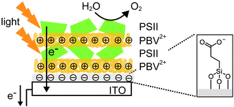 | ||
| Fig. 9 Layer-by-layer (LbL) assembly of PBV2+ and PSII on an ITO-coated glass substrate.33 | ||
2.9 PF-PEC of PSII as an analytical tool
The integration of PSII into PEC systems has enriched the ways in which PSII can be characterised and utilised. PF-PEC can be used to probe PSII by screening its functionality against those of mutant strains or samples that have been treated with exogenous chemicals. For example, PSII treated with a QB-pocket blocking molecule, 3-(3,4-dichlorophenyl)-1,1-dimethylurea (DCMU) was observed to exhibit diminished photocurrent corresponding to one third of that of untreated PSII. The presence of the residual photocurrent reveals a possible alternative electron transfer pathway between the QA and the electrode.27The scope of PSII characterisation offered by PF-PEC can be widened when it is coupled with other complementary techniques. For example, when coupled to a monochromatic light source, PF-PEC can unravel the external quantum efficiency of PSII as a function of the wavelength of light applied. PF-PEC can also be coupled with various spectroscopic techniques to study light activation processes. Spectroelectrochemistry of protein films using either UV-vis or FT-IR spectroscopy coupled to a potentiostat can give electronic and/or vibrational information as a function of applied electrical bias.40
Due to its high sensitivity, PF-PEC can also be used in bio-sensing applications to screen for potential herbicides. A biosensor for triazine- and phenylurea-type herbicides has been reported consisting of immobilised PSII on a graphite working electrode.41 This PF-PEC electrode is reusable and stable (half-life of 24 h), and can detect diuron, atrazine and simazine down to nano-molar concentrations.
A possible future direction for PF-PEC is its use to study the evolution and reconstitution of the PSII OEC. The Mn4Ca cluster can be removed from the PSII and reconstituted with a number of metals and synthetic Mn complexes.42 PF-PEC can be used to characterise Mn depleted and reconstituted PSII systems, and screen for promising water oxidation catalysts in a biological matrix.
3. Bio-inspired PEC water oxidation systems
There are currently large incentives to develop artificial photosynthetic systems in order to put solar fuels into the energy market as a sustainable process to generate renewable fuels. Since PSII sets the benchmarks in water oxidation photocatalysis, many scientists have turned to its remarkable photochemical machinery for inspirations in solar water splitting.Analogous to PSII, the essential components of a synthetic PEC water oxidation system include a water oxidation catalyst (WOC), a photosensitiser, and a mechanism by which multi-charge separation and accumulation can occur. As it stands, substantial optimisation efforts are needed for each of these individual components, as well as in their overall integration, before synthetic systems can start to mimic and perhaps surpass the performance of PSII. The design and activity of various synthetic water splitting PEC systems have been reviewed elsewhere.3 Here, promising examples of WOCs, photosensitisers and charge separation strategies are discussed, and the performance of notable bio-mimetic systems is compared against PSII PF-PEC systems in Table 1.
3.1 Synthetic water oxidation catalysts
Aside from mimicking the impressive TOF and efficient charge-separation of PSII, ideal WOCs for synthetic PEC systems should be chemically robust and deliver large turnover numbers (TONs) to reflect high stability. Importantly, synthetic systems must ultimately be scalable and its components therefore derived from ubiquitous materials.Extensive efforts have been invested in the synthesis of di-, tri- and tetranuclear Mn complexes to mimic the asymmetrical Mn4Ca cluster in PSII. Notably, a structural [Mn3CaO4]6+ cubane OEC mimic was synthesised although no catalytic activity has been reported so far.10 From available data, it has been rationalised that bio-inspired Mn-based water oxidation catalysts require a high Mn-nuclearity and a flexible and robust ligand framework to accommodate and oxidise H2O. They must also extract four electrons in separate steps, and respond to oxidation through ligand exchange or proton-coupled electron-transfer processes. Molecular Mn catalysts have not been developed with great success thus far, presumably due to the difficulty in achieving all of the above requirements. The most active Mn complex reported is that of a Mn cubane catalyst, which can deliver TOF of up to 0.075 s−1 and TON > 1000 at an overpotential of 0.38 V. However, it was later revealed that the Mn compound served solely as a pre-catalyst, cycling between a Mn(II) species to a disordered Mn(III/IV) oxide phase in a ‘self-healing’ process that contributed to its high TON.43
Outperforming the Mn-based catalysts are the Ru-based catalysts, which are among the best performing WOCs reported in the literature. One notable example is a mononuclear Ru complex coordinated to two bidentate 2,2′-bipyridine-6,6′-dicarboxylic acid and two monodentate isoquinoline ligands.44 During catalysis, water coordinates to the Ru as the seventh ligand in the O–Ru–O cleft, consequently bestowing the metal centre with accessible higher oxidation states via proton-coupled electron-transfer. This catalyst can deliver a TOF of >300 s−1 with a TON of >8000 in the presence of the oxidant (NH4)2[Ce(NO3)6] (CeIV), at pH 1.44 In another example, a dinuclear ruthenium catalyst, designed with oxygen rich ligands (inspired by the oxygen rich nature of the PSII Mn4Ca cluster), has been reported to deliver a TOF of 0.1 s−1 with a benchmark TON of >10![[thin space (1/6-em)]](https://www.rsc.org/images/entities/char_2009.gif) 000 in the presence of CeIV at pH 1.45
000 in the presence of CeIV at pH 1.45
Other noteworthy transition metal catalysts include molecular Ir-based catalysts, which exhibit high activity and robustness. In the metal oxide form, iridium and ruthenium catalysts are also noted for their low overpotentials and activity in a wide range of pH values. Despite these promising characteristics, both Ir and Ru are rare and expensive resources that should ultimately be avoided.
Co-based catalysts have received much attention as promising WOCs. For example, a Co-based complex with polytungstate ligands has been reported to exhibit TOF of 5 s−1 (pH 8) in the presence of the oxidant, [Ru(bpy)3]3+, and a TON of 1000 in less than 3 min.46 Amorphous cobalt phosphate and nickel borate on transparent conductive oxides have also received much attention.37,47 Cobalt phosphate was found to exhibit a self-healing process leading to high TON's, but suffers from low a TOF of <0.007 s−1 (pH 7.0).37 Whilst devoid of a self-healing process nickel borate demonstrated long-term stability, and operates at modest overpotentials (425 mV) with high activity (1 mA cm−2 at pH 9.2).47
3.2 Photosensitisers and charge separation
The role of the photosensitiser in a synthetic PEC system is analogous to the chlorophylls and carotenoids within PSII. Ideal photosensitisers are those that are: photostable, exhibit high molar absorptivity, and possess a sufficiently high overpotential as required by the WOC.Although a large number of organic photosensitisers have been reported, [RuII(bpy)3]2+ (bpy = 2,2′-bipyridine) derivatives are most commonly employed in PEC water splitting systems. [RuII(bpy)3]2+ derivatives absorb strongly at 450 to 470 nm due to metal-to-ligand charge transfer, and exhibit an extinction coefficient of 14![[thin space (1/6-em)]](https://www.rsc.org/images/entities/char_2009.gif) 400 M−1 cm−1 at 450 nm in aqueous solution. The reduction potential of the Ru(III) to Ru(II) is 1.26 V vs. NHE, which is sufficient to drive the oxidation of water in neutral pH or basic solution.
400 M−1 cm−1 at 450 nm in aqueous solution. The reduction potential of the Ru(III) to Ru(II) is 1.26 V vs. NHE, which is sufficient to drive the oxidation of water in neutral pH or basic solution.
Following photo-excitation, efficient charge migration must occur to allow for the holes to reach the WOC with minimal energy loss. In PSII, the photo-oxidised P680+ is reduced by the tyrosine–histidine pair in a proton-coupled electron-transfer process, which then efficiently removes electrons from the OEC. It was recently shown that this electron transfer mechanism can be mimicked to some extent by a synthetic triad (Fig. 10A) consisting of a high-potential porphyrin (PF10), a tetracyano porphyrin (TCNP) and a benzimidazole-phenol (Bi-PhOH).48 Using time-resolved spectroscopy, it was demonstrated that the photo-excitation of PF10 in benzonitrile causes a singlet energy transfer to TCNP. The excited TCNP then initiates photoinduced electron transfer to the PF10, which is followed by a further proton-coupled electron-transfer process to the Bi-PhOH, yielding [BiH+–PhO˙–PF10–TCNP˙−] as the final state. This final state has a relatively long lifetime (decays with time constant of 3.8 μs), is thermodynamically capable for water oxidation and may be incorporated into synthetic PEC systems in the future to facilitate charge migration between the photosensitiser and the WOC.
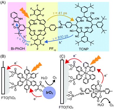 | ||
| Fig. 10 (A) Synthetic triad mimicking elemental steps of energy transfer (yellow arrow) and charge separation (blue arrow) in PSII. Upon irradiation, sequential electron transfers yield the final charge separated [BiH+–PhO˙–PF10–TCNP˙−].48 (B) Dyad system consisting of an immobilised [RuII(bpy)3]2+ photosensitiser coupled to an IrO2·nH2O WOC,34 (C) co-adsorbed system consisting of [RuII(bpy)3]2+ with a mononuclear Ru WOC.35 | ||
3.3 Visible light-driven water splitting systems
Analogous to the PSII PF-PEC systems, a synthetic water oxidation PEC system must couple the WOC to the photosensitiser and accept multiple holes before O2 can be released. Furthermore, the photosensitiser must be coupled to the electrode in a manner that allows for efficient electron injections into the electrode. Both processes must occur extremely efficiently to limit charge recombination. As such, the time-scales of the electron transfer steps and the subsequent charge recombination steps are crucial for water oxidation performance and it is difficult to optimise the first step without also affecting the second step.49Electron injection into the anode can be promoted by the immobilisation of the photosensitiser onto the electrode surface using appropriate anchoring groups and strategies, and the attached WOC can be covalently linked to the photosensitiser. This catalyst-photosensitiser dyad system should promote charge transfer between the two components and increase the overall cell efficiency. A dyad system was constructed consisting of an anatase TiO2 electrode modified with a Ru–polypyridyl-diphosphonate SAM to which IrO2 nanoparticles were coordinated via a pendant malonate group. This system operated with a quantum yield of 0.9%, IPCE of 0.45% and Faraday efficiencies of 20% (Fig. 10B, entry 11 in Table 1) during irradiation. The poor performance was attributed to the fast recombination rates from the conduction band of the anode to the oxidised photosensitiser, compared to the election injection from the WOC to the oxidised photosensitiser.34
In an alternative strategy, the photosensitiser and the WOC can be co-adsorbed onto the electrode surface to promote electronic coupling. A notable example of this approach is the co-adsorption of [RuII(bpy)3]2+ with a mononuclear Ru-based WOC on the surface of a nanoporous TiO2 on FTO electrode (Fig. 10C).35 The ruthenium polypyridyl photosensitiser was anchored to the electrode via phosphonate groups, and the ruthenium WOC was anchored via a silane group that was tethered to its isonicotinamide ligand.35 At pH 6.8 and with an applied bias of 0.2 V vs. NHE, the system produced a photocurrent that translated to a Faraday efficiency of 83%. This result is indicative of favourable coupling between the photosensitiser and WOC (entry 12 in Table 1).
3.4 PSII inspired hybrid materials
In cases where n-type semiconductors have an appropriate band structure for both visible light absorption and water oxidation, the electrode material can be used as the light absorber. WO3 with its band gap of 2.7 eV and valence band at ca. 2.6 V vs. NHE at pH 7 is one such example. However, WO3 dissolves at pH of >4 and also exhibits slow catalysis kinetics and selectivity, rendering it a poor photocatalyst on its own.In a recent study, a heterobimetallic Ti–Ni based precatalyst was deposited on a nanostructured WO3 electrode to form TiO2 for charge separation and NiOx in basic borate buffer for water oxidation catalysis (Fig. 11A).36 Significant enhancements to both the stability of the composite WO3 material and the water oxidation activity were observed. The decrease in onset potential of the electrode due to the Ti–Ni coating can be seen in the photocurrent voltammogram (Fig. 11B, entry 13 in Table 1). It was shown that the TiO2 component of the coating aided in charge separation and also protected the underlying WO3. The NiOx component served as an active electrocatalyst in a borate solution at pH 8 to 9. Despite these improvements, it can be seen that PSII is still the superior ‘per-active-site’ photocatalyst, operating at a lower onset potential and reaching the saturation photocurrent at a lower bias potential (Fig. 11B).
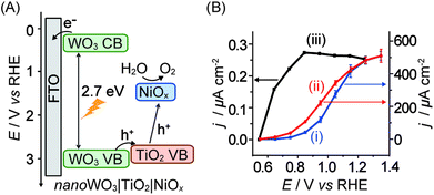 | ||
| Fig. 11 (A) Schematic energy diagram of nanoWO3|TiO2|NiOx for visible light-driven water oxidation (hole transfer from WO3 directly to NiOx is also possible)36 and (B) photocurrent responses of (i) nanoWO3 (ii) nanoWO3|TiO2|NiOx and (iii) mesoITO|PSII electrodes under standardised solar light irradiation (AM 1.5G, 100 mW cm−2; Y.-H. Lai, M. Kato, D. Mersch, E. Reisner, manuscript in preparation). Photocurrents for (i) and (ii) were recorded in an aqueous potassium borate buffered solution (0.1 M, pH 9.2) and for (iii) in a MES buffer solution (0.04 M, pH 6.5). Photocurrents are plotted against the reversed hydrogen electrode (RHE) and RHE can be converted to NHE by adding −0.059 × pH. | ||
Synthetic full water splitting systems bearing biomimetic features have also been recently reported. One such system consists of a ‘self-healing’ cobalt-based WOC coupled to a triple-junction amorphous silicon (3-jn-a-Si) semiconductor as the light harvesting component for overall water-splitting.37 The Co-based WOC, reported to have a structure similar to the Mn4Ca cluster in PSII, was deposited as a thin layer on the surface of the 3-jn-a-Si. When combined with a H2 reduction cathode and irradiated with simulated sunlight, the system was able to convert the majority of the harvested photons to split water into H2 and O2, giving rise to the overall solar-fuel efficiency of 4.7% (entry 14, Table 1). This system stands as an example that bio-inspired complete water splitting devices with respectable efficiency can be assembled.
4. Conclusions and future outlook
Substantial progress was made recently in the development of electrochemical approaches to study PSII. These developments will allow us to obtain more fundamental insights into the function of the protein and to improve our understanding of photo-induced electron transfer at the protein–electrode interface. For example, valuable information about the immobilisation of photoactive PSII can be obtained by comparing DET and MET. The interfacial electron transfer pathways via QA and QB to the electrode surface can be investigated with the use of herbicides. Improvements in PF-PEC will further increase the utility of this technique as an analytical tool to study PSII, in herbicide sensing, and its use as a proof-of-principle water oxidation photocatalyst.In vivo, the overall quantum yield of charge separation in PSII is reported to be above 85%50 and can achieve TOFs two to three orders of magnitude higher than any artificial system in a pH neutral solution. Although isolated PSII in PF-PEC systems does not yet match the performance of in vivo PSII, it is outperforming synthetic systems in terms of ‘per active site’ water oxidation rates and charge separation efficiencies. PSII PF-PEC systems are now also being integrated into complete solar-energy harvesting systems to develop the basic science behind novel artificial photosynthetic devices. An elegant recent example is a biophotovoltaic cell constructed of a PSII-based photoanode coupled to a photosystem I (PSI)-based photocathode, which generated a steady-state photocurrent of ∼1 μA cm−2 under red light irradiation.38
PF-PEC of PSII will be further developed to improve our fundamental understanding of PSII and to assemble ‘proof-of-principle’ PEC systems. However, PSII maintains high TOFs at the cost of limited stability per protein monomer. This is compensated in vivo by self-repair mechanisms, which allow photo-damaged D1 sub-units in PSII to be replaced and recover lost catalytic activity. Scalable and low-cost synthetic PSII-inspired systems with high efficiency and stability are ultimately required to have real world impact in energy conversion.37
Acknowledgements
This work was supported by the U.K. Engineering and Physical Sciences Research Council (EP/H00338X/2 to E.R.), a Marie Curie Intra-European Postdoctoral Fellowship (to J.Z.Z.), a PhD scholarship by the Winton Fund for the Physics of Sustainability (to N.P.) and the University of Cambridge. We thank Professor A. William Rutherford for fruitful discussions on PSII over the years.Notes and references
- Y. Umena, K. Kawakami, J.-R. Shen and N. Kamiya, Nature, 2011, 473, 55–60 CrossRef CAS PubMed.
- N. Nelson and C. F. Yocum, Annu. Rev. Plant Biol., 2006, 57, 521–565 CrossRef CAS PubMed.
- J. R. Swierk and T. E. Mallouk, Chem. Soc. Rev., 2013, 42, 2357–2387 RSC.
- A. Badura, T. Kothe, W. Schuhmann and M. Rögner, Energy Environ. Sci., 2011, 4, 3263–3274 CAS.
- F. Wang, X. Liu and I. Willner, Adv. Mater., 2013, 25, 349–377 CrossRef CAS PubMed.
- O. Yehezkeli, R. Tel-Vered, D. Michaeli, I. Willner and R. Nechushtai, Photosynth. Res., 2013 DOI:10.1007/s11120-013-9796-3.
- K. N. Ferreira, T. M. Iverson, K. Maghlaoui, J. Barber and S. Iwata, Science, 2004, 303, 1831–1838 CrossRef CAS PubMed.
- S. Ogami, A. Boussac and M. Sugiura, Biochim. Biophys. Acta, 2012, 1817, 1322–1330 CrossRef CAS PubMed.
- T. Cardona, A. Sedoud, N. Cox and A. W. Rutherford, Biochim. Biophys. Acta, 2012, 1817, 26–43 CrossRef CAS PubMed.
- J. S. Kanady, E. Y. Tsui, M. W. Day and T. Agapie, Science, 2011, 333, 733–736 CrossRef CAS PubMed.
- G. Ananyev and G. C. Dismukes, Photosynth. Res., 2005, 84, 355–365 CrossRef CAS PubMed.
- E. Romero, I. H. M. van Stokkum, V. I. Novoderezhkin, J. P. Dekker and R. van Grondelle, Biochemistry, 2010, 49, 4300–4307 CrossRef CAS PubMed.
- A. Guskov, J. Kern, A. Gabdulkhakov, M. Broser, A. Zouni and W. Saenger, Nat. Struct. Mol. Biol., 2009, 16, 334–342 CAS.
- G. Renger and T. Renger, Photosynth. Res., 2008, 98, 53–80 CrossRef CAS PubMed.
- T. Shibamoto, Y. Kato, M. Sugiura and T. Watanabe, Biochemistry, 2009, 48, 10682–10684 CrossRef CAS PubMed.
- F. Rappaport, M. Guergova-Kuras, P. J. Nixon, B. A. Diner and J. Lavergne, Biochemistry, 2002, 41, 8518–8527 CrossRef CAS PubMed.
- A. R. Holzwarth, M. G. Müller, M. Reus, M. Nowaczyk, J. Sander and M. Rögner, Proc. Natl. Acad. Sci. U. S. A., 2006, 103, 6895–6900 CrossRef CAS PubMed.
- A. W. Rutherford, Trends Biochem. Sci., 1989, 14, 227–232 CrossRef CAS PubMed.
- N. Ishida, M. Sugiura, F. Rappaport, T.-L. Lai, A. W. Rutherford and A. Boussac, J. Biol. Chem., 2008, 283, 13330–13340 CrossRef CAS PubMed.
- A. Volgusheva, S. Styring and F. Mamedov, Proc. Natl. Acad. Sci. U. S. A., 2013, 110, 7223–7228 CrossRef CAS PubMed.
- F. A. Armstrong and J. Hirst, Proc. Natl. Acad. Sci. U. S. A., 2011, 108, 14049–14054 CrossRef CAS PubMed.
- A. Badura, B. Esper, K. Ataka, C. Grunwald, C. Wöll, J. Kuhlmann, J. Heberle and M. Rögner, Photochem. Photobiol., 2006, 82, 1385–1390 CrossRef CAS PubMed.
- A. Badura, D. Guschin, B. Esper, T. Kothe, S. Neugebauer, W. Schuhmann and M. Rögner, Electroanalysis, 2008, 20, 1043–1047 CrossRef CAS.
- N. Terasaki, M. Iwai, N. Yamamoto, T. Hiraga, S. Yamada and Y. Inoue, Thin Solid Films, 2008, 516, 2553–2557 CrossRef CAS.
- O. Yehezkeli, R. Tel-Vered, J. Wasserman, A. Trifonov, D. Michaeli, R. Nechushtai and I. Willner, Nat. Commun., 2012, 3, 1741–1747 Search PubMed.
- K. K. Rao, D. O. Hall, N. Vlachopoulos, M. Grätzel, M. C. W. Evans and M. Seibert, J. Photochem. Photobiol., B, 1990, 5, 379–389 CrossRef CAS.
- M. Kato, T. Cardona, A. W. Rutherford and E. Reisner, J. Am. Chem. Soc., 2012, 134, 8332–8335 CrossRef CAS PubMed.
- M. Kato, T. Cardona, A. W. Rutherford and E. Reisner, J. Am. Chem. Soc., 2013, 135, 10610–10613 CrossRef CAS PubMed.
- K. Alcantara, B. Munge, Z. Pendon, H. A. Frank and J. F. Rusling, J. Am. Chem. Soc., 2006, 128, 14930–14937 CrossRef CAS PubMed.
- M. Sugiura and Y. Inoue, Plant Cell Physiol., 1999, 40, 1219–1231 CrossRef CAS PubMed.
- T. Tyystjärvi, E.-M. Aro, C. Jansson and P. Mäenpää, Plant Mol. Biol., 1994, 25, 517–526 CrossRef.
- M. Vittadello, M. Y. Gorbunov, D. T. Mastrogiovanni, L. S. Wielunski, E. L. Garfunkel, F. Guerrero, D. Kirilovsky, M. Sugiura, A. W. Rutherford, A. Safari and P. G. Falkowski, ChemSusChem, 2010, 3, 471–475 CrossRef CAS PubMed.
- O. Yehezkeli, R. Tel-Vered, D. Michaeli, R. Nechushtai and I. Willner, Small, 2013, 9, 2970–2978 CrossRef CAS PubMed.
- W. J. Youngblood, S.-H. A. Lee, Y. Kobayashi, E. A. Hernandez-Pagan, P. G. Hoertz, T. A. Moore, A. L. Moore, D. Gust and T. E. Mallouk, J. Am. Chem. Soc., 2009, 131, 926–927 CrossRef CAS PubMed.
- Y. Gao, X. Ding, J. Liu, L. Wang, Z. Lu, L. Li and L. Sun, J. Am. Chem. Soc., 2013, 135, 4219–4222 CrossRef CAS PubMed.
- Y.-H. Lai, T. C. King, D. S. Wright and E. Reisner, Chem. – Eur. J., 2013, 19, 12943–12947 CrossRef CAS PubMed.
- S. Y. Reece, J. A. Hamel, K. Sung, T. D. Jarvi, A. J. Esswein, J. J. H. Pijpers and D. G. Nocera, Science, 2011, 334, 645–648 CrossRef CAS PubMed.
- T. Kothe, N. Plumeré, A. Badura, M. M. Nowaczyk, D. A. Guschin, M. Rögner and W. Schuhmann, Angew. Chem., Int. Ed., 2013, 52, 14233–14236 CrossRef CAS PubMed.
- J. Maly, J. Masojidek, A. Masci, M. Ilie, E. Cianci, V. Foglietti, W. Vastarella and R. Pilloton, Biosens. Bioelectron., 2005, 21, 923–932 CrossRef CAS PubMed.
- P. A. Ash and K. A. Vincent, Chem. Commun., 2012, 48, 1400–1409 RSC.
- M. Koblížek, J. Malý, J. Masojídek, J. Komenda, T. Kučera, M. T. Giardi, A. K. Mattoo and R. Pilloton, Biotechnol. Bioeng., 2002, 78, 110–116 CrossRef PubMed.
- S. I. Allakhverdiev, U. Ozdemir, J. Harnois, N. Karacan, S. Hotchandani, V. V. Klimov, N. Murata and R. Carpentier, Photochem. Photobiol., 1999, 70, 57–63 CrossRef CAS.
- R. K. Hocking, R. Brimblecombe, L.-Y. Chang, A. Singh, M. H. Cheah, C. Glover, W. H. Casey and L. Spiccia, Nat. Chem., 2011, 3, 461–466 CAS.
- L. Duan, F. Bozoglian, S. Mandal, B. Stewart, T. Privalov, A. Llobet and L. Sun, Nat. Chem., 2012, 4, 418–423 CrossRef CAS PubMed.
- Y. Xu, A. Fischer, L. Duan, L. Tong, E. Gabrielsson, B. Åkermark and L. Sun, Angew. Chem., Int. Ed., 2010, 49, 8934–8937 CrossRef CAS PubMed.
- Q. Yin, J. M. Tan, C. Besson, Y. V. Geletii, D. G. Musaev, A. E. Kuznetsov, Z. Luo, K. I. Hardcastle and C. L. Hill, Science, 2010, 328, 342–345 CrossRef CAS PubMed.
- M. Dincă, Y. Surendranath and D. G. Nocera, Proc. Natl. Acad. Sci. U. S. A., 2010, 107, 10337–10341 CrossRef PubMed.
- J. D. Megiatto, A. Antoniuk-Pablant, B. D. Sherman, G. Kodis, M. Gervaldo, T. A. Moore, A. L. Moore and D. Gust, Proc. Natl. Acad. Sci. U. S. A., 2012, 109, 15578–15583 CrossRef CAS PubMed.
- A. N. M. Green, E. Palomares, S. A. Haque, J. M. Kroon and J. R. Durrant, J. Phys. Chem. B, 2005, 109, 12525–12533 CrossRef CAS PubMed.
- A. Cuni, L. Xiong, R. Sayre, F. Rappaport and J. Lavergne, Phys. Chem. Chem. Phys., 2004, 6, 4825–4831 RSC.
Footnote |
| † Present address: Division of Environmental Materials Science, Hokkaido University, Japan. |
| This journal is © The Royal Society of Chemistry 2014 |

