Miniaturized nuclear magnetic resonance platform for detection and profiling of circulating tumor cells
Cesar M.
Castro
*ab,
Arezou A.
Ghazani
a,
Jaehoon
Chung
a,
Huilin
Shao
a,
David
Issadore†
a,
Tae-Jong
Yoon‡
a,
Ralph
Weissleder
abc and
Hakho
Lee
*a
aCenter for Systems Biology, Massachusetts General Hospital, Harvard Medical School, Boston, MA 02114, USA. E-mail: Castro.Cesar@mgh.harvard.edu; hlee@mgh.harvard.edu; Tel: +1 617-726-8226
bMassachusetts General Hospital Cancer Center, Boston, MA 02114, USA
cDepartment of Systems Biology, Harvard Medical School, Boston, MA 02114, USA
First published on 27th June 2013
Abstract
Accurate detection and profiling of circulating tumor cells (CTCs) is a highly sought after technology to improve cancer management. Such “liquid biopsies” could offer a non-invasive, repeatable window into each patient's tumor, facilitating early cancer diagnosis and treatment monitoring. The rarity of CTCs, approximated at 1 CTC for every billion peripheral blood cells, however, poses significant challenges to sensitive and reliable detection. We have recently developed a new micro-nuclear magnetic resonance (μNMR) platform for biosensing. Through the synergistic integration of microfabrication, nanosensors, and novel chemistries, the μNMR platform offers high detection sensitivity and point-of-care operation, overcoming technical barriers in CTC research. We herein review the μNMR technology with emphasis on its application to CTC detection. Recent advances in the sensing technology will be summarized, followed by the description of the dynamic interplay between our preclinical and clinical CTC studies.
I. Introduction
Mounting evidence supports the view that molecular profiling of cancer is a preferred method of classifying tumors, stratifying patients for targeted therapies, assessing treatment efficacy, and achieving clinical benefit.1–4 Failure to detect molecular differences of otherwise histologically identical tumors can also lead to underpowered clinical trials,5 thus creating missed opportunities for identifying effective therapies in specific patient subsets. Furthermore, molecular profiling is helpful in assessing treatment efficacy over time but serial surgical biopsies raise morbidity, compliance, safety and cost concerns. For these reasons, there has been a desire to shift to more clinically available samples, notably peripheral blood where circulating tumor cells (CTCs) can be analyzed.Attempts to identify CTC have gained traction in solid tumors,6–9 but their reliable detection has been challenging using currently accepted enumeration techniques. The most commonly used cytometric method, Cell Search, is FDA-approved and based on enumeration of epithelial cells using anti-epithelial cell adhesion molecule (EpCAM) antibodies and subsequent staining for visualization.10 Its comparatively lengthy isolation and staining steps, however, are accompanied by considerable cell loss (∼20–40%).11,12 It is generally accepted that EpCAM-based detection has low sensitivity in EpCAM-negative cancers, which may explain why a considerable fraction (up to 70% in some studies) of patients with metastatic epithelial malignancies fail to exhibit detectable CTCs using such methods. This is especially the case for aggressive tumor cells, which often downregulate EpCAM during epithelial-mesenchymal transition (EMT).13 Novel and rapid detection strategies extending beyond EpCAM are needed to promote rare cancer cell studies. Given that some trials are starting to stratify and tailor patient therapy based on CTC changes (clinicaltrials.gov ID: NCT00382018), this is becoming increasingly important and relevant today.
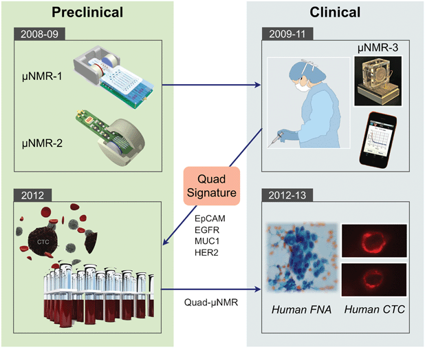
We previously developed a novel sensing technology, termed micro-nuclear magnetic resonance (μNMR), which enables rapid and highly sensitive biomarker detection.14μNMR exploits magnetic resonance technology (similar to a clinical MRI scan) to detect cells labeled with immunospecific magnetic nanoparticles (MNPs). These nanoparticles are typically much smaller (tens of nm) compared to larger beads used for immunoseparation and are superparamagnetic, rather than ferromagnetic. Samples containing MNP-labeled cells display faster relaxation of NMR signals due to local magnetic fields created by MNPs.15 Since signal detection is based on magnetic interactions, μNMR can be performed with minimal sample purification steps, which reduces cell loss and simplifies assay procedures.14 Through systematic optimization of nanoagents,16–20 conjugation chemistry,21,22 and NMR detectors,14,23,24 the μNMR platform has been considerably advanced, enabling sensitive and robust detection on a wide range of targets, including nucleic acids,25,26 proteins,14 exosomes,27 bacteria,28–30 and tumor cells.31 Most recently, the platform has been adopted to detect and profile CTCs for point-of-care read outs. By leveraging the synergies between the preclinical and clinical spaces (Fig. 1), μNMR technology has enabled robust detection and molecular profiling of CTC.32,33 This article will comprehensively review μNMR technology, detailing recent technical developments and translational work.
II. μNMR technology
Detection of MNP-labeled cells can be facilitated by exploiting the “T2-shortening” effect of MNPs in NMR measurements.15 When placed in static, polarizing magnetic fields for NMR detection, MNPs produce local dipole fields with strong spatial dependence, which efficiently destroys the coherence in the spin–spin relaxation of water protons. MNP-labeled objects consequently cause faster decay of NMR signal, or shorter transverse relaxation time T2, than non-targeted ones (Fig. 2).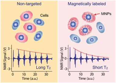 | ||
| Fig. 2 Principle of cellular detection with μNMR. Cancer cells tagged with MNPs can accelerate the transverse relaxation of water protons. Compared to the non-tagged samples (left), the NMR signal will decay faster in time domain (right), providing a sensing mechanism. (Reproduced with permission from ref. 14. Copyright 2008 Nature Publishing Group.) | ||
The capability of MNPs to induce T2 changes is defined as transverse relaxivity (r2).34 With MNPs in solution, the relaxation rate (R2 = 1/T2) can be expressed as16
 | (1) |
 | (2) |
• MNPs engineered for high transverse relaxivity. Pronounced changes in the relaxation rate (R2) will occur when biological targets are labeled with MNPs of high transverse relaxivity (r2).35 Making magnetically stronger MNPs will benefit measurements, as r2 concomitantly increases with the magnetic moment of particles.36,37
• Efficient MNP labeling on cells. Detection sensitivity will improve by increasing the number (NC) of MNPs per cell, which calls for the optimization of MNP-labeling strategy.
• Miniaturized NMR probes. Higher sensitivity can be achieved by decreasing the NMR detection volume (V), as it can effectively increase the analyte concentration (NC/V) and lead to large ΔR2. This is the most important rationale for implementing a miniaturized NMR system.
The following sections describe how each of these aspects were addressed during μNMR development, particularly as they relate to CTC detection.
II.1. New magnetic nanoparticles
The transverse relaxivity (r2) of MNPs is known to scale as r2 ∼ dp2Mp2, where dp and Mp denote particle size and magnetization, respectively.36,37 Efforts to improve r2 have thus focused on synthesizing magnetically stronger and larger particles.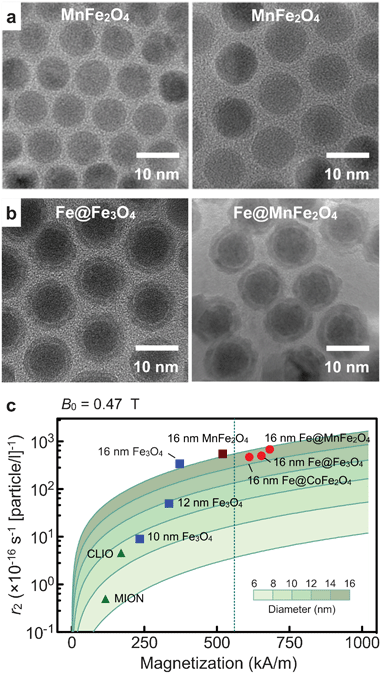 | ||
| Fig. 3 Magnetic nanoparticles engineered for high transverse relaxivity (r2). (a) Transmission electron micrograph (TEM) images of Mn-doped magnetite (MnFe2O4) particles. Smaller particles (left) were used as a seed to grow bigger particles (right). (b) TEM micrographs of Fe-MNPs. These particles have an elemental Fe-core passivated with a ferrite shell. The shell prevents the core from oxidation, and impart additional magnetic moments to the particle. Note that the shell can be metal-doped to further enhance magnetization. (c) The r2 values of various types of MNPs were mapped as a function of both the particle size (d) and the saturation magnetization (Ms). As expected from the outer-sphere theory (solid line), the r2 values of ferrite MNPs increased with the particle size (blue squares). Among ferrite, MnFe2O4 MNPs have the highest r2 due to their high Ms, but these values were upper limited by the bulk Ms of MnFe2O4 (dotted line). Fe-core MNPs, because of their stronger magnetization, passed the boundary and achieved higher r2 relaxivities, with Fe@MnFe2O4 MNPs assuming the highest value. CLIO, cross-linked iron oxide nanoparticle; MION, monocrystalline iron oxide nanoparticle. (Adapted with permission from ref. 16. Copyright 2009 National Academy of Sciences, USA. Reproduced with permission from ref. 18. Copyright 2011 John Wiley and Sons, Inc.) | ||
Fig. 3c compares the r2 values of different types of magnetite MNPs. For a given particle composition, r2 values increases with particle size (dp). Interestingly, Mp also increases with dp, possibly due to reduced surface effect (e.g., spin-canting) in larger particles. Enlarging particle size, therefore, improved r2 values much faster than expected. For a given particle size, MnFe2O4 MNPs assumed the highest r2 (= 6 × 10⁻¹⁴ L s−1 per particle) on account of their high magnetization. The maximum r2 of ferrite MNPs, however, was limited by the bulk magnetization of MnFe2O4.
We recently developed a new type of Fe-MNP construct that maximizes particle magnetization.18 The particle has a hybrid structure (Fe@ferrite), consisting of an elemental Fe-core and a protective ferrite shell. The synthetic method has been optimized to make large Fe-cores and preserve them in subsequent processes. The Fe-core particles were first formed through the thermal decomposition of iron (0) pentacarbonyl. The particle size increased in proportional to the reaction temperature, which could be attributed to the higher reactivity of Fe ions at elevated temperatures.45 Applying this approach, we could prepare Fe MNPs with diameters up to 16 nm while maintaining relative size variations at <5%. We next coated the Fe-core with a ferrite shell by carrying out ferrite-synthesis in the presence of as-prepared Fe MNPs. As in ferrite MNP synthesis, the shell could be metal-doped (Fe@MFe2O4, M = Mn, Co, Fe; Fig. 3c) to further improve particle magnetization. The resulting particles showed high stability against oxidation with negligible changes in particle shape and magnetic properties. Importantly, the Mp values of Fe@MFe2O4 particles were higher than those of magnetite-based MNPs, which led to >400% increase in r2 (Fig. 3c).
II.2. Bio-orthogonal strategy for efficient MNP labeling
Besides improving the physical properties of MNPs, our group has also developed more efficient methods for MNP-labeling. A conventional approach uses MNPs pre-conjugated with target-specific affinity ligands,14 which often requires extensive optimization of both the affinity ligands and the conjugation methods for each new target. This becomes cumbersome when larger numbers of markers are being investigated or when routine clinical use is contemplated since immune-conjugates typically have a shorter half-life compared to unlabeled antibodies.Recently, we developed a novel targeting strategy, BOND (BioOrthogonal Nanoparticle Detection), that is modular, broadly applicable, and amplifies MNP-binding to biological targets.21 BOND is based on {4 + 2} Diels–Alder cycloaddition, notably the reaction between tetrazine (Tz) and trans-cyclooctene (TCO; Fig. 4a).46 The reaction is fast, irreversible (covalent) and can be performed at room temperature without catalyst (historically copper). BOND chemistry has been adapted to cell-labeling with MNP (Fig. 4b), wherein cells are pre-targeted with TCO-modified antibodies and subsequently incubated with Tz-loaded MNPs (Tz-MNPs). Multiple TCO tags (usually ∼20) can be incorporated onto an antibody without loss of affinity. Consequently, the antibodies function as scaffolds to promote multiple attachment of Tz-MNPs. Furthermore, compared to using direct antibody-MNP conjugates, the two-step approach (i.e., sequential application of antibody-TCO and Tz-MNPs) allows for easier access of antibodies to cell surface. More target markers thus can be occupied by separate antibody scaffolds, which leads to denser MNP-packing. Indeed, flow cytometry measurements showed that BOND yielded ∼15-fold improvements in MNP-loading on cells, compared to labeling with antibody-MNP direct conjugates (Fig. 4c). The trend was further confirmed in μNMR-based cell detection (Fig. 4d); the BOND method yielded more pronounced R2 changes and improved the cellular detection limit.
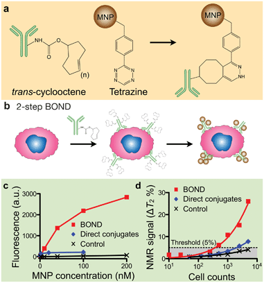 | ||
| Fig. 4 Bioorthogonal nanoparticle detection (BOND). (a) The method is based on the Diels–Alder cycloaddition between trans-cyclooctene (TCO) and tetrazine (Tz). (b) Cells are pre-labeled with TCO-antibodies and targeted with Tz-MNPs. The antibody provides sites for multiple MNP binding. (c, d) Compared to the direct targeting with MNP-antibody conjugates, BOND method enabled higher MNP loading on target cells as confirmed by fluorescent (c) and μNMR (d) measurements. (Adapted with permission from ref. 21. Copyright 2010 Nature Publishing Group.) | ||
To further improve BOND-mediated labeling, we focused on TCO modification of secondary IgG (and not primary) antibodies.33 Specifically, cells are: (1) first labeled with primary antibodies (typically requiring lesser amounts); (2) targeted with secondary IgG antibodies previously modified with TCO and (3) then coated with MNPs. This approach spares excessive consumption of valuable primary antibodies, amplifies signal, and increases sensitivity given that multiple secondary antibodies bind to one primary antibody; these are key ingredients for successful CTC detection.
II.3. Miniaturized NMR system
We have developed different versions of miniaturized NMR devices for point of care measurements. System miniaturization affords the following advantages: 1) lowering detection limits by reducing sample volumes and effectively increasing analyte concentrations (eqn (2)); 2) increasing sensitivity of NMR probes (coils) since smaller coils generate stronger radio-frequency (RF) magnetic fields per unit current;47 and 3) enabling the use of small, portable magnets to generate NMR magnetic fields as NMR probes become smaller.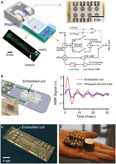 | ||
| Fig. 5 μNMR system development. (a) μNMR-1: The system consists of an array of microcoils for NMR detection, microfluidic channels for sample handling, embedded NMR electronics, and a permanent magnet. (b) μNMR-2 (left): A solenoidal coil is embedded along with a microfluidic channel. The entire bore of the coil is available to samples, maximizing the filling factor (≈ 1). (right) The new coil offered >350% enhancement in NMR signal, compared to a similar coil wrapped around a tubing. (c) A NMR coil was integrated into a sophisticated microfluidic system. MNP-labeling, sample washing and NMR detection can be performed on-chip. (d) The entire NMR setup can be potentially packaged as a hand-held device, using a custom-designed IC (integrate circuit) chip. (Reproduced with permission from ref. 14 and 27. Copyright 2008, 2012 Nature Publishing Group. Adapted with permission from ref. 16. Copyright 2009 National Academy of Sciences, USA. Reproduced with permission from ref. 23. Copyright 2010 IEEE.) | ||
In the second prototype (μNMR-2), we focused on improving the detection sensitivity by optimizing the NMR probe (Fig. 5b).16,17 We opted for solenoidal coils as the probe format, as they could produce more homogeneous RF magnetic fields and has less electrical resistance than planar coils. Unlike the conventional design wherein the coils were wound around capillary tubes, we completely embedded the solenoidal coils into the fluidic system. In this approach, the coils were first prepared by winding wires around a polyethylene tube. The coil-tube assembly was then cast-molded by pouring polydimethylsiloxane (PDMS). After PDMS curing, the tube was extracted to open up fluidic channels. With this new design, the entire coil bore can be filled with samples to maximize NMR signal level. Combined with lower electrical noise of the coils, the new probe showed 10-fold higher mass detection sensitivity than μNMR-1 and enabled highly sensitive detection. Furthermore, the PDMS-coil block could be seamlessly and easily integrated with other fluidic components (e.g., pumps, pneumatic valves, filters), enabling on-chip sample processing and NMR detection (Fig. 5c).
We also sought to further miniaturize our NMR system for portable operations. Specifically, we custom-designed a CMOS (complementary-metal-oxide semiconductor) chip (1.4 × 1.4 mm2) that integrates all necessary NMR electronics (Fig. 5d).23 The whole NMR setup was packaged as a hand-held device, making μNMR-2 the world's smallest NMR system.
For μNMR-3, we adopted an alternative, software-based approach: the ƒ0 was monitored before each measurement and the measurement settings were accordingly adjusted.24Fig. 6a summarizes the tracking algorithm. When a measurement starts, the system sweeps the excitation frequency ƒ to find the resonance frequency ƒ0. For each ƒ, the system measures the free induction decay of the NMR signal and transforms the signal into the frequency domain via fast Fourier transformation. A peak-finding routine then determines the frequency offset Δƒ (= ƒ − ƒ0). The whole process iterates until Δƒ reaches a target value, and a standard NMR measurement is then performed. To reduce processing time, the tracking routine is further divided into two parts: a coarse and a fine tracker. For the first measurement, the system will conduct both tracking methods. In the subsequent operations, however, the fine tracker will find the resonance frequency, based on the ƒ0 in the immediate previous measurement. The developed method guarantees reliable and robust μNMR measurements. For example, when the tracking routine was turned off, R2 values fluctuated up to 200% of its initial value in a typical laboratory setting. With tracking on, the fluctuation was <3% (Fig. 6b).
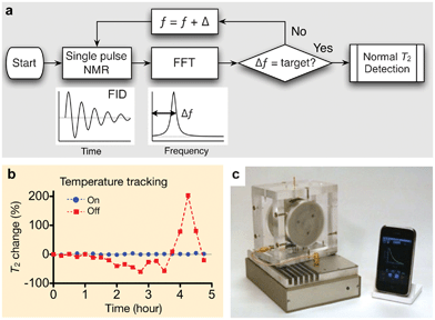 | ||
| Fig. 6 μNMR-3 designed for clinical applications. (a) Algorithm for robust NMR measurement. The routine keeps track of the NMR frequency and automatically adjust ƒ (RF excitation frequency), maintaining a constant frequency offset (Δƒ). FID, free induction decay; FFT, fast Fourier transformation. (b) With the frequency tracking turned on, the measured T2 values of the same sample showed <1% variation, whereas T2 values fluctuated >200% without such scheme. (c) μNMR-3 system for point-of-care operation, featuring automatic system configuration and a smartphone interface. The system was used in the recent clinical trial. (Reproduced with permission from ref. 24. Copyright 2011 RSC Publishing.) | ||
The μNMR-3 has other important aspects for practical use. The electronics were assembled using off-the-shelf integrated circuit (IC) parts (e.g., microcontrollers, RF synthesizers), which reduced system costs (<$200) while improving its programmability. Moreover, the electronics interfaced with a mobile terminal (e.g., smartphones, tablet computers) for system control (Fig. 6c). A customized application program was implemented to allow for system operation and data-logging with minimal input from end-users. For translational testing, μNMR-3 has anchored our recent preclinical and clinical work as detailed in the following section.
III. Clinical investigation
III.1. Determining a unique tumor protein panel for detection
Selection of appropriate protein biomarkers for ubiquitous cancer detection has been challenging for a number of reasons including (i) absence of unique cancer specific proteins, (ii) low abundance levels of certain proteins, (iii) the molecular heterogeneity of tumors,48,49 (iv) temporal changes of molecular profiles among others. Since it appears unlikely that a single protein can identify all cancers, the focus has shifted towards multiplexed testing. With μNMR-3 in place to support our first-in-human studies, we profiled a wide array of solid epithelial tumors grounded in the typical clinical workflow of an interventional radiology department.31 We applied μNMR-3 to fine needle aspirates (FNA) from 50 patients presenting to the Massachusetts General Hospital with suspected intra-abdominal malignancies (Fig. 7). Notably, with one FNA pass we quantitated the protein expression levels of nine well-established cancer markers and one leukocyte marker. We identified a four marker panel set (MUC-1 + EGFR + HER2 + EpCAM), coined quad-marker, that conferred a 96% diagnostic accuracy compared to clinical pathology interpretation of their paired core biopsies. To eliminate potential sources of error and data over-fitting, we tested our quad marker in 20 additional patients. μNMR-3 correctly diagnosed all 20 patients in the validation set, supporting the quad-marker as a reliable signature of solid epithelial tumors. The rapid readouts (∼1 h) and user friendly operation of the smartphone interface aligned with our pre-clinical experiences.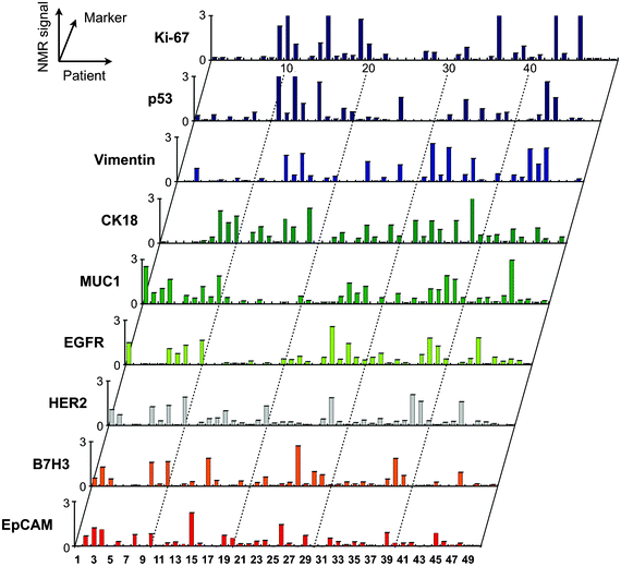 | ||
| Fig. 7 Profiling of tumor cells using the μNMR platform. Single fine-needle aspirates were obtained from patients, and were tagged via the BOND strategy for μNMR detection. The profiling results indicate a high degree of heterogeneity in protein expression both across the different patient samples and even with the same tumor. (Reproduced with permission from ref. 31. Copyright 2011 American Association for the Advancement of Science AAAS.) | ||
III.2. Preclinical optimization of quad-μNMR for CTC testing
We integrated quad marker analyses into our platform (quad-μNMR) and explored its potential to identify CTCs.32 We hypothesized that applying a quad-marker cocktail for simultaneous cellular targeting and testing would prove superior to multiplexing. In the following sections, we discuss steps taken to optimize our quad-μNMR assay to detect CTC directly in whole blood. This initially occurred under highly regulated laboratory conditions followed by testing on patient-derived clinical samples.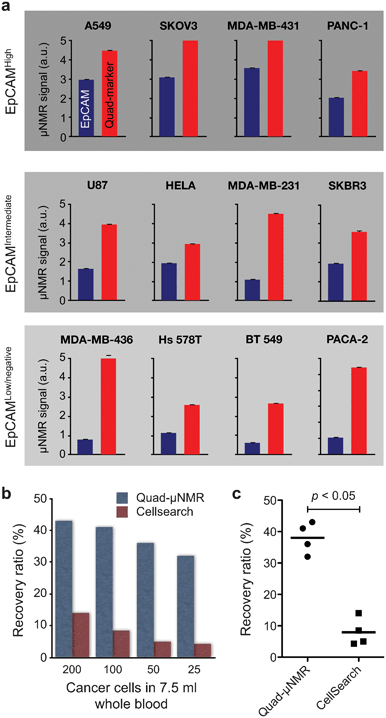 | ||
| Fig. 8 Performance of quad-μNMR and comparison with CTC gold standard. (a) Comparison of EpCAM-only and quad marker CTC detection using μNMR. Across all cell lines with different EpCAM-expression, quad-μNMR (red bars) showed higher NMR signals than EpCAM-only (blue bars) detection. (b) Using quad-μNMR, the average CTC recovery rate was 38% across the various cell concentrations assessed (i.e., 200, 100, 50 and 25 spiked cells). Identical experiments performed using the CellSearch detection system showed an average recovery rate of 9.1%. (c) Quad-μNMR indeed showed higher CTC detection sensitivity (p < 0.05) than CellSearch system. (Adapted with permission from ref. 32. Copyright 2012 Neoplasia Press.) | ||
We also compared quad-μNMR to CellSearch and noted an average recovery rate of 9.1% across all concentrations accessed (i.e. 200, 100, 50 and 25 spiked cells) for the latter (Fig. 8b). In contrast, quad-μNMR demonstrated an average recovery rate of 38% across the various cell concentrations, leading to higher CTC detection sensitivity (p < 0.05) in all cases (Fig. 8c).32 In our preclinical studies, the detection sensitivity of quad-μNMR was 400% fold higher than CellSearch. Quad-μNMR was even more sensitive in the low EpCAM expressing breast cell line, MDA-MB-436, with known EMT behavior.
III.3. Utility of quad-μNMR in clinical studies
To examine the clinical performance of quad-μNMR, we pursued a pilot study using freshly collected peripheral blood from 15 patients with advanced ovarian cancer.32 Quad-μNMR's broader dynamic range of CTC enumeration correlated well with clinical metrics. For example, average CTC counts were higher in more advanced cases such as stage IV, platinum resistant and progressive disease, and in patients not pursuing active therapy. Quad-μNMR also performed better than EpCAM-based CellSearch, reporting higher CTC counts. Studies are under way to validate these findings in ovarian cancer and to explore the utility of quad-μNMR for minimally invasive monitoring of response or early recurrence.III.4. Comparing CTC with matched distal metastases
A key aspiration of many cancer investigators is understanding how well CTC protein profiles correlate with their metastatic deposits. Strong associations could justify leveraging CTCs for diagnostic and potentially pharmacodynamic monitoring rather than pursuing more invasive biopsies. Using μNMR, we recently demonstrated that comparing the protein profiles of CTCs with their respective FNA was feasible.33 First, quad-μNMR detected CTCs in all 21 enrolled subjects with a range of ∼3 to 27 CTC/mL.33 More CTCs were detected (1) in patients with metastatic disease than with locally advanced cancers, and (2) in patients with progressive disease (∼10 CTC/mL) than clinical responders (∼4 CTC/mL). Beyond enumeration, we used quad-μNMR to compare the molecular profiles of CTCs with their matched distal metastasis. Cellular expression levels of EpCAM, EGFR, HER2 and vimentin were positive in 67%, 62%, 76%, and 76% of CTC samples, respectively (Fig. 9). The expression of vimentin in patients with worsening clinical trajectories was 50% lower compared to patients with stable or improving trajectories, which supports associations between EMT and aggressive clinical course. Overall, our data suggests that, across a wide spectrum of intra-abdominal solid epithelial tumors, the molecular profiles of CTCs are not similar to their matched distal metastases (Fig. 9). As such, “benign” results in one specimen type would still demand testing the other (i.e. CTC may not be adequate diagnostic surrogates to obviate additional testing). We are currently examining whether such discrepancies hold true by testing larger numbers of subjects and focusing on specific cancer types (e.g., lung and melanoma). | ||
| Fig. 9 Comparison of molecular profiles between CTCs and biopsy from the site of metastasis. Each column represents a patient sample. CTC results (top) are categorized as positive (+) or negative (−) for the expression of a given marker. Results from the biopsy from the site of metastasis (bottom) are similarly indicated as positive or negative. In each subject, concordant test result (i.e. both CTC and biopsy positive or both negative) is designated in green. Discordant results are shown in pink. (Reproduced with permission from ref. 33. Copyright 2013 Elsevier Inc.) | ||
IV. Conclusion
The clinical application of the μNMR technology would fulfill many (if not all) of the key requirements desirable for biodiagnostic technologies, namely: assay sensitivity, selectivity, versatility, low cost and portability.51 Manufacturing costs from reusable NMR components (<$200) and the disposable microfluidic chip (<$1) also render μNMR technology a practical and scalable option. These contributions will be important because they are all predicated on the use and analyses of human specimens attained through minimally invasive means – an unmet need for serial studies. Opportunities from our CTC work and those of others include better powered trials, improved tumor monitoring, and rational selection of therapies at the relevant time with higher potential for clinical benefit. We anticipate μNMR technology, with its ability for molecular profiling of CTCs at point-of-care settings, would provide an important step forward beyond enumeration to the clinical deployment of personalized and highly specific cancer therapies.Acknowledgements
The authors thank N. Sergeyev for providing dextran-coated iron oxide nanoparticles; Y. Fisher-Jeffes for reviewing the manuscript; R. M. Westervelt (Harvard) for helpful discussion; Ham group (Harvard) for implementing CMOS ICs. H. Shao acknowledges financial support from the B.S.-Ph.D. National Science Scholarship awarded by the Agency for Science, Technology and Research, Singapore. This work was supported in part by NIH Grants (R01EB004626, R01EB010011, HHSN268201000044C, R01HL113156, U54-CA119349, K12CA087723-10, and T32-CA79443).References
- K. T. Flaherty, I. Puzanov, K. B. Kim, A. Ribas, G. A. Mcarthur, J. A. Sosman, P. J. O'Dwyer, R. J. Lee, J. F. Grippo, K. Nolop and P. B. Chapman, N. Engl. J. Med., 2010, 363, 809–819 CrossRef CAS.
- E. L. Kwak, Y. J. Bang, D. R. Camidge, A. T. Shaw, B. Solomon, R. G. Maki, S. H. Ou, B. J. Dezube, P. A. Janne, D. B. Costa, M. Varella-Garcia, W. H. Kim, T. J. Lynch, P. Fidias, H. Stubbs, J. A. Engelman, L. V. Sequist, W. Tan, L. Gandhi, M. Mino-Kenudson, G. C. Wei, S. M. Shreeve, M. J. Ratain, J. Settleman, J. G. Christensen, D. A. Haber, K. Wilner, R. Salgia, G. I. Shapiro, J. W. Clark and A. J. Iafrate, N. Engl. J. Med., 2010, 363, 1693–1703 CrossRef CAS.
- L. V. Sequist, R. G. Martins, D. Spigel, S. M. Grunberg, A. Spira, P. A. Janne, V. A. Joshi, D. Mccollum, T. L. Evans, A. Muzikansky, G. L. Kuhlmann, M. Han, J. S. Goldberg, J. Settleman, A. J. Iafrate, J. A. Engelman, D. A. Haber, B. E. Johnson and T. J. Lynch, J. Clin. Oncol., 2008, 26, 2442–2449 CrossRef CAS.
- D. D. Von Hoff, J. J. Stephenson Jr, P. Rosen, D. M. Loesch, M. J. Borad, S. Anthony, G. Jameson, S. Brown, N. Cantafio, D. A. Richards, T. R. Fitch, E. Wasserman, C. Fernandez, S. Green, W. Sutherland, M. Bittner, A. Alarcon, D. Mallery and R. Penny, J. Clin. Oncol., 2010, 28, 4877–4883 CrossRef CAS.
- R. A. Betensky, D. N. Louis and J. G. Cairncross, J. Clin. Oncol., 2002, 20, 2495–2499 CrossRef.
- S. J. Cohen, C. J. Punt, N. Iannotti, B. H. Saidman, K. D. Sabbath, N. Y. Gabrail, J. Picus, M. Morse, E. Mitchell, M. C. Miller, G. V. Doyle, H. Tissing, L. W. Terstappen and N. J. Meropol, J. Clin. Oncol., 2008, 26, 3213–3221 CrossRef.
- M. Cristofanilli, G. T. Budd, M. J. Ellis, A. Stopeck, J. Matera, M. C. Miller, J. M. Reuben, G. V. Doyle, W. J. Allard, L. W. Terstappen and D. F. Hayes, N. Engl. J. Med., 2004, 351, 781–791 CrossRef CAS.
- H. I. Scher, X. Jia, J. S. De Bono, M. Fleisher, K. J. Pienta, D. Raghavan and G. Heller, Lancet Oncol., 2009, 10, 233–239 CrossRef CAS.
- S. L. Stott, R. J. Lee, S. Nagrath, M. Yu, D. T. Miyamoto, L. Ulkus, E. J. Inserra, M. Ulman, S. Springer, Z. Nakamura, A. L. Moore, D. I. Tsukrov, M. E. Kempner, D. M. Dahl, C. L. Wu, A. J. Iafrate, M. R. Smith, R. G. Tompkins, L. V. Sequist, M. Toner, D. A. Haber and S. Maheswaran, Sci. Transl. Med., 2010, 2, 25ra23 CrossRef.
- S. Sleijfer, J. W. Gratama, A. M. Sieuwerts, J. Kraan, J. W. Martens and J. A. Foekens, Eur. J. Cancer, 2007, 43, 2645–2650 CrossRef CAS.
- E. A. Punnoose, S. K. Atwal, J. M. Spoerke, H. Savage, A. Pandita, R. F. Yeh, A. Pirzkall, B. M. Fine, L. C. Amler, D. S. Chen and M. R. Lackner, PLoS One, 2010, 5, e12517 Search PubMed.
- S. Riethdorf, H. Fritsche, V. Muller, T. Rau, C. Schindlbeck, B. Rack, W. Janni, C. Coith, K. Beck, F. Janicke, S. Jackson, T. Gornet, M. Cristofanilli and K. Pantel, Clin. Cancer Res., 2007, 13, 920–928 CrossRef CAS.
- A. J. Armstrong, M. S. Marengo, S. Oltean, G. Kemeny, R. L. Bitting, J. D. Turnbull, C. I. Herold, P. K. Marcom, D. J. George and M. A. Garcia-Blanco, Mol. Cancer Res., 2011, 9, 997–1007 CrossRef CAS.
- H. Lee, E. Sun, D. Ham and R. Weissleder, Nat. Med., 2008, 14, 869–874 CrossRef CAS.
- P. Gillis and S. Koenig, Magn. Reson. Med., 1987, 5, 323–345 CrossRef CAS.
- H. Lee, T. Yoon, J. Figueiredo, F. Swirski and R. Weissleder, Proc. Natl. Acad. Sci. U. S. A., 2009, 106, 12459–12464 CrossRef CAS.
- H. Lee, T. Yoon and R. Weissleder, Angew. Chem., Int. Ed., 2009, 48, 5657–5660 CrossRef CAS.
- T. Yoon, H. Lee, H. Shao and R. Weissleder, Angew. Chem., Int. Ed., 2011, 50, 4663–4666 CrossRef CAS.
- T. Yoon, H. Lee, H. Shao, S. Hilderbrand and R. Weissleder, Adv. Mater., 2011, 23, 4793–4797 CrossRef CAS.
- M. Liong, H. Shao, J. Haun, H. Lee and R. Weissleder, Adv. Mater., 2010, 22, 5168–5172 CrossRef CAS.
- J. Haun, N. Devaraj, S. Hilderbrand, H. Lee and R. Weissleder, Nat. Nanotechnol., 2010, 5, 660–665 CrossRef CAS.
- S. Agasti, M. Liong, C. Tassa, H. Chung, S. Shaw, H. Lee and R. Weissleder, Angew. Chem., Int. Ed., 2012, 51, 450–454 CrossRef CAS.
- N. Sun, Y. Liu, H. Lee, R. Weissleder and D. Ham, IEEE J. Solid-State Circuits, 2011, 46, 342 CrossRef.
- D. Issadore, C. Min, M. Liong, J. Chung, R. Weissleder and H. Lee, Lab Chip, 2011, 11, 2282–2287 RSC.
- H. Chung, C. Castro, H. Im, H. Lee and R. Weissleder, Nat. Nanotechnol., 2013, 8, 369–375 CrossRef CAS.
- M. Liong, A. Hoang, J. Chung, N. Gural, C. Ford, C. Min, R. Shah, R. Ahmad, M. Fernandez-Suarez, S. Fortune, M. Toner, H. Lee and R. Weissleder, Nat. Commun., 2013, 4, 1752 CrossRef.
- H. Shao, J. Chung, L. Balaj, A. Charest, D. Bigner, B. Carter, F. Hochberg, X. Breakefield, R. Weissleder and H. Lee, Nat. Med., 2012, 18, 1835–1840 CrossRef CAS.
- G. Budin, H. Chung, H. Lee and R. Weissleder, Angew. Chem., Int. Ed., 2012, 51, 7752–7755 CrossRef CAS.
- H. Chung, T. Reiner, G. Budin, C. Min, M. Liong, D. Issadore, H. Lee and R. Weissleder, ACS Nano, 2011, 5, 8834–8841 CrossRef CAS.
- M. Liong, M. Fernandez-Suarez, D. Issadore, C. Min, C. Tassa, T. Reiner, S. Fortune, M. Toner, H. Lee and R. Weissleder, Bioconjugate Chem., 2011, 22, 2390–2394 CrossRef CAS.
- J. B. Haun, C. M. Castro, R. Wang, V. M. Peterson, B. S. Marinelli, H. Lee and R. Weissleder, Sci. Transl. Med., 2011, 3, 71ra16 CrossRef.
- A. Ghazani, C. Castro, R. Gorbatov, H. Lee and R. Weissleder, Neoplasia, 2012, 14, 388–395 CAS.
- A. Ghazani, S. Mcdermott, M. Pectasides, M. Sebas, M. Mino-Kenudson, H. Lee, R. Weissleder and C. Castro, Nanomedicine, 2013 DOI:10.1016/j.nano.2013.03.011.
- Y. Gossuin, P. Gillis, A. Hocq, Q. Vuong and A. Roch, Wiley Interdiscip. Rev.: Nanomed. Nanobiotechnol., 2009, 1, 299–310 CrossRef CAS.
- M. Gueron, J. Magn. Reson., 1975, 19, 58–66 CAS.
- R. Brooks, F. Moiny and P. Gillis, Magn. Reson. Med., 2001, 45, 1014–1020 CrossRef CAS.
- P. Gillis, F. Moiny and R. Brooks, Magn. Reson. Med., 2002, 47, 257–263 CrossRef.
- J. Lee, Y. Huh, Y. Jun, J. Seo, J. Jang, H. Song, S. Kim, E. Cho, H. Yoon, J. Suh and J. Cheon, Nat. Med., 2007, 13, 95–99 CrossRef CAS.
- D. Huber, Small, 2005, 1, 482–501 CrossRef CAS.
- Y. Qiang, J. Antony, A. Sharma, J. Nutting, D. Sikes and D. Meyer, J. Nanopart. Res., 2006, 8, 489–496 CrossRef CAS.
- W. S. Seo, J. H. Lee, X. Sun, Y. Suzuki, D. Mann, Z. Liu, M. Terashima, P. C. Yang, M. V. Mcconnell, D. G. Nishimura and H. Dai, Nat. Mater., 2006, 5, 971–976 CrossRef CAS.
- S. Peng, C. Wang, J. Xie and S. Sun, J. Am. Chem. Soc., 2006, 128, 10676–10677 CrossRef CAS.
- Z. Ban, Y. Barnakov, F. Li, V. Golub and C. J. O'Connor, J. Mater. Chem., 2005, 15, 4660–4662 RSC.
- J. Cheng, X. Ni, H. Zheng, B. Li, X. Zhang and D. Zhang, Mater. Res. Bull., 2006, 41, 1424–1429 CrossRef CAS.
- J. Park, K. An, Y. Hwang, J. Park, H. Noh, J. Kim, J. Park, N. Hwang and T. Hyeon, Nat. Mater., 2004, 3, 891–895 CrossRef CAS.
- N. K. Devaraj, R. Upadhyay, J. B. Haun, S. A. Hilderbrand and R. Weissleder, Angew. Chem., Int. Ed., 2009, 48, 7013–7016 CrossRef CAS.
- A. G. Webb, Prog. Nucl. Magn. Reson. Spectrosc., 1997, 31, 1–42 CrossRef CAS.
- M. Gerlinger, A. J. Rowan, S. Horswell, J. Larkin, D. Endesfelder, E. Gronroos, P. Martinez, N. Matthews, A. Stewart, P. Tarpey, I. Varela, B. Phillimore, S. Begum, N. Q. Mcdonald, A. Butler, D. Jones, K. Raine, C. Latimer, C. R. Santos, M. Nohadani, A. C. Eklund, B. Spencer-Dene, G. Clark, L. Pickering, G. Stamp, M. Gore, Z. Szallasi, J. Downward, P. A. Futreal and C. Swanton, N. Engl. J. Med., 2012, 366, 883–892 CrossRef CAS.
- X. Xu, Y. Hou, X. Yin, L. Bao, A. Tang, L. Song, F. Li, S. Tsang, K. Wu, H. Wu, W. He, L. Zeng, M. Xing, R. Wu, H. Jiang, X. Liu, D. Cao, G. Guo, X. Hu, Y. Gui, Z. Li, W. Xie, X. Sun, M. Shi, Z. Cai, B. Wang, M. Zhong, J. Li, Z. Lu, N. Gu, X. Zhang, L. Goodman, L. Bolund, J. Wang, H. Yang, K. Kristiansen, M. Dean, Y. Li and J. Wang, Cell, 2012, 148, 886–895 CrossRef CAS.
- R. Konigsberg, E. Obermayr, G. Bises, G. Pfeiler, M. Gneist, F. Wrba, M. De Santis, R. Zeillinger, M. Hudec and C. Dittrich, Acta Oncol., 2011, 50, 700–710 CrossRef.
- D. A. Giljohann and C. A. Mirkin, Nature, 2009, 462, 461–464 CrossRef CAS.
Footnotes |
| † School of Engineering and Applied Science, University of Pennsylvania, Philadelphia, PA 19104, USA. |
| ‡ Department of Applied Bioscience, CHA University, Seoul 135-081, Republic of Korea. |
| This journal is © The Royal Society of Chemistry 2014 |

