Step-edge self-assembly during graphene nucleation on a nickel surface: QM/MD simulations†
Ying
Wang‡
ab,
Alister J.
Page‡
c,
Hai-Bei
Li‡
d,
Hu-Jun
Qian
e,
Meng-gai
Jiao
a,
Zhi-Jian
Wu
a,
Keiji
Morokuma
*d and
Stephan
Irle
*b
aState Key Laboratory of Rare Earth Resource Utilization, Changchun Institute of Applied Chemistry, Chinese Academy of Sciences, Changchun, 130022, China
bWPI-Institute of Transformative Bio-Molecules, Department of Chemistry, Graduate School of Science, Nagoya University, Nagoya 464-8602, Japan. E-mail: sirle@chem.nagoya-u.ac.jp
cDiscipline of Chemistry, School of Environmental and Life Sciences, The University of Newcastle, Callaghan 2308, Australia
dFukui Institute for Fundamental Chemistry, Kyoto University, Kyoto, 606-8103, Japan. E-mail: morokuma@fukui.kyoto-u.ac.jp
eInstitute of Theoretical Chemistry, State Key Laboratory of Theoretical and Computational Chemistry, Jilin University, Changchun 130023, China
First published on 16th October 2013
Abstract
Quantum chemical molecular dynamics simulations of graphene nucleation on the Ni(111) surface show that graphene creates its own step-edge as it forms. This “step-edge self-assembly” is driven by the formation of thermodynamically favorable Ni–C σ-bonds at the graphene edge. This dynamic aspect of the Ni(111) catalyst is in contrast to the commonly accepted view that graphene nucleates on a pre-existing, static catalyst step-edge. Simulations also show that, simply by manipulating the subsurface carbon density, preferential formation of single-layer graphene instead of multi-layer graphene can be achieved on nickel catalysts.
Graphene has attracted significant attention in recent years due to its remarkable electronic, optical, and mechanical properties.1–3 To realize the potential applications of graphene, scalable and economically viable methods of growing graphene are required. One of the most promising growth techniques in this respect is chemical vapor deposition (CVD), in which a carbonaceous feedstock gas is passed over a catalyst surface at elevated temperatures. The catalyst here is typically a low-index facet of a transition metal, such as Ru, Ir, Pt, Pd, Rh, Rd, Ag and Co; however Ni and Cu are preferred because of their efficiency, and ability to produce graphene with high quality and large domain sizes. This is linked directly to their bulk carbon solubility. CVD graphene synthesis has recently been reviewed on a number of occasions (see ref. 4 and 5, and references therein).
One shortcoming of Ni catalysts is their tendency towards multi-layer graphene (MLG) formation, due to the existence of a metastable carbide phase at the temperatures employed for graphene synthesis. The current challenge for Ni catalysts is to demonstrate routes towards preferential single-layer graphene (SLG) formation, and typical approaches have focused on altering the carbon feedstock, feeding rate, subsurface carbon density or temperature. A number of experiments have already been reported in this vein.6,7 Despite a number of theoretical investigations of graphene growth on Ni catalysts,8–15 none have yet addressed this issue.
In this communication, we present quantum mechanical molecular dynamics (QM/MD) simulations of the earliest stages of graphene growth on a pristine Ni(111) surface. Recent experiments using Ni and Ni–Au alloy catalysts16 have shown that graphene growth is preceded by hydrocarbon cracking and subsequent carbon dissolution into the catalyst subsurface. Graphene growth then follows as carbon precipitates at surface defects, such as step-edges. Our simulations14 have recently revealed the role of this step-edge defect in graphene growth – it actively anchors the nascent carbon island in place during the nucleation process. However, these simulations also revealed the nature of the catalyst surface itself – instead of being static this defect is highly malleable, and is easily deformed by the precipitating carbon structure before ‘healing’ itself back to its original structure once precipitation is finished. The structural mobility of metal step edges at high temperatures is a well-established phenomenon in the surface science community, but is often overlooked in studies of graphene growth. In contrast, the prevailing assumption in the graphene community is that catalyst step-edges are strictly static structural features.16,17 In the present work, we show that catalyst step-edge defects form naturally during graphene growth in the presence of subsurface carbon. We also investigate how the density of subsurface carbon impacts the preferential formation of SLG over MLG.
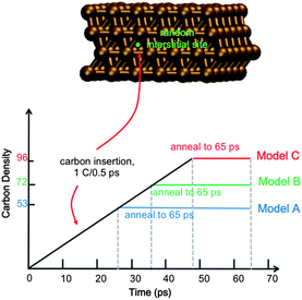
Full details of the QM/MD methodology are included in the ESI.† All simulations reported here employ a model 4-layer Ni(111) surface consisting of 144 Ni atoms (Fig. 1). The bottom Ni layer was held stationary throughout, thereby approximating the underlying bulk region. Carbon dissolution was simulated by adding carbon atoms into randomly selected interstitial sites in the Ni(111) subsurface at intervals of 0.5 ps, as done previously.14 We note here that this approach precludes a study of the mechanism of carbon dissolution itself, since our MD timescales are too short for this process. Xu et al.18 have previously shown that surface → subsurface diffusion (into subsurface octahedral sites) in Ni catalysts is thermodynamically favorable, and it is therefore not necessary to include this process in the context of graphene nucleation. On-surface chemisorption becomes increasingly favorable at higher subsurface carbon densities, thereby driving the reverse precipitation process. To establish the role of carbon density in SLG versus MLG growth, we simulate graphene growth using three different subsurface carbon densities, viz. ∼37, 50 and 66 atom% (denoted as trajectories An, Bn, and Cn, where n = 1, 2, …, 10 reflects the 10 trajectories computed for each density). These densities correspond to 74, 100 and 133% of the carbon required to form continuous SLG for a model system of this size. We note here that experimentally observed carbon densities are much lower than these values (on the order of 0.15 atom% (ref. 16)); however these data represent a statistical sample over a relatively large catalyst surface area, and do not preclude highly localized regions of high carbon density. Indeed, a high, localized carbon density may be required initially for graphene formation, as it is for fullerene and carbon nanotube formation.19,20
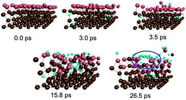
Fig. 2 depicts graphene nucleation observed using the lowest carbon density (trajectory A1). This trajectory is also shown in Movie M1 (ESI†). Graphene nucleation in this case was induced by free diffusion of carbon atoms and small Cn moieties between interstitial sites within the Ni(111) subsurface. A larger carbon cluster formed quickly in the Ni(111) subsurface as a result of this subsurface diffusion, despite the geometrical confinement induced by the Ni(111) lattice, and this was driven by the relative strengths of the Ni–C and C–C bonds.21 Confinement of these subsurface clusters resulted however in an amorphous structure (as evidenced by comparing the populations of sp, sp2 and sp3 carbon atoms in Fig. S4†), as opposed to one dominated by planar sp2 hybridized carbon. Precipitation of the cluster from the subsurface to the Ni(111) surface led to its immediate transformation into one predominantly composed of hexagons. It is noted that graphene nucleation observed in this simulation is essentially the same as that reported by us previously.14 This is not surprising, since the only difference between these simulations is the topology of the Ni(111) surface (pristine terrace versus a model step-edge defect), and these subsurface dynamics are naturally independent of surface structure. We also note that the propensity towards polyyne chain formation on the catalyst surface is consistent with recent graphene growth intermediates observed in TEM experiments.22
 | ||
| Fig. 2 Sub-surface nucleation of single-layer graphene (trajectory A1) at a carbon density of 37 atom%. | ||
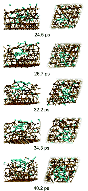
Precipitation of the cluster onto the catalyst surface caused significant disruption and expansion of the Ni(111) structure. While this malleability of the Ni(111) structure is a direct consequence of the presence of intercalated carbon atoms/clusters within its subsurface, it nonetheless promotes the diffusion and precipitation of these species. This therefore suggests that the surface mobility of atoms within the catalyst structure is a key ingredient in graphene formation itself. A direct consequence of this mobility is the almost instantaneous formation of step-edge defects in the originally crystalline Ni(111) structure following the precipitation of the graphene precursor structures. This step-edge self-assembly phenomenon bears strong resemblance to the inverse templating effect observed by Balbuena and co-workers during carbon nanotube cap nucleation on metal particles.23 No such step-edge formation was observed in our recent simulations that employed a catalyst surface with an a priori model step-edge defect. The present simulations therefore demonstrate that in the absence of a step-edge defect, the nucleating graphene precursor will alter catalyst morphology in order to form one. Step-edge self-assembly will become energetically favorable if the crystalline catalyst structure is first disrupted enough, as is the case in the presence of subsurface carbon.
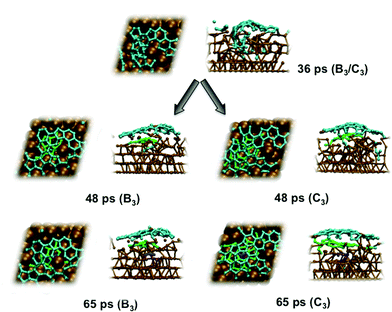
An explicit example of catalyst step-edge self-assembly is shown in Fig. 3. Step-edge defect formation itself was driven by the precursor needing to stabilize itself on the catalyst surface. This cannot take place solely through the relatively weak interaction between π (precursor) and d (catalyst) states. Instead, the catalyst is deformed in favor of the formation of stronger terminal Ni–C σ-bonds. This phenomenon explains the apparent positive curvature of graphene precursors observed experimentally,24 and is apparently independent of the catalyst identity.13 Once the precursor precipitated to the catalyst surface, the precursor–catalyst interface was never static; the newly formed step-edge defect moved and reorganized according to the diffusion and growth of the precursor structure. The perturbation to the catalyst surface was localized; as shown in Fig. 3, the lower layers of the Ni(111) surface exhibited relatively crystalline features. This localization allowed the catalyst surface to ‘heal’ itself back into its original (111) structure over longer timescales. On this basis, it is concluded that catalyst structure cannot be exploited towards controlling the structural quality of graphene, at least in the case of nickel catalysts. Instead, the structure of the catalyst is dictated and controlled by the nucleating and growing graphene sheet.
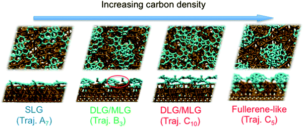
Previous experiments7 have shown that 1–2 layer graphene can be formed exclusively by careful control of the ambient feedstock pressure and rate of substrate cooling. By varying the carbon density in our model systems, we are able to elucidate this relationship between carbon density and SLG versus MLG formation. Fig. 4 (and Fig. S2 and 3†) shows that subsurface carbon densities of 50 atom% or greater result in the formation of MLG precursors. The structural confinement provided by the catalyst subsurface was once again a critical factor during this process. In essence, it impeded the precipitation of the first layer, and simultaneously promoted the formation of the second layer underneath it. The nucleation/precipitation mechanism of each graphene layer was essentially similar to that of SLG formation observed using a lower carbon density (Fig. 2). However, higher carbon density increased the rate of precipitation from the Ni(111) surface (Fig. S4–6†). Presumably, holding the carbon density at this value over longer timescales would result in further formation of graphene layers via this mechanism. However, using a carbon density of 66 atom% also results in the formation of structures resembling fullerenes, i.e. structures with high positive curvature, on the Ni(111) surface (Fig. 5). Considering the fact that this carbon density is 133% of that required to form an epitaxial graphene monolayer, it is likely that such a structure would be converted into an amorphous carbon structure, as opposed to graphene.
These simulations indicate that controlling subsurface carbon density can enable preferential formation of SLG over MLG. In particular, they indicate that MLG is the result of high subsurface carbon density in the Ni catalyst. Such a proposal is in line with an argument based upon bulk carbon solubility, and the fact that double-layer graphene (DLG) and MLG are not easily formed using Cu foils.25
Conclusions
In conclusion, our QM/MD simulations demonstrate that catalyst step-edge defect self-assembly results naturally from the presence of subsurface carbon during graphene formation. In the absence of a step-edge defect, the graphene precursor will actively transform the catalyst surface to form one. This step-edge formation is made possible by the malleability of the Ni catalyst surface itself. Furthermore, our simulations indicate that the density of subsurface carbon determines whether SLG or MLG forms. Confinement of high carbon densities within the catalyst subsurface leads to the formation of MLG by an identical mechanism to that of SLG formation. Controlling subsurface carbon density may therefore enable the preferential formation of SLG, instead of MLG. This is consistent with experimental reports that SLG and DLG formation can be tuned through the careful control of feedstock pressure, and the substrate cooling rate during CVD graphene synthesis.7Acknowledgements
The authors wish to thank Prof. Stephan Hofmann, University of Cambridge, for informative discussions. This work was in part supported by a CREST fund from JST. Y. W. acknowledges the support of the National Youth Fund (no. 21203174) and Jilin Province Youth Fund (no. 20130522141JH). A. J. P. acknowledges a Fukui Fellowship from Kyoto University and a University Fellowship from The University of Newcastle.Notes and references
- A. K. Geim and K. S. Novoselov, Nat. Mater., 2007, 6, 183–191 CrossRef CAS PubMed
.
- F. Schwierz, Nat. Nanotechnol., 2010, 5, 487–496 CrossRef CAS PubMed
.
- A. K. Geim, Science, 2009, 324, 1530–1534 CrossRef CAS PubMed
.
- M. Batzill, Surf. Sci. Rep., 2012, 67, 83–115 CrossRef CAS PubMed
.
- N. C. Bartelt and K. F. McCarty, MRS Bull., 2012, 37, 1158–1165 CrossRef CAS
.
- R. Addou, A. Dahal, P. Sutter and M. Batzill, Appl. Phys. Lett., 2012, 100, 021601–021603 CrossRef
.
- A. Reina, S. Thiele, X. Jia, S. Bhaviripudi, M. Dresselhaus, J. Schaefer and J. Kong, Nano Res., 2009, 2, 509–516 CrossRef CAS
.
- Q. Yuan, J. Gao, H. Shu, J. Zhao, X. Chen and F. Ding, J. Am. Chem. Soc., 2011, 134, 2970–2975 CrossRef PubMed
.
- Y. Wang, A. J. Page, Y. Nishimoto, H.-J. Qian, K. Morokuma and S. Irle, J. Am. Chem. Soc., 2011, 133, 18837–18842 CrossRef CAS PubMed
.
- W. Zhang, P. Wu, Z. Li and J. Yang, J. Phys. Chem. C, 2011, 115, 17782–17787 CAS
.
- D. Cheng, G. Barcaro, J. C. Charlier, M. Hou and A. Fortunelli, J. Phys. Chem. C, 2011, 115, 10537–10543 CAS
.
- J. Gao, Q. Yuan, H. Hu, J. Zhao and F. Ding, J. Phys. Chem. C, 2011, 115, 17695–17703 CAS
.
- A. J. Page, Y. Wang, H.-B. Li, S. Irle and K. Morokuma, J. Phys. Chem. C, 2013, 117(28), 14858–14864 CAS
.
- H.-B. Li, A. J. Page, Y. Wang, S. Irle and K. Morokuma, Chem. Commun., 2012, 48, 7937–7939 RSC
.
- X. Tang, Z. Xie, T. Yin, J.-W. Wang, P. Yang and Q. Huang, Phys. Chem. Chem. Phys., 2013, 15, 16314–16320 RSC
.
- R. S. Weatherup, B. C. Bayer, R. Blume, C. Ducati, C. Baehtz, R. Schlögl and S. Hofmann, Nano Lett., 2011, 11, 4154–4160 CrossRef CAS PubMed
.
- J. Gao, J. Yip, J. Zhao, B. I. Yakobson and F. Ding, J. Am. Chem. Soc., 2011, 133, 5009–5015 CrossRef CAS PubMed
.
- J. Xu and M. Saeys, J. Phys. Chem. C, 2008, 112, 9679–9685 CAS
.
- S. Irle, G. Zheng, Z. Wang and K. Morokuma, J. Phys. Chem. B, 2006, 110, 14531–14545 CrossRef CAS PubMed
.
- A. J. Page, Y. Ohta, S. Irle and K. Morokuma, Acc. Chem. Res., 2010, 43, 1375–1385 CrossRef CAS PubMed
.
- A. J. Page, H. Yamane, Y. Ohta, S. Irle and K. Morokuma, J. Am. Chem. Soc., 2010, 132, 15699–15707 CrossRef CAS PubMed
.
- T. Niu, M. Zhou, J. Zhang, Y. Feng and W. Chen, J. Am. Chem. Soc., 2013, 135, 8409–8414 CrossRef CAS PubMed
.
- D. A. Gómez-Gualdrón, G. D. McKenzie, J. F. J. Alvarado and P. B. Balbuena, ACS Nano, 2011, 6, 720–735 CrossRef PubMed
.
- P. Lacovig, M. Pozzo, D. Alfe, A. Baraldi and S. Lizzit, Phys. Rev. Lett., 2009, 103, 166101-1 Search PubMed
.
- C.-M. Sung and M.-F. Tai, Int. J. Refract. Met. Hard Mater., 1997, 15, 237–256 CrossRef CAS
.
Footnotes |
| † Electronic supplementary information (ESI) available: Full details of the QM/MD methodology and final snapshots, carbon spn-hybridization populations, polygonal carbon ring populations and carbon cluster sizes for models A, B and C, and a QuickTime movie file of trajectory A1. See DOI: 10.1039/c3nr04694j |
| ‡ These authors contributed equally. |
| This journal is © The Royal Society of Chemistry 2014 |

