Effect of microstructure and Sn/C ratio in SnO2–graphene nanocomposites for lithium-ion battery performance
Mahbuba Ara,
Kapila Wadumesthrige,
Tiejun Meng,
Steven O. Salley and
K. Y. Simon Ng*
Department of Chemical Engineering and Materials Science, Wayne State University, Detroit, MI 48202, USA. E-mail: sng@wayne.edu; Fax: +1 313 577 8171; Tel: +1 313 577 3805
First published on 22nd April 2014
Abstract
Sn based nanocomposite anodes with a pristine graphene matrix were synthesized in order to investigate the performance improvements that are related to the microstructure variation. Four nanocomposites with varying SnO2 contents (25, 43, 60, and 82 wt%) were prepared with a controlled hydrothermal synthesis route. TEM measurements indicated that the 25/75 wt% SnO2–graphene nanocomposite had the highest dispersivity with a 2–3 nm particle size and ∼2 nm inter-particle spacing. Increasing SnO2 content led to increasing particle size and decreasing inter-particle spacing. For the anode with more dispersed and smaller nanoparticles, the capacity retention and rate capability were noticeably improved compared with anodes that have clusters of SnO2 nanoparticles. The 25/75 wt% SnO2–graphene nanocomposite exhibited enhanced specific capacity of 662 mA h g−1 after 150 cycles when discharged–charged at 50 mA g−1. It also demonstrated an outstanding rate capability of 525, 445 and 230 mA h g−1 at higher current densities of 300, 500 and 1000 mA g−1, respectively. TEM and EIS studies revealed that after 100 electrochemical cycles, the nanoparticles retained the original size of 2–3 nm and cell's charge transfer resistance decreased by 52%.
1. Introduction
While rechargeable lithium-ion batteries are the predominant power sources for portable electronic devices, more advanced lithium-ion batteries with high energy and power density, rate capability and excellent cycling stability are required to achieve economically-competitive electric vehicles. Commercial lithium-ion batteries are usually based on carbonaceous anode materials, like graphite, which do not exhibit the problem of dendrite formation experienced in the initially employed lithium metal anode.1,2 However, graphite displays a low theoretical charge capacity (372 mA h g−1) and a low practical energy density.3,4 Moreover, the chemical diffusion coefficient of the lithium ion is always less than 10−6 cm2 s−1 in a graphite anode, which results in a low power density of the battery.5Sn and Si have achieved much attention for their respective high theoretical capacities of 994 mA h g−1 and 4200 mA h g−1. Compared to Si-based materials, SnO2-based materials have advantages of lower price and easier processing for lithium-ion battery anodes.6 However, both Sn and Si undergo significant volume expansion upon Li-insertion, which can be as high as 300%.7 The volume expansion/contraction can result in cracking, which in turn leads to active material which is no longer in electrical contact with the remainder of the electrode and resultant poor cycle life and capacity fading.
Consequently, various efforts have been devoted to eliminate such a problem by applying different morphological schemes, example of which include, SnO2 nanorods,8 nanowires,9,10 nanobelts,11,12 nanotubes,13,14 hollow spheres15,16 and mesoporous structures.17 The utilization of nanoparticles18,19 seems to be a promising route to lessen the pulverization problem because it can reduce absolute local volume changes and also the diffusion path of lithium ions. Another option is to introduce a suitable matrix, such as graphene,20–23 TiO2 nanofibers,24 carbon nanofibers,25 etc., to accommodate the volume change and to dissipate the local mechanical stress on SnO2 nanoparticles.
Graphene, a single layer of carbon atoms arranged in a 2D honeycomb lattice, has superior electrical conductivity and a high surface area of over 2600 m2 g−1.26,27 As such, chemically reduced graphene oxide (rGO) has been investigated as a 2D conductive template on which SnO2 nanoparticles are decorated to build a 3D interconnected porous network to improve the mechanical stability and Li+ ions storage capacity.20–23 Paek et al.20 reported a charge capacity of 570 mA h g−1 at a current density of 100 mA g−1 after 30 cycles for SnO2–graphene anode material prepared by the physical mixing of graphene nanosheets and SnO2 nanoparticles. Zhu et al.22 reported a discharge capacity of 649 mA h g−1 after 30 cycles at a current density of 50 mA g−1 for SnO2–graphene, where the sample was prepared by a co-precipitation method. Long cycle life with superior charge–discharge capacities and rate capability of the SnO2–graphene nanocomposites were not reported. Failure of these anode materials can be attributed to the inadequate dispersion of the SnO2 nanoparticles on the graphene support. Most recently, Dimitrijevic et al. demonstrated theoretically that inter-particle spacing is an important design criterion for higher mechanical stability.28 It was supported by experimental works29,30 relating to void spaces acting as a buffer region for particle expansion. No report has been published on the evaluation of various microstructural changes based on SnO2 content in the nanocomposite anode. An improved microstructure with highly dispersed nanoparticles may minimize volume expansion stress and avoid anode fracture. Moreover, SnO2 nanoparticles tend to agglomerate with prolonged cycling which inevitably reduce the lithium storage capability as a result of hindered Li+ ion diffusion and formation of unstable SEI.31 Therefore, properly designed anode architecture should be developed to minimize the aggregation of particles while keeping the electrode components highly conductive and active for electrochemical performance.
The present study is a systematic investigation of four different levels of SnO2 content, i.e. 25, 43, 60, and 82 wt%, with various particle distributions on graphene support matrix. Correlation between the Li-ion cell performances and Sn/C ratio and microstructure of the SnO2–graphene nanocomposites is investigated. The particle size and the corresponding inter-particle spacing were evaluated by transmission electron microscope imaging technique before and after cycling. The electrochemical performances were examined using multiple current density cycles.
2. Experimental
2.1. Materials
SnCl4·5H2O (Tin(IV) chloride pentahydrate, Sigma-Aldrich, 98%), NaOH (Mallinckrodt Chemical Inc.), nano graphene platelet (N006-P, Angstron Materials Inc.), ethyl alcohol (Mallinckrodt Chemical Inc.) and Ar gas (ultra high purity grade, 99.99% Ar from Metro Welding Supply Corp.) were used as received without further purification.2.2. Preparation of SnO2–graphene nanocomposites
SnO2 nanoparticles were synthesized by sol–gel method using SnCl4·5H2O32 as a precursor. 75 mL of a 0.1 M NaOH aqueous solution was added at a rate of 1 mL min−1 to an aqueous solution of SnCl4·5H2O (0.05 M, 150 mL) under vigorous stirring. The resultant light white solution was sonicated (Branson 2510, 100 W) for 10 min. At the same time, two hundred mg of graphene nanoplatelets was mixed with ethylene glycol using an ultrasonic probe (Microson XL-2000, QSonica, LLC, 100 W) to make a dispersion with a concentration of 1 mg mL−1. The dispersed graphene was added to the light white solution and stirred for three hours. The resulting solution was then centrifuged at 3000 rpm (Eppendorf International, Centrifuge 5804R) to collect the precipitate. The precipitate was washed with DI water and ethanol sequentially until the pH of the filtrate was close to 7. The solid product was dried under vacuum and heat treated at 400 °C for 2 h in an Ar atmosphere. Four different concentrations of SnO2 in SnO2–graphene, i.e., 25, 43, 60, and 82 wt%, were prepared.2.3. Materials characterization
Transmission electron microscopy (TEM) images were obtained using a JEOL JEM-2010 microscope. The samples were prepared by the dispersion of the materials in ethanol using sonication and drop-casting onto carbon-coated TEM grids and dried in air. Length of the particle diameter and the inter-particle distances were measured using AMT-600 from Advanced Microscopy Techniques Corp. A line connecting to the desired end points could give the linear measurement with a corresponding label. The morphology of these samples was also examined by scanning electron microscopy (SEM) using a JEOL JSM-7600F. Powder X-ray diffraction (XRD) was performed using a Rigaku SmartLab high resolution θ/2θ XRD system with a graphite monochromator with Cu Kα radiation (λ = 1.5406 Å). Scattering angles (2θ) of 5–80° at a scanning rate of 3° min−1 was used. Thermogravimetric analysis (TGA) was conducted with a thermal gravimetric analyzer (TGA, Perkin Elmer Pyris-1) from 25 to 1000 °C at a rate of 10 °C min−1 under controlled airflow. The carbonaceous sample was burned in a TG furnace and the residue was Sn(IV) oxide.2.4. Electrochemical tests
To fabricate an electrode, sample powder (SnO2–graphene) was mixed with 10 wt% conductive carbon (CNERGY Super C65, Timcal Graphite & Carbon) and pressed onto an expanded Cu microgrid (2Cu6-077F, Dexmet Corporation). The material was then assembled into test cells (#2032 coin cell) using lithium-metal foil as the negative electrode, a micro porous polypropylene separator (Celgard 2320), and an electrolyte of 1 M LiPF6 in a 1![[thin space (1/6-em)]](https://www.rsc.org/images/entities/char_2009.gif) :1 (w/w) mixture of ethylene carbonate (EC) and dimethyl carbonate (DMC). Cells were assembled inside an argon filled glove box where both the moisture and oxygen content were below 1 ppm. All cells were tested at a constant current density of 100 mA g−1 between fixed voltage limits of 2 V to 0.01 V using a Maccor series 4200 battery tester. Moreover, the 25 wt% SnO2–graphene sample was tested at 50 mA g−1 current density in a cycling test. The current density and electrode capacities were calculated based on the total mass of SnO2 and graphene. Electrochemical impedance spectroscopy measurement was performed using a Gamry Reference 3000 from 1 MHz to 0.01 Hz at 3.5 mV rms.
:1 (w/w) mixture of ethylene carbonate (EC) and dimethyl carbonate (DMC). Cells were assembled inside an argon filled glove box where both the moisture and oxygen content were below 1 ppm. All cells were tested at a constant current density of 100 mA g−1 between fixed voltage limits of 2 V to 0.01 V using a Maccor series 4200 battery tester. Moreover, the 25 wt% SnO2–graphene sample was tested at 50 mA g−1 current density in a cycling test. The current density and electrode capacities were calculated based on the total mass of SnO2 and graphene. Electrochemical impedance spectroscopy measurement was performed using a Gamry Reference 3000 from 1 MHz to 0.01 Hz at 3.5 mV rms.
3. Results and discussion
3.1. TGA analysis
TGA was performed in air, in order to quantify the amount of SnO2 in the nanocomposites. Fig. 1 shows the TGA profiles of different nanocomposite samples along with pristine graphene and bare graphite (for comparison). SnO2 mass percent is determined to be about 82, 60, 43, and 25% respectively in four different samples of SnO2–graphene nanocomposites. The pristine graphene and graphite had the greatest weight loss at 620 °C and 710 °C, respectively, and the composites were stable until 680 °C. These results are consistent with previous reports.33–35 Weight loss of graphene at a temperature as low as 200 °C is attributed to pyrolysis of the labile oxygen-containing functional groups such as OH, COOH, etc.36 However, this low temperature weight loss was not observed for SnO2–graphene materials because these functional groups were removed during the nanocomposite synthesis process.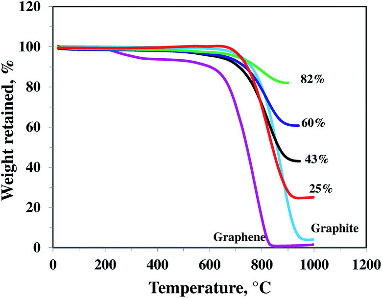 | ||
| Fig. 1 TGA curves of different SnO2–graphene composite with 82, 60, 43, and 25 wt% SnO2, pristine graphene nanosheets and graphite. | ||
3.2. Microstructure characterization
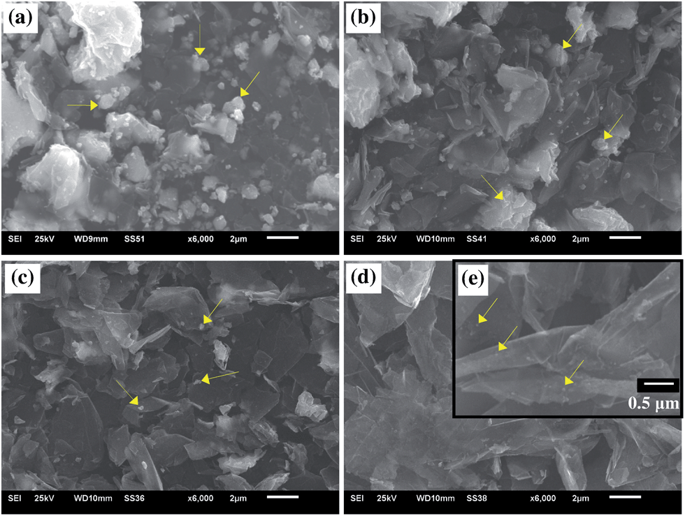 | ||
| Fig. 2 SEM images of (a) 82, (b) 60, (c) 43, and (d) lower magnification and (e) higher magnification of 25 wt% SnO2 concentrations in SnO2–graphene composites. | ||
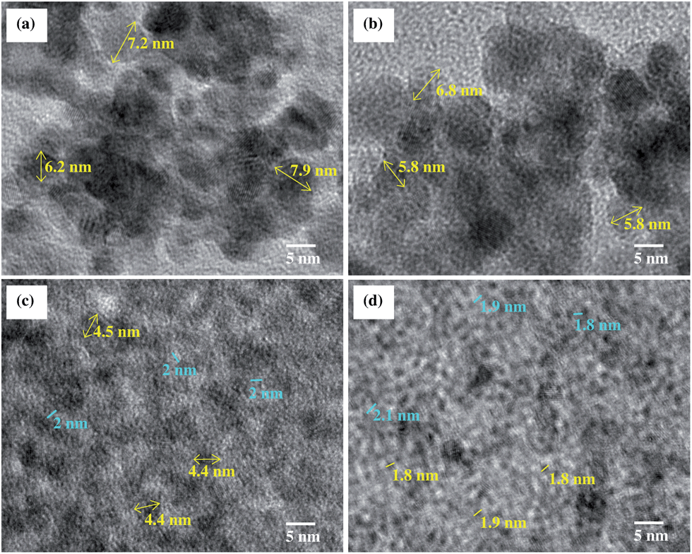 | ||
| Fig. 3 TEM images of SnO2–graphene composite with (a) 82, (b) 60, (c) 43, and (d) 25 wt% SnO2. Yellow lines are indicating the length of the nanoparticles and aqua colored lines are the measurement of inter-particle distances. | ||
cosθ), where λ is the X-ray wavelength, β is the full width at half maximum intensity, and θ is the angle corresponding to the peak. Using the Scherrer equation for the (101) peak (2θ = 34°), the sizes of SnO2 crystals in the 25, 43, 60, and 82 wt% SnO2 are 4, 8, 11, and 12 nm, respectively. Average particle sizes were calculated based on Scherrer equation which includes contributions from grains and agglomerates. Hence, from the TEM images and the XRD patterns, the individual particle sizes are around 2–3, 4–8, 6–11, and 7–12 nm for 25, 43, 60, and 82 wt% composites, respectively. The larger SnO2 nanoparticles with higher Sn/C ratios are attributed to the higher initial Sn4+ ion concentrations in the precursors.38 The major diffraction peak is at ∼27° (002) for graphene platelets which is located in the same peak position of SnO2 (110) in the SnO2–graphene nanocomposites.
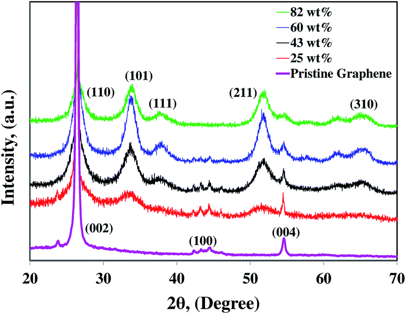 | ||
| Fig. 4 XRD pattern of the SnO2–graphene nanocomposite for 82, 60, 43, and 25 wt% SnO2 and pristine graphene nanosheets. | ||
3.3. Electrochemical characterization
To evaluate the storage capacity and cyclability, the 25, 43, 60, and 82 wt% SnO2–graphene nanocomposites were used as cathodes for lithium ion half-cell configurations with respect to ‘Li’ as anodes. Fig. 5(a) shows the galvanostatic first cycle charge–discharge profiles for the anodes measured at a current density of 100 mA g−1 and cutoff voltage range of 0.01 V to 2.0 V. In the first discharging (Li insertion) process, all samples show plateau at around 1.0–0.8 V, which is also observed for the graphene anode. The plateau can be attributed to the formation of solid-electrolyte interface (SEI) and Li2O and Sn according to the reaction: SnO2 + 4Li → Sn + 2Li2O.39 This plateau becomes progressively smaller when the loading of SnO2 decreased from 82 to 25 wt%, indicating that Li2O is formed in smaller quantities as a result of lower loading of SnO2 in the nanocomposites. This plateau nearly disappeared from the second cycle for only the 25 wt% sample, which suggests that there is lower first cycles irreversible capacity losses with well dispersed SnO2 nanoparticles in the nanocomposite. For charge cycles, the SnO2–graphene nanocomposites showed a plateau at around 0.5 V due to the reaction: LixSn ↔ Sn + xLi+ + xe− (0 ≤ x ≤ 4.4) with the maximum 4.4 Li insertion for one Sn for the formation of Li22Sn5 alloy.40,41 Lithium can intercalate with graphite according to the reaction: Li+ + 6C + e− ↔ LiC6.42 The lithium intercalation/deintercalation potential in the graphene layers of graphite is ∼0.2–0.1 V.43 The potential plateaus at around ∼0.1 V become progressively larger with the lower SnO2 content in the composites. This observation implies that the synergistic effect of both SnO2 and pristine graphene is enhanced with proper morphology of SnO2 nanoparticles and good dispersion on the graphene sheets.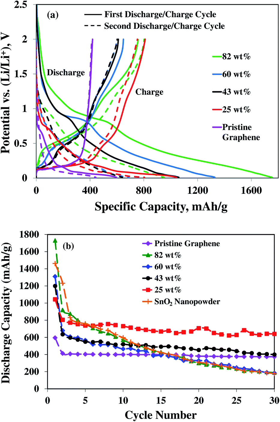 | ||
| Fig. 5 (a) Galvanostatic charge–discharge profile for first and second (dotted line) cycle and (b) cyclic performance at a current density of 100 mA g−1 for the samples of 82, 60, 43, and 25 wt% SnO2 in the composites, SnO2 nanopowders, and pristine graphene nanosheets. | ||
A comparative study of specific capacities with cycling of four nanocomposites, pure SnO2 nanopowder and pristine graphene are shown in Fig. 5(b). In the first cycle at a current density of 100 mA g−1, the anode materials deliver the lithium insertion capacity (the discharge cycle) of 1730, 1310, 1200, 1044, 595, and 1461 mA h g−1 for the 82, 60, 43, 25 wt% SnO2–graphene nanocomposites, pristine graphene, and pure SnO2 nanopowder, respectively. Theoretical capacity of SnO2 for the first cycle lithium insertion process is 1494 mA h g−1.22,39 It is well-known that in the initial cycle, the irreversible capacities of lithium ion batteries are mainly caused by the formation of solid electrolyte interphase (SEI) films, as a result of the irreversible reactions of lithium ions with electrolyte species. SEI films have the permeability for lithium ions and protect the electrode surface from further reactions with electrolytes.39,44 The first cycle irreversible reaction to form Sn and Li2O from Li+ and SnO2 is also responsible for the capacity loss.40,41 After 30 cycles, pure SnO2 nanopowder electrode (Fig. 5(b)) exhibits a rapidly decayed discharge capacity of 178 mA h g−1 (12% retention of the initial capacity), whereas pristine graphene exhibits stable capacity of 375 mA h g−1 (63% retention of the initial capacity). The main reason of rapid capacity fading for pure SnO2 nanoparticles is the large volume expansion of Sn during alloying reaction with lithium, leading to pulverization of the electrode.21,23 The 82 wt% composite exhibited similar trend of early cycle decay as the pure SnO2 nanoparticles. Though the 60 wt% composite exhibits better capacity retention in the early cycles, after 30 cycles the capacity retention is very low (only 183 mA h g−1, 14% of initial capacity). Based on the results for the pristine graphene and pure SnO2 electrodes, the cycling instability is attributed to the diminishing electrochemical activity of the Sn particles. Hence, graphene matrix alone cannot provide sufficient stabilizing effect to the composites with higher Sn content.
For the 43 wt% composite, an improvement to the capacity retention is observed compared to 60 and 82 wt% composites, with a reversible capacity of 400 mA h g−1 and slower fading rate of 1.1% after 30 cycles, compared to 5.2 and 4.1% for 82 and 60 wt% composites, respectively. This improvement of cycling stability with higher capacity is likely due to the smaller size and better dispersion of nanoparticles on the graphene sheets. However, the average inter-particle distance is about 2.2 nm for these 4–8 nm diameter SnO2 particles, which still cannot provide the sufficient spacing and dispersion for good structural stability with cycling.
Further improvement of the capacity retention is observed for the 25 wt% SnO2 composite (Fig. 5 and 6). The discharge capacity is 662 mA h g−1 after 150 cycles and 640 mA h g−1 after 30 cycles at 50 and 100 mA g−1 current densities, respectively. The theoretical capacity of 25 wt% SnO2–graphene was calculated to be 753.5 mA h g−1 based on the theoretical capacity of SnO2 (782 mA h g−1) and pristine graphene (744 mA h g−1).45 The observed capacities of 25 wt% SnO2–graphene are comparable to the theoretical capacity, suggesting that there are synergistic effects to improve cyclic performance. This distinct performance can be attributed to the microstructure optimization of the composite. SEM and TEM images (Fig. 2 and 3) reveal that graphene sheets are well-separated and SnO2 nanoparticles are highly dispersed on the matrix. The average diameter of SnO2 nanoparticle is around 2–3 nm with ∼2 nm inter-particle spacing. With this particle size and spacing, SnO2 nanoparticles can react with lithium without developing excessive internal stress and form a stable SEI layer on the surface of the particles.46,47 Better dispersion can lead to the less re-stacking of the graphene nanosheets with cycling which can act as a better lithium storage electrodes.21,23 Furthermore, well-dispersion can enhance the benefits of conductive graphene network in the electrode. Hence, well-distributed nanoparticles on graphene should exhibit stronger synergistic effects of both graphene and Sn nanoparticles with enhanced capacity retentions. Although at 50 mA h g−1 current density, the 25 wt% composite shows higher discharge capacity 662 mA h g−1 after 150 cycles with high coulombic efficiency of 95%, a slow capacity fading with cycling is still evident as seen in Fig. 6(a). This suggested that at this smaller current density, 2 nm sized particles with very high surface area can increase the surface interactions with the electrolyte; such instances may result in the unwanted side reactions, forming an insulating and Li+ impeding layers, which may affect the corresponding anode cyclic performances.48,49
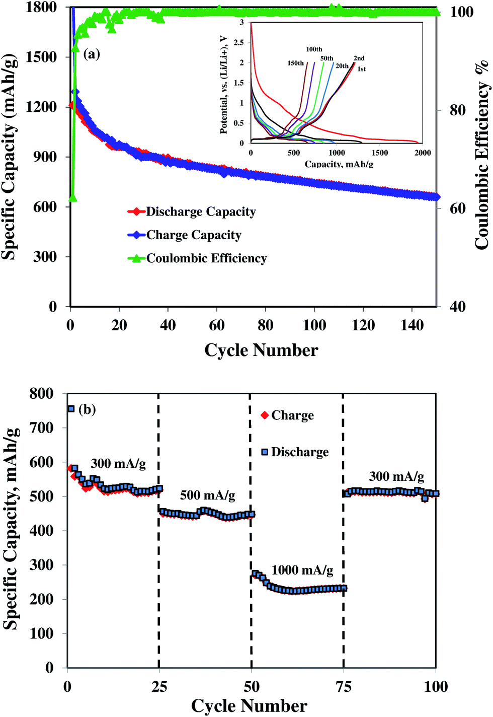 | ||
| Fig. 6 (a) Galvanostatic charge–discharge profile for different cycles in inset and cyclic performance at a current density of 50 mA g−1, (b) rate capability study of 25 wt% SnO2–graphene nanocomposite. | ||
To further elucidate the effects of microstructural improvement to the electrochemical performance of the 25 wt% SnO2–graphene electrode, the rate capabilities were evaluated at different current densities, as shown in Fig. 6(b). The discharge capacity of the 25 wt% SnO2–graphene electrode decreases as the current density increases, and the electrode shows a stable specific capacity of 525 mA h g−1 at a current density of 300 mA g−1 and 445 mA h g−1 at a current density of 500 mA g−1. These results are much more promising than the previous studies.20–23 When the current density reaches 1000 mA g−1, the capacity becomes stable at 230 mA h g−1. After cycling at high current densities, the cell is galvanostatically discharged–charged again at a current density of 300 mA g−1, and substantial capacity is recovered without noticeable capacity fading. This result indicates a fully preserved microstructure of the nanocomposite electrode after cycling even at higher current rates.
3.4. TEM observations after cycling
The TEM images in Fig. 7(a) and (b) show the 82 and 25 wt% SnO2–graphene nanocomposites in the de-lithiated condition after 100 charge–discharge cycles. Large Sn nanoclusters (>15 nm) on graphene nanosheets for the 82 wt% sample are evident, compared with around 7 nm before cycling (Fig. 3). This can be attributed to aggregation of Sn on the graphene nanosheets upon cycling. On the other hand, for the 25 wt% sample, Sn nanoparticles are well-spread out on the graphene sheets and retained a size of around 3 nm after cycling, which is comparable to the original particle size. Furthermore, in Fig. 7(a), larger and agglomerated Sn particles are pulverized to several nano- and micron-sized particles for 82 wt% loading, whereas, in Fig. 7(b), nano-sized particle distribution was observed for 25 wt% electrodes without any pulverization.30 Fig. 8 is the schematic representation of four SnO2–graphene composites before and after cycling. After cycling, the 82 wt% (Fig. 7(a)) composite has more agglomerated and larger particles than the 25 wt% (Fig. 7(b)) composite and micron-sized Sn-clusters are surrounded by nano-sized particles.18 The least particle expansion with stable inter-particle distances can be observed for the 25 wt% SnO2–graphene composite after the electrochemical cycles. | ||
| Fig. 7 TEM images of (a) 82 and (b) 25 wt% SnO2–graphene after 100 discharge–charge cycles. | ||
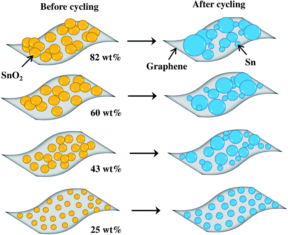 | ||
| Fig. 8 Schematic illustrations of 82, 60, 43, and 25 wt% SnO2–graphene nanocomposites before and after electrochemical cycling. | ||
3.5. Impedance spectroscopy analysis
Fig. 9 shows the AC impedance spectroscopy (EIS) for 25 and 82 wt% SnO2–graphene electrodes before cycling and after 100 cycles, along with the equivalent circuit model (inset). In these Nyquist plots, the intercept at the Z-real axis corresponds to the solution resistance (Rs), which represents uncompensated total resistance of the electrolyte, separator and electrical contacts. The diameter of the semicircle in the high to middle frequency region includes the superposition of the impacts of the surface films (resistance to Li+ ion migration) and the charge transfer resistance (Rct) coupled with the relevant double layer capacitance (constant phase element (CPE)).50 The inclined line at lower frequencies represents the Warburg impedance (W), which is associated with lithium ion diffusion in the SnO2–graphene nanoparticles. There is very little difference among the Rs values (6–14 Ω) of all four composites before and after cycling. Rct values are listed in Table 1 for the composites at different cycles. It can be seen that there is an increase in the value of Rct with cycling for 82 and 60 wt% composites, which can be attributed to the increase in the inter-particle contact resistance induced by continuous SEI formation on the particles during cycling.50 Moreover, the increase in Rct as wt% of SnO2 increases could be due to the higher degree of agglomeration and lack of homogeneity in the electrode resulting in poor electric contact.51 On the other hand, for the 43 and 25 wt% composites, Rct values decrease with cycling which can be mainly ascribed to an enhanced electron and Li+ ion transport for well-dispersed SnO2 nanoparticles on the graphene sheets which facilitates a stable passive layer formation on the nanoparticles.35 The higher graphene content with the same amount of carbon black could increase the conductivity resulting in the lower Rct.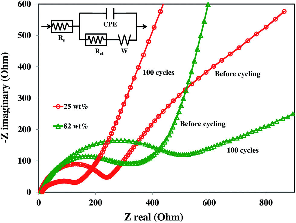 | ||
| Fig. 9 Nyquist plots of 82 and 25 wt% SnO2–graphene anodes before and after 100 discharge–charge cycles. | ||
| SnO2–graphene electrodes | Rct (Ω) | |
|---|---|---|
| Before cycling | After 100 cycles | |
| 82 wt% | 316 | 498 |
| 60 wt% | 250 | 394 |
| 43 wt% | 230 | 132 |
| 25 wt% | 240 | 126 |
4. Conclusions
The Sn/C ratio and microstructure of SnO2–graphene nanocomposite anode can dramatically affect the electrochemical properties of Li-ion batteries. Optimized anode structure was obtained for 25/75 wt% SnO2–graphene composite containing 2–3 nm SnO2 nanoparticles with ∼2 nm inter-particle distance, which noticeably enhanced the electrochemical properties of SnO2–graphene composite anodes. The excellent discharge capacity retention and rate capability of 25/75 wt% SnO2–graphene composite compared to higher Sn contents may be attributed to: (i) optimal particle size (ii) well-distributed nanoparticles with good inter-particle distance, (iii) formation of stable electrode–electrolyte interface during cycling, and (iv) increased synergistic effects of both graphene and SnO2.Acknowledgements
Financial support from the Department of Energy (Grant DE-EE0002106) for this research is gratefully acknowledged.References
- H. Buqa, D. Goers, M. Holzapfel, M. E. Spahr and P. Novak, J. Electrochem. Soc., 2005, 152, A474 CrossRef CAS PubMed.
- Y. P. Wu, E. Rahm and R. Holze, J. Power Sources, 2003, 114, 228 CrossRef CAS.
- J. R. Dahn, Z. Tao, Y. Liu and J. S. Xue, Science, 1995, 270, 590 CAS.
- K. Sato, M. Noguchi, A. Demachi, N. Oki and M. Endo, Science, 1994, 264, 556 CAS.
- K. Persson, V. A. Sethuraman, L. J. Hardwick, Y. Hinuma, Y. S. Meng, A. V. D. Ven, V. Srinivasan, R. Kostecki and G. Ceder, J. Phys. Chem. Lett., 2010, 1, 1176 CrossRef CAS.
- A. R. Kamali and D. J. Fray, Rev. Adv. Mater. Sci., 2011, 27, 14 CAS.
- L. Y. Beaulieu, K. W. Eberman, R. L. Turner, L. J. Krause and J. R. Dahn, Electrochem. Solid-State Lett., 2001, 4, A137 CrossRef CAS PubMed.
- X. Ji, X. Huang, J. Liu, J. Jiang, X. Li, R. Ding, Y. Hu, F. Wu and Q. Li, Nanoscale Res Lett., 2010, 5, 649 CrossRef CAS PubMed.
- P. Meduri, C. Pendyala, V. Kumar, G. U. Sumanasekera and M. K. Sunkara, Nano Lett., 2009, 9, 612 CrossRef CAS PubMed.
- M. Park, G. Wang, Y. Kang, D. Wexler, S. Dou and H. Liu, Angew. Chem., 2007, 119, 764 CrossRef.
- J. Hu, Y. Bando, Q. Liu and D. Golberg, Adv. Funct. Mater., 2003, 13, 493 CrossRef CAS.
- J. Duan, S. Yang, H. Liu, J. Gong, H. Huang, X. Zhao, R. Zhang and Y. Du, J. Am. Chem. Soc., 2005, 127, 6180 CrossRef CAS PubMed.
- J. Ye, H. Zhang, R. Yang, X. Li and L. Qi, small, 2010, 6, 296 CrossRef CAS PubMed.
- Y. Jia, L. He, Z. Guo, X. Chen, F. Meng, T. Luo, M. Li and J. Liu, J. Phys. Chem. C, 2009, 113, 9581 CAS.
- J. Yu, H. Guo, S. A. Davis and S. Mann, Adv. Funct. Mater., 2006, 16, 2035 CrossRef CAS.
- X. W. Lou, Y. Wang, C. Yuan, J. Y. Lee and L. A. Archer, Adv. Mater., 2006, 18, 2325 CrossRef CAS.
- X. Wang, Z. Li, Q. Li, C. Wang, A. Chen, Z. Zhang, R. Fan and L. Yin, CrystEngComm, 2013, 15, 3696 RSC.
- C. Kim, M. Noh, M. Choi, J. Cho and B. Park, Chem. Mater., 2005, 17, 3297 CrossRef CAS.
- J. Hassoun, G. Derrien, S. Panero and B. Scrosati, Adv. Mater., 2008, 20, 3169 CrossRef CAS.
- S. M. Paek, E. Yoo and I. Honma, Nano Lett., 2009, 9, 72 CrossRef CAS PubMed.
- J. Liang, W. Wei, D. Zhong, Q. Yang, D. L. Li and L. Guo, ACS Appl. Mater. Interfaces, 2012, 4, 454 CAS.
- X. Zhu, W. Y. Zhu, S. Murali, D. M. Stoller and S. R. Ruoff, J. Power Sources, 2011, 196, 6473 CrossRef CAS PubMed.
- H. Kim, W. S. Kim, U. Y. Park, H. Gwon, H. D. Seo, Y. Kim and K. Kang, Nano Res., 2010, 3, 813 CrossRef CAS PubMed.
- T. Tran, K. McCormac, J. Li, Z. Bi and J. Wu, Electrochim. Acta, 2014, 117, 68 CrossRef CAS PubMed.
- C. A. Bonino, L. Ji, Z. Lin, O. Toprakci, X. Zhang and S. A. Khan, ACS Appl. Mater. Interfaces, 2011, 3, 2534 CAS.
- Y. Hernandez, V. Nicolosi, M. Lotya, F. M. Blighe, Z. Sun, S. De, I. T. McGovern, B. Holland, M. Byrne, Y. K. Gun'Ko, J. J. Boland, P. Niraj, G. Duesberg, S. Krishnamurthy, R. Goodhue, J. Hutchison, V. Scardaci, A. C. Ferrari and J. N. Coleman, Nat. Nanotechnol., 2008, 3, 563 CrossRef CAS PubMed.
- F. Banhart and P. M. Ajayan, Nature, 1996, 382, 433 CrossRef CAS.
- B. J. Dimitrijevic, K. E. Aifantis and K. Hackl, J. Power Sources, 2012, 206, 343 CrossRef CAS PubMed.
- N. Liu, H. Wu, M. T. McDowell, Y. Yao, C. Wang and Y. Cui, Nano Lett., 2012, 12, 3315 CrossRef CAS PubMed.
- K. E. Aifantis, M. Haycock, P. Sanders and S. A. Hackney, Mater. Sci. Eng., A, 2011, 529, 55 CrossRef CAS PubMed.
- Q. Zhang, E. Uchaker, S. L. Candelaria and G. Cao, Chem. Soc. Rev., 2013, 42, 3127 RSC.
- L. Korosi, K. Mogyorosi, R. Kun, J. Nemeth and I. Dekany, Prog. Colloid Polym. Sci., 2004, 125, 27 Search PubMed.
- M. Wojtoniszak, X. Chen, R. J. Kalenczuk, A. Wajda, J. Łapczuk, M. Kurzewski, M. Drozdzik, P. K. Chu and E. Borowiak-Palen, Colloids Surf., B, 2012, 89, 79 CrossRef CAS PubMed.
- Y. Chen, H. Zhao, L. Sheng, L. Yu, K. An, J. Xu, Y. Ando and X. Zhao, Chem. Phys. Lett., 2012, 538, 72 CrossRef CAS PubMed.
- B. Wang, D. Su, J. Park, H. Ahn and G. Wang, Nanoscale Res. Lett., 2012, 7, 215 CrossRef CAS PubMed.
- S. Stankovich, D. A. Dikin, R. D. Piner, K. A. Kohlhaas, A. Kleinhammes, Y. Jia, Y. Wu, S. T. Nguyen and R. S. Ruoff, Carbon, 2007, 45, 1558 CrossRef CAS PubMed.
- K. E. Aifantis, S. A. Hackney and J. P. Dempsey, J. Power Sources, 2007, 165, 874 CrossRef CAS PubMed.
- E. Caue Ribeiro, J. H. Lee, T. R. Giraldi, E. Longo, J. A. Varela and E. R. Leite, J. Phys. Chem. B, 2004, 108, 15612 CrossRef.
- I. A. Courtney and J. R. Dahn, J. Electrochem. Soc., 1997, 144, 2045 CrossRef CAS PubMed.
- M. Winter, J. O. Besenhard, M. Spahr and P. Novak, Adv. Mater., 1998, 10, 725 CrossRef CAS.
- M. Winter and J. O. Besenhard, Electrochim. Acta, 1999, 45, 31 CrossRef CAS.
- K. Tatsumi, N. Iwashita, H. Sakaebe, H. Shioyama and S. Higuchi, J. Electrochem. Soc., 1995, 142, 716 CrossRef CAS PubMed.
- J. R. Dahn, Phys. Rev. B: Condens. Matter Mater. Phys., 1991, 44, 9170 CrossRef CAS.
- D. Aurbach, A. Zaban, Y. Ein-Eli, I. Weissman, O. Chusid and B. Markovsky, J. Power Sources, 1997, 68, 91 CrossRef CAS.
- G. Wang, B. Wang, X. Wang, J. Park, S. Dou, H. Ahnb and K. Kim, J. Mater. Chem., 2009, 19, 8378 RSC.
- D. Aurbach, B. Markovsky, I. Weissman, E. Levi and Y. Ein-Eli, Electrochim. Acta, 1999, 45, 67 CrossRef CAS.
- B. Guo, J. Shu, K. Tang, Y. Bai, Z. Wang and L. Chen, J. Power Sources, 2008, 177, 205 CrossRef CAS PubMed.
- J. Chen, Materials, 2013, 6, 156 CrossRef PubMed.
- M. J. Armstrong, C. O’Dwyer, W. J. Macklin and J. D. Holmes, Nano Res., 2014, 7, 1–62 CrossRef CAS.
- Z. P. Guo, Z. W. Zhao, H. K. Liu and S. X. Dou, Carbon, 2005, 43, 1392 CrossRef CAS PubMed.
- J. Li, B. L. Armstrong, J. Kiggans, C. Daniel and D. L. Wood, J. Electrochem. Soc., 2013, 160, A201 CrossRef CAS PubMed.
| This journal is © The Royal Society of Chemistry 2014 |