Chunfeng Wangab,
Guowei Zhou*a,
Delan Xua,
Bin Suna,
Yan Zhanga and
Fengjiao Chena
aKey Laboratory of Fine Chemicals in Universities of Shandong, School of Chemistry and Pharmaceutical Engineering, Qilu University of Technology, Jinan 250353, P. R. China. E-mail: guoweizhou@hotmail.com
bCollege of Chemistry and Chemical Engineering, Xiamen University, Xiamen 361005, P. R. China
First published on 13th August 2014
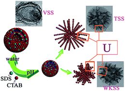
The synthesis of vesicular, walnut-kernel-, and tremella-like silica spheres (VSS, WKSS, and TSS) composed of hierarchical or U-shaped mesoporous structures by a pH-based approach was proposed. Spherical bodies with textural mesopores having sizes ranging from 30 to 40 nm were formed as a result of the diameter of the U-shaped silica skeleton.
Field emission scanning electron microscopy images of the representative samples synthesized with CTAB and SDS in different buffer solutions are shown in Fig. 1. As shown in Fig. 1a, most of the particles are intact spheres with diameters from 50 to 150 nm, and several particles are ruptured vesicular silicas, which could be attributed to the drying and calcination treatments of the sample; this figure shows these particles as being hollow spheres with relatively rough and thick shells. As seen in Fig. 1b, rather surprisingly, the buffer solution with pH of 5.0 results in two different spherical structures, and it can be seen that minor amounts of TSS, except for ruptured hollow spheres, which is occasionally observed for less stable. To further probe the effect of pH of the buffer solution on the morphology, we fabricated samples using various buffer solutions with pH range of 7.0–10.0. As expected, significant amounts of WKSS and TSS were observed in Fig. 1c and d, whereas vesicular hollow spheres disappeared completely. In particular, it was clear that all samples (Fig. 1e) exhibited better walnut-kernel-like morphology and uniformity. This was possibly an effect of the pH of the buffer solution on the morphology, i.e., on the shape of the micelles aggregation formed by a pH-based synthesis approach. Surprisingly, when pH was higher (i.e., 10.0), a small amount of irregular WKSS was formed (Fig. 1f). With pH increased to an appropriate value, the silica spheres became more uniform; however, a very high pH value led to the formation of irregular particles. The SEM (Fig. 1) images also show surprisingly high yield (≈100%) morphologies, i.e., vesicles or WKSS without any other morphology prepared in water or buffer solution (pH 9).
High-resolution transmission electron microscopy images of calcined samples are shown in Fig. 2 and Fig. S1.† Fig. 2a shows the presence of aggregated double-layer vesicles with diameters of 50 to 150 nm and a wall thickness of 5 nm. Further tuning of the pH of the buffer solution from the value of 5 causes a significant change in the surface features, in addition to the expected breaking of vesicles and aggregation of small particles to form large spheres (Fig. 2b), which are induced under acidic conditions (pH = 5);15 subsequently, walnut-kernel- and tremella-like structures appear to emerge. Increasing pH further to 7, 8, and 10 causes a significant change in the size of the nanoparticles and the pore structure (Fig. 2c, d and f). As shown in Fig. 2c, d and f, some U-shaped silica particles conglomerate to form large spherical aggregates, which result in large TSS spheres with a size of approximately 280 nm and a wall thickness ranging from 5 to 15 nm, whereas textural mesopores having sizes ranging from 30 to 40 nm are formed owing to the diameter of the U-shaped silica skeleton or voids between adjacent U-shaped silica particles. Furthermore, all particles exhibit internal mesoporosity with pore diameters ranging from 4 to 5 nm, which is attributed to the removal of the surfactant template.10 Such hierarchical porosity as an ideal host matrix may be beneficial in applications in many areas such as heterogeneous catalysis, adsorption/separation, and exhaust gas treatment. At a pH of 9.0, uniform WKSS with a size of approximately 100 nm and a wall thickness ranging from 15 to 20 nm was formed (Fig. 2f).
As shown in Fig. 3, N2 sorption analysis was further employed to observe the pore structure of the WKSS and TSS samples. All samples exhibited typical type-IIb isotherms with distinct H3-type hysteresis loops with capillary condensation at P/P0 ranging from 0.45 to 0.99.11 The pore size distribution (Fig. 3b) centered at approximately 4 nm is attributed to the removal of the surfactants (dual template), and the pore size distribution in the range of 30 to 40 nm may be associated with the diameter of the U-shaped silica skeleton or voids between adjacent U-shaped silica skeletons; these results are in accordance with the TEM results. Additionally, SS-8 exhibits a much larger SBET (252.04 m2 g−1) than SS-5 (130.85 m2 g−1), SS-7 (78.90 m2 g−1), SS-9 (94.78 m2 g−1), and SS-10 (90.65 m2 g−1), as well as a much larger total adsorption pore volume of 0.78 cm3 g−1 than those of SS-5 (0.60 cm3 g−1), SS-7 (0.43 cm3 g−1), SS-9 (0.65 cm3 g−1), and SS-10 (0.51 cm3 g−1). The ravine structure effectively increased the specific surface area of the walnut-kernel- and tremella-like silica, while the easily accessible high surface areas and active sites inside the pores promote their applications for particular significant mass transport.18
Fig. 3 (a) N2 adsorption–desorption isotherms and (b) corresponding Barrett–Joyner–Halenda (BJH) pore size distribution curves of VSS, SS5, SS7, SS8, SS9, and SS10. |
To investigate the sample structure further, small-angle X-ray diffraction experiments were conducted on calcined samples. The results are shown in Fig. 4. All samples have one broad peak at approximately 2θ = 1.7°,12 indicative of a relatively ordered pore structure and relatively stable framework under the reaction conditions.13
The proposed structures and the mechanisms for the formation of VSS, WKSS, and TSS in water solutions and buffer solutions with different pH values are illustrated in Scheme 1. In the water solution system (Scheme 1a), both hydrophobic and electrostatic interactions between CTAB and SDS surfactants drove the formation of the stable bilayer vesicle.14 Careful adjustment of the pH reaction conditions (Scheme 1b and c) resulted in the formation of spherical micelles by the CTAB/SDS dual surfactants. Simultaneously, the strong ionic effect from the buffer solution promoted the agglomeration between the spherical micelles, which caused the formation of U-shaped novel micelle aggregates.17 The U-shaped micelle aggregates further self-assembled into spherical structures with ravined or wrinkled surface through head–head or tail–tail interaction. The diameter of the U-shaped micelle aggregates can vary with a change in the pH value. The U-shaped micelle aggregates slowly interacted because of their similar hydrophilic head groups. The aggregates finally agglomerated into spherical structures with walnut-kernel- and tremella-like arrangements through self-assembly, in which TEOS can hydrolyze in the hydrophilic units of the aggregates. Then, U-shaped silica particles were formed via the hydrolysis and polycondensation of TEOS. Finally, silica spheres composed of U-shaped mesoporous structures in the U-shaped walls were obtained via calcination to remove the organic template (CTAB/SDS micelle). These particles look like collapsed hollow particles with wrinkled surface.
Scheme 1 Schematic representation of proposed formation of (a) VSS, (b) TSS, and (c) WKSS using CTAB and SDS as complex templates. |
Footnote |
† Electronic supplementary information (ESI) available: Characterization of samples. See DOI: 10.1039/c4ra04294h |
This journal is © The Royal Society of Chemistry 2014 |