High photocatalytic activity of ‘clicked’ iron phthalocyanine conjugated with carbon nanofibers†
Zhenjun Chang* and
Jing Zeng
College of Materials Science and Engineering, Jiangsu University of Science and Technology, Zhenjiang, Jiangsu 210001, People's Republic of China. E-mail: zjchang@just.edu.cn
First published on 13th August 2014
Abstract
Carbon nanofibers were used for the first time as substrates for the immobilization of photocatalytically active iron phthalocyanines by combining electrospinning and ‘click’ chemistry. The hybrid nanofibers exhibited high photocatalytic activity.
Carbon nanofibers (CNFs) possess high mechanical strength and moduli, and excellent electrical and thermal conductivities, as well as chemical resistance. They have been widely used as an ideal substrate for electron pathways for the efficient capture and transport of photogenerated electrons. The surface grafting of functional molecules onto CNFs can widen its range of applications. But, it is difficult to covalent modification with various functional molecules. Previous studies have reported on the grafting of functional groups to CNFs in harsh reaction conditions.1–3
As functional molecules, phthalocyanines (Pc), especially metal phthalocyanines, are two-dimensional aromatic molecules, able to self-assemble into stacks through p–p supramolecular interactions.4 These macrocycles possess outstanding electrical and optical properties that make them attractive for a variety of uses, such as gas sensors, catalysts, photosensitizers, and dye sensitized solar cells. Among these different applications, the use of Pc as photocatalysts for visible-light induced photocatalytic degradation of organic pollutants has excited much interest.5–7 However, the disaggregation behaviour of Pc is crucially important to the performance of the photocatalyst as this application is restricted by the tendency for aggregation observed in Pc which contributes to an impairment of the photocatalytic activity. Immobilization of Pc by the formation of micro/nano nanoparticle or nanorod substrates provides a promising approach to overcoming the drawbacks.6,7 However, the photocatalytic materials produced this way cannot be recycled after the photocatalytic process and thus contributes to secondary pollution.
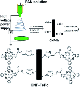
Electrospinning is a highly versatile method for processing solutions or melts, mainly of polymers, into continuous fibers with diameters in the nano- to microscale range.8–10 CNFs can been easily prepared by this technology. Similar to the substrates mentioned above, electrospun CNFs also show several remarkable characteristics such as porosity and high surface area to volume ratio.11 Furthermore, the macroscopic-scale alignment in the axial direction of the electrospun nanofibers makes its recycling much easier. Recently, other groups as well as ours employed electrospun polymer nanofibers as substrates for various functional molecules,12–15 also Pc immobilization.16,17 However, judging from the excellent photocatalytic property of Pc and the efficient electron transfer property of CNFs, combination of Pc and CNFs by covalent bond seems to be ideal for hindering the recombination of electrons and holes and improving the photocatalytic efficiency. Recently, click chemistry has attracted significant attention in polymer and materials science. In particular, the Cu1-catalyzed click reaction results in 1,3-dipolar cycloaddition between azides and alkynes. The mechanism of the reaction involved the formation of CuI acetylide, then of a metallaheterocycle that is further protonated yielding the 1,2,3-triazoles.18 The reaction provides products stereoselectively with high yields, produces inoffensive byproduct, and is insensitive to oxygen and water. To our knowledge, there has been no report on the fabrication of azide functionalized electrospun CNFs using iodine azide (IN3) solutions with a gentle method, and Pc immobilized onto CNFs via the click reaction. In this study, we employed click coupling to use carbon nanofibers as a backbone to support Pc. The experimental procedure is shown in Fig. 1. The photocatalytic properties of the hybrid nanomaterials are discussed. The recycling performance is also analyzed.
In general, three processes are needed in sequence for the preparation of propargyl phthalocyanine iron (alkyne–FePc) grafted CNFs (CNF–FePc) (see ESI†): CNF preparation, azide-decorated CNF (CNF–N3) preparation and click coupling of CNF–N3 and alkyne–FePc. In the study, CNFs were prepared by combining the electrospinning and carbonization processes. In this method, polyacrylonitrile (PAN) was used as the precursor for the carbon nanofibers. PAN (Mw = 70![[thin space (1/6-em)]](https://www.rsc.org/images/entities/char_2009.gif) 000) powders were first dissolved in N,N-dimethylformamide (DMF) to prepare a 7 wt% solution. Carbon nanofibers were prepared via electrospinning from the PAN/DMF solution, followed by carbonization.19 The CNF–N3 were prepared according to the procedure of Landis and McCrory et al.20,21 0.06 g of sodium azide was added to 30 mL of acetonitrile at 0 °C, and afterwards 0.039 g of iodine monochloride (ICl) was added. The CNFs were immersed in the IN3 reaction solution for 1, 2, 4 h to obtain CNF–N3. The alkyne–FePc was prepared via cyclotetramerisation, followed by esterification, according to our previous report.16 CNF–Pc was obtained via click coupling of the CNF–N3 and alkyne–FePc. Grafting yield was defined as Wa − Wb/Wb, where Wa and Wb are the weights of the CNF–N3 after and before click coupling. This values for CNF–FePc were about 5%, 11% and 21%.
000) powders were first dissolved in N,N-dimethylformamide (DMF) to prepare a 7 wt% solution. Carbon nanofibers were prepared via electrospinning from the PAN/DMF solution, followed by carbonization.19 The CNF–N3 were prepared according to the procedure of Landis and McCrory et al.20,21 0.06 g of sodium azide was added to 30 mL of acetonitrile at 0 °C, and afterwards 0.039 g of iodine monochloride (ICl) was added. The CNFs were immersed in the IN3 reaction solution for 1, 2, 4 h to obtain CNF–N3. The alkyne–FePc was prepared via cyclotetramerisation, followed by esterification, according to our previous report.16 CNF–Pc was obtained via click coupling of the CNF–N3 and alkyne–FePc. Grafting yield was defined as Wa − Wb/Wb, where Wa and Wb are the weights of the CNF–N3 after and before click coupling. This values for CNF–FePc were about 5%, 11% and 21%.
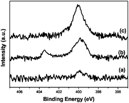
X-ray photoelectron spectroscopy (XPS) was used for distinguishing the surface of the azide from the CNFs and understanding the click reaction linking FePc to the CNFs. The change of the N 1s peak is usually characteristic of the click reaction process. The N 1s spectra of CNF–N3 shows two peaks at 403.5 and 400.0 eV (Fig. 2b). The peak at 403.5 eV was assigned to the central, electron-deficient nitrogen of the azide group. After the click reaction, the peak at 403.5 eV disappeared, which indicates the conversion of the azide groups to the 1,2,3-triazole ring during the cycloaddition reaction.20 Moreover, only one N 1s signal can be observed at 400.0 eV, and the peak attributed to nitrogen from 1,2,3-triazole and Pc is quite broad. In addition, the FT-IR spectrum of CNF–N3 clearly revealed the appearance of an absorbance peak at 2105 cm−1, which is characteristic of the azide groups (Fig. S1†).13 After click reaction, the azide stretching band at 2105 cm−1 completely disappeared, confirming that the azide groups were all consumed in the reaction.
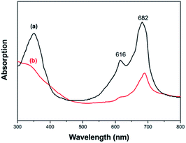
The optical absorption spectra of FePc in DMF solution and CNF–FePc films was obtained with a UV-vis absorption spectrometer. As shown in Fig. 3a and b, the large peak in the region of 550–750 nm corresponds to HOMO (highest occupied molecular orbital) and LUMO (lowest unoccupied molecular orbital) transition (Q-band), which can be assigned to the π–π* transition of monomers from the HOMO to the LUMO.22 Two split absorption bands are observed in Fig. 3a, which are because of monomer absorption (682 nm) and aggregate absorption (616 nm). The aggregate absorption is present because the layer macrocycles tend to aggregate in the solvent.23 After FePc was grafted onto the nanofiber surface, it exists only in the form of absorbed monomer, suggesting a significant enhancement in the Pc disassociation (Fig. 3b).
A scanning electron microscope (SEM) was used for microstructural examination by evaluating the effect of the surface functionalization of CNFs with FePc (grafting yield, 21%) as a result of the click reaction. The SEM image of the CNFs (Fig. 4a) showed that the sample was much smoother than that of CNF–FePc (Fig. 4b). After coupling of the FePc with the CNFs, the morphology of the fibers was retained as shown in Fig. 4b for the CNF–FePc sample. Further structural characterization showed many scalelike structures deposited on the surface of the CNFs, indicating that a dense FePc was grafted onto the CNFs. Fig. 4c and d shown TEM images of pristine CNFs (c) and CNF–FePc (d), some scalelike structures were also found on the surface of CNFs. Even after washing with excess DMF and water, the FePc could not be detached from the CNFs because of the strong covalent bond.
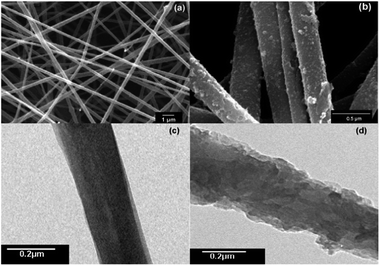 | ||
| Fig. 4 SEM and TEM images of pristine CNFs (a and c) and CNF–FePc with 21% grafting yield (b and d), respectively. | ||
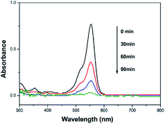
In order to investigate the photocatalytic activity of CNF–FePc, rhodamine B (RhB, a kind of commercial non-biodegradable toxic dye), was selected as the model for a photocatalytic material. The photocatalytic properties of the prepared CNF–FePc (grafting yield, 21%) were evaluated by measuring the absorption intensity of RhB at 550 nm. A 100 mL RhB solution was used for photocatalytic test. The initial concentration of RhB in the aqueous solution was 5 mg L−1. The temporal evolution of the UV-vis spectra recorded during the photocatalytic degradation of RhB by CNF–FePc (0.6 g L−1) using hydrogen peroxide (H2O2, 0.1 mol L−1) is shown in Fig. 5. The change in absorption spectra of the RhB aqueous solution demonstrated the change in its concentration. The difference in concentration as a result of the degradation of RhB is expressed as a change in the C/C0 value, where C0 and C are the initial concentration and residual concentration of RhB respectively. Solutions were collected every 30 min to measure the RhB degradation. After photocatalytic reaction of 90 min, the concentration of the RhB solution was found to have reduced to about 4%, indicating that the hybrid nanofibers exhibit high photocatalytic activity. Moreover, we found that the amount of grafting of alkyne–FePc was affected by the amount of azide groups of CNFs. The different grafting amount (5%, 11% and 21%) of alkyne–FePc anchored on the CNFs were given by different reaction time in azide process, followed same reaction conditions in click reaction. TEM images (Fig S2† and 4d) showed the increase of FePc with increasing grafting yields, indicating more azide groups for the click coupling on the surface of CNFs can been obtained with increasing reaction time. The effects of the grafting yields on photocatalytic degradation of RhB were shown in Fig. S3.† We found that the photocatalytic efficiency was improved with increasing grafting yields.
In the comparative experiments, the CNFs, CNFs–H2O2 and alkyne–FePc–H2O2 were used as references to understand the photocatalytic activity of the CNF–FePc. The RhB concentration in CNFs was slightly decreased because of physical adsorption (Fig. 6a). Similarly, the RhB concentration in the CNFs–H2O2 did not markedly reduce (Fig. 6b). The degradation effectiveness of alkyne–FePc–H2O2 (Fig. 6c) with the same weight as the grafted alkyne–FePc in CNF–FePc was about 47% after 90 min. Obviously, the photocatalytic efficiency of alkyne–FePc–H2O2 is significantly lower than for CNF–FePc–H2O2 (see Fig. 6d, colour almost vanished after 90 min). The observed enhancement of photocatalytic activity is most likely due to a relative increase in the active site concentration resulting from the ultra-high surface area in the hybrid nanofibers, the disaggregation of the FePc from CNF–FePc, as well as the possible electron pathways which efficiently capture and transport photogenerated electrons from the CNFs.19 A possible mechanism was being discussed to explain the enhancement of the photocatalytic properties of the CNF–FePc (Fig. 7). In the present system H2O2 is added to the iron center of FePc to give HOOFePc.24 Upon visible light irradiation, HOOFePc can be excited to form a transition state HOOFePc*. The O–O band cleavage of HO–OFePc* can be rapidly cleaved to generate the hydroxyl radicals (HO˙), which was a powerful oxidizing agent to degrade RhB.24,25 The photogenerated electrons from this reaction may move freely toward the surface of the highly conductive CNFs. These HO˙ radicals will react immediately with RhB+ and degrade them effectively. Furthermore, dissolved oxygen molecules reacted with transferred electrons on the surface of CNFs from conduction band (CB) of Pc to yield superoxide radical anions (O2˙−), which on protonation generated the hydroperoxy radicals (HO2˙), producing hydroxyl radicals HO˙, which can still degrade RhB+.19,26,27
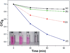 | ||
| Fig. 6 Photodegradation of RhB in the presence of (a) CNFs, (b) CNFs–H2O2, (c) alkyne–FePc–H2O2 and (d) CNF–FePc–H2O2. | ||
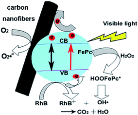 | ||
| Fig. 7 The proposed mechanism for the H2O2 assistant photocatalysis of the CNF–FePc nanofibers under visible light irradiation. | ||
The performance of a photocatalyst in the recycling experiments is significant for its practical application in solutions to environmental problems. After the first photocatalytic reaction process, the CNF–FePc were collected. The hybrid nanofibers were soaked in deionized water for 10 min, then washed with deionized water. This procedure was repeated three times. Finally, the CNF–FePc was dried in a vacuum oven at 60 °C. The other cycles were carried out in a similar way. As shown in Fig. S4,† after the four-cycle experiments, the photocatalytic activity of the CNF–FePc nanofibers decreased slightly. This indicated that the CNF–FePc still displayed enough efficient photocatalytic activity for the degradation of RhB, and could thus easily be separated for reuse. After four-cycle experiments, no significant changes were shown in SEM (Fig. S5†), indicating the FePc could not be detached from the CNFs. The explanation of this cycle experiment is, without organic pollutants in system, the HO˙ radicals could rapidly recombine with the intermediates for producing new HOOFePc, which can recycle use.25
In summary, for the first time, CNFs, were used as the substrate of grafting FePc by a gentle and efficient method. CNF–FePc was prepared by a gentle azide process and click reaction. Its potential application in the degradation of organic pollutants such as RhB solution was evaluated. The CNF–FePc displayed excellent photocatalytic performance and could be easily separated and reused. The structure can thus avoid the aggregation behavior of Pc in solutions and facilitates the recycling of the photocatalyst. CNFs can increase capture and transport of photogenerated electrons. The development of phthalocyanine functionalized nanofibers are thus good candidates for waste treatment. More importantly, the CNF–N3 is a promising candidate for a functional substrate to be used in immobilization of various functional molecules required in multiple applications.
Acknowledgements
This work was supported by the National Natural Science Foundation of China (no. 51203068), and the start-up fund of Jiangsu University of Science and Technology (no. 35061103).Notes and references
- K. L. Klein, A. V. Melechko, T. E. McKnight, S. T. Retterer, P. D. Rack, J. D. Fowlkes, D. C. Joy and M. L. Simpson, J. Appl. Phys., 2008, 103, 061301–061326 CrossRef PubMed.
- B. L. Fletcher, T. E. McKnight, A. V. Melechko, M. L. Simpson and M. J. Doktycz, Nanotechnology, 2006, 17, 2032–2039 CrossRef CAS.
- L. Li and C. M. Lukehart, Chem. Mater., 2006, 18, 94–99 CrossRef CAS.
- H. Yaku, T. Fujimoto, T. Murashima, D. Miyoshi and N. Sugimoto, Chem. Commun., 2012, 48, 6203–6216 RSC.
- P. Kumar, A. Kumar, B. Sreedhar, B. Sain, S. S. Ray and S. L. Jain, Chem.–Eur. J., 2014, 20, 1–9 CrossRef PubMed.
- M. Silva, M. J. Calvete, N. P. Gonçalves, H. D. Burrows, M. Sarakha, A. Fernandes, M. F. Ribeiro, M. E. Azenha and M. M. Pereira, J. Hazard. Mater., 2012, 233–234, 79–88 CrossRef CAS PubMed.
- Y. Fang and D. J. Chen, Mater. Res. Bull., 2010, 45, 1728–1731 CrossRef CAS PubMed.
- A. Greiner and J. H. Wendorff, Angew. Chem., Int. Ed., 2007, 46, 5670–5703 CrossRef CAS PubMed.
- W. E. Teo and S. Ramakrishna, Nanotechnology, 2006, 17, R89–R106 CrossRef CAS PubMed.
- D. Li and Y. Xia, Adv. Mater., 2004, 16, 1151–1170 CrossRef CAS PubMed.
- J. S. Lee, O. S. Kwon, D. H. Shina and J. Jang, J. Mater. Chem. A, 2013, 1, 9099–9106 CAS.
- Z. J. Chang, Chem. Commun., 2011, 47, 4427–4429 RSC.
- Z. J. Chang, Y. Xu, X. Zhao, Q. H. Zhang and D. J. Chen, ACS Appl. Mater. Interfaces, 2009, 1, 2804–2811 CAS.
- Y. L. Li, D. K. Lee, J. Y. Kim, B. S. Kim, N. G. Park, K. Kim, J. H. Shin, I. S. Choi and M. J. Ko, Energy Environ. Sci., 2012, 5, 8950–8957 CAS.
- F. Kayaci, C. Ozgit-Akgun, N. Biyikli and T. Uyar, RSC Adv., 2013, 3, 6817–6820 RSC.
- Z. J. Chang, Y. Fang, Q. H. Zhang and D. J. Chen, Chem. Lett., 2009, 38, 1144–1145 CrossRef CAS.
- S. L. Chen, X. J. Huang and Z. K. Xu, Cellulose, 2012, 19, 1351–1359 CrossRef CAS.
- L. Y. Liang and D. Astruc, Coord. Chem. Rev., 2011, 255, 2933–2945 CrossRef CAS PubMed.
- J. B. Mu, C. L. Shao, Z. C. Guo, Z. Y. Zhang, M. Y. Zhang, P. Zhang, B. Chen and Y. C. Liu, ACS Appl. Mater. Interfaces, 2011, 3, 590–596 CAS.
- E. C. Landis and R. J. Hamers, Chem. Mater., 2009, 21, 724–730 CrossRef CAS.
- C. C. L. McCrory, A. Devadoss, X. Ottenwaelder, R. D. Lowe, T. D. P. Stack and C. E. D. Chidsey, J. Am. Chem. Soc., 2011, 133, 3696–3699 CrossRef CAS PubMed.
- Z. C. Guo, C. L. Shao, J. B. Mu, M. Y. Zhang, Z. Y. Zhang, P. Zhang, B. Chen and Y. C. Liu, Catal. Commun., 2011, 12, 880–885 CrossRef CAS PubMed.
- P. J. Camp, A. C. Jones, R. K. Neely and N. M. Speirs, J. Phys. Chem. A, 2002, 106, 10725–10732 CrossRef CAS.
- Y. P. Huang, J. Li, W. H. Ma, M. M. Cheng, J. C. Zhao and J. C. Yu, J. Phys. Chem. B, 2004, 108, 7263–7270 CrossRef CAS.
- X. Tao, W. H. Ma, T. Y. Zhang and J. C. Zhao, Chem.–Eur. J., 2002, 8, 1321–1326 CrossRef CAS.
- M. Y. Zhang, C. L. Shao, Z. C. Guo, Z. Y. Zhang, J. B. Mu, T. P. Cao and Y. C. Liu, ACS Appl. Mater. Interfaces, 2011, 3, 369–377 CAS.
- M. Samadi, H. A. Shivaee, A. Pourjavadi and A. Z. Moshfegh, Appl. Catal., A, 2013, 466, 153–160 CrossRef CAS PubMed.
Footnote |
| † Electronic supplementary information (ESI) available: Experimental details, Fig. S1–S5. See DOI: 10.1039/c4ra04823g |
| This journal is © The Royal Society of Chemistry 2014 |

