 Open Access Article
Creative Commons Attribution 3.0 Unported Licence
Mesoporous graphite nanoflakes via ionothermal carbonization of fructose and their use in dye removal†
Zai-Lai
Xie
*a,
Xing
Huang
b,
Maria-Magdalena
Titirici
c and
Andreas
Taubert
*a
aInstitute of Chemistry, University of Potsdam, D-14476 Potsdam, Germany. E-mail: zailai.xie@gmail.com; ataubert@uni-potsdam.de
bFritz Haber Institute of the Max Planck Society, D-14195 Berlin, Germany
cQueen Mary University of London, School of Engineering and Materials Science, London, E1 4NS, UK
First published on 13th August 2014
Abstract
The large-scale green synthesis of graphene-type two-dimensional materials is still challenging. Herein, we describe the ionothermal synthesis of carbon-based composites from fructose in the iron-containing ionic liquid 1-butyl-3-methylimidazolium tetrachloridoferrate(III), [Bmim][FeCl4] serving as solvent, catalyst, and template for product formation. The resulting composites consist of oligo-layer graphite nanoflakes and iron carbide particles. The mesoporosity, strong magnetic moment, and high specific surface area of the composites make them attractive for water purification with facile magnetic separation. Moreover, Fe3C-free graphite can be obtained via acid etching, providing access to fairly large amounts of graphite material. The current approach is versatile and scalable, and thus opens the door to ionothermal synthesis towards the larger-scale synthesis of materials that are, although not made via a sustainable process, useful for water treatment such as the removal of organic molecules.
Introduction
Graphene, currently one of the most popular two-dimensional materials, is a well-known carbon aIlotrope consisting of a single layer of sp2 carbon atoms.1,2 The exceptional electronic and mechanical properties of graphene lend themselves to applications in electronics,3,4 chemical sensing,5 and catalysis.6 For graphene to be technologically successful, viable synthesis and purification processes for much larger amounts of material than are currently available are highly sought after.1,3,4,7–10 Indeed high-quality graphene films have been prepared by chemical vapor deposition of hydrocarbons on metal substrates,11–16 but the accessible amounts are far from what is needed for large-scale applications.One viable synthesis is chemical oxidation and exfoliation of graphite. It is amenable to large-scale production and therefore remains the most important pathway for bulk graphene synthesis.9,17,18 However, graphite exfoliation is a multistep and rather energy-intensive process. In view of the growing demand for facile chemical processes, new and efficient approaches towards larger amounts of graphene-type materials are clearly required. A sustainable process towards graphene-like materials from simple organic molecules such as glucose has recently been put forward; the reaction either proceeds through an intermediate carbon nitride (C3N4) or uses molten metal chloride salts as the solvent and template.7,19
Other molten salts, ionic liquids (ILs), are now established solvents,20,21 templates,22 and precursors for inorganic materials,8,23–27 and as stabilizers for exfoliated graphite.9,28 Moreover, the preparation of advanced carbons in ILs, in particular via ionothermal synthesis, is a promising approach towards functional carbon-based materials.8,22–24,29 As of now, iron-containing ILs have been among the most actively studied ILs for the carbonization of biomass and other carbon precursors.8,29 For instance, hierarchical porous carbon nanoparticles can be obtained by simply heating biomass in iron-containing ILs. The process takes advantage of the multiple roles ILs can play as catalysts, templates and structure directing agents for carbon formation. Especially iron is an efficient promoter of the polymerization and dehydration of carbohydrates and the subsequent formation of graphitic structures.25 Iron-containing ILs possess unique properties: i.e. the cation can serve as a template,29 whereas its anion is catalytically active26,30 and enables the synthesis of graphene-type materials.25 Indeed, Dai et al. reported that graphene-type powders can be prepared with metal halide-ionic liquids as the carbon source and magadiite (a layered sodium silicate) as the template.8 Layered templates like magadiite play a crucial role that enable intercalation of metal-halide ionic liquids between layers prior to carbonization and thus promote the formation of 2D instead of 3D materials. This approach, however, requires the removal of the silicate template with toxic fluorine-containing reagents such as HF or ammonium fluorides.8 Therefore, a facile, large scale, and non-hazardous towards graphene-type materials is highly desirable.
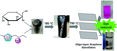
Herein, fructose and 1-butyl-3-methylimidazolium tetrachloridoferrate(III), [Bmim][FeCl4] are selected as an example to study the carbonization of biomass in the presence of an iron-containing IL, Scheme 1. The resulting composite is mesoporous, magnetic, and rich in sp2 carbons. These properties enable the removal of organic dyes such as rhodamine B from contaminated water using adsorption and magnetic separation.
Results
As depicted in Scheme 1, low temperature (LT, 180 °C) ionothermal carbonization of fructose results in monolithic carbon ionogels. Carbon ionogels are versatile and fascinating hybrid materials comprised of a carbon framework and ILs incorporated within the carbon network.31 The high homogeneity of all monoliths suggests that they are stabilized by strong interactions between the carbon network and the IL constituents such as Coulombic interactions and physical adsorption.31Direct carbonization of carbon ionogels at 750 °C under nitrogen results in high temperature (HT, 750 °C) ionothermal carbons. X-ray diffraction (XRD) patterns of HT ionothermal carbons clearly show the presence of graphitic carbon and iron carbide (Fig. 1A). The reflection at 26° could be related to a reasonably ordered (002) interlayer carbon packing.32 The reflection is well resolved and sharp, suggesting that the materials are highly oriented graphitic structures.33 Additionally, there are a number of diffraction peaks centered at ∼45° (2θ) which can be assigned to Fe3C (JCPDS 65-0393) within the graphitic matrix.25 The strong and sharp diffraction peaks corresponding to Fe3C suggest the formation of fairly large and well crystallized particles.
Raman spectroscopy, Fig. 1B, supports the assignment of turbostratic graphitic carbon. Spectra obtained from the ionothermal carbons show three characteristic peaks at 1340, 1574, and 2672 cm−1, respectively. Narrow D and G bands along with a strong 2D band indicate partial ordering of the graphite sheets. Moreover, the intensity ratio of ID/IG (1.04) indicates that numerous sp3 defect sites are also present.8,16,34,35
The N2 sorption isotherm and pore size distribution of the final materials are shown in Fig. 1C. Barret–Joyner–Halenda (BJH) analysis yields a surface area of 122 m2 g−1. The characteristic type IV isotherm indicates the presence of mesopores without a significant fraction of micropores.29,36,37 The latter is confirmed by the fairly broad hysteresis loop, which closes upon desorption. This indicates capillary condensation and swelling effects.29 The hysteresis loop indicates unrestricted adsorption in the high pressure regime and the increased gas uptake at p/p0 > 0.9 indicates the presence of slit-like pores.38 The mesopores are emptied by a cavitation mechanism, as indicated by the spontaneous desorption at p/p0 ∼ 0.45.38 Non-linear density functional theory (NLDFT) analysis yields a pore distribution with relatively monodisperse pore diameters around 5 nm.
Consistent with XRD and Raman data, TEM and high angle annular dark field scanning TEM (HAADF-STEM) images reveal the presence of a graphite matrix and agglomerated iron carbide particles (Fig. 2). The presence of Fe3C is confirmed by energy dispersive X-ray spectroscopy (EDXS) on individual nanoparticles, which clearly shows the presence of iron and carbon. The large particles observed in (S)TEM are also consistent with the fairly intense and narrow reflection in XRD.
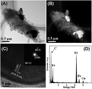 | ||
| Fig. 2 TEM and HAADF-STEM images (A and B) and HRTEM and corresponding EDXS analysis (C and D). Inset is a selected area FFT pattern of the sample shown in (C). | ||
High resolution TEM (HRTEM) and TEM-selected area fast Fourier transform (FFT) again support the formation of Fe3C and suggest that the Fe3C particles in fact are mesocrystals39 or particles formed by oriented attachment.40,41 The lattice fringes of the Fe3C (1 0 0) crystalline plane, with d-spacing of 0.5 nm, can clearly be seen from the HRTEM image. Moreover, all TEM data show that, besides the large Fe3C particles within the samples, other domains mainly consist of carbon nanoflakes, indicating a relatively heterogeneous distribution of the Fe3C nanoparticles in a homogeneous carbon matrix.
The surface morphology of an as-synthesized HT ionothermal carbon is shown in Fig. 3A. The carbon surfaces exhibit unique petal-like and interconnected nanoflakes with a mean size in the micrometer range. Complementary transmission electron microscopy (TEM) finds a flake-like nanomorphology composed of stacked graphene-type sheets. The interconnected nature of the nanoflakes likely generates the mesopores within the carbon frameworks. The nanoflakes have highly homogenous morphologies, but vary in their thickness.
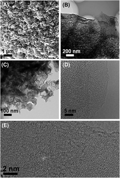 | ||
| Fig. 3 SEM (A) and TEM images at increasing magnifications (B–E) of a graphite composite (D and E are HRTEM images). | ||
High resolution TEM (HRTEM) clearly shows lattice fringes in the carbon, confirming the carbon's graphitic nature. The interplane spacing measured from different nanoflakes is in the range between 0.33–0.38 nm, similar to that of carbon nanosheets (0.34 nm) reported previously.42 The typical honeycomb-like molecular structure of hexagonally connected carbon atoms is observed in many unfolded carbon sheets. These domains are fairly small on the order of a few nm. Besides the single carbon nanosheets mostly discussed so far, all samples also contain multilayer domains; we hence call the materials obtained via our approach “oligo-layer graphite” (OLG) nanoflakes.
The iron carbide particles within the mesoporous graphite nanoflakes are accessible through the pores. Treatment of the materials with dilute hydrochloric acid results in the dissolution of the iron carbide nanoparticles. XRD patterns of the acid-treated materials exclusively show reflections from carbon and all reflections corresponding to iron carbide are gone after 48 hours of acid etching (Fig. S1†). This is also confirmed by TEM, which shows no significant changes in the graphite nanoflake morphologies, but no more dark speckles indicative of the Fe3C nanoparticles. This indicates that the acid etching does not affect the carbon sheets, but selectively removes the iron carbide from the samples.
Additional X-ray elemental mapping experiments were performed for further chemical analysis of the acid-etched samples (Fig. 4). X-ray maps show that the carbon is homogeneously distributed, and oxygen is also present in the sample. In spite of the fact that XRD (Fig. S1†) does not show any indication of iron carbide or iron chloride, X-ray analysis still finds iron and chlorine signals homogeneously distributed throughout all samples. The apparent contradiction between the fact that XRD does not detect any iron-based mineral phases anymore (Fig. S1†) while EDXS (Fig. 4D) still detects Fe can be assigned to (i) rather low concentrations of Fe after the etching process (which can still be detected by X-ray mapping, which is a local method, but not by XRD, which is a global method) or (ii) small fractions of residual anhydrous iron chloride, which has a poor solubility in dilute aqueous hydrochloric acid and does not generate an XRD signal if poorly ordered. EDX spectrum after etching again support that Fe signal is much lower than that of as-prepared Fe3C@OLG materials shown in Fig. 2D (Fig. S2†). With the stripping of iron carbide by HCl treatment, the surface areas of ionothermal carbon increase from 122 to 180 m2 g−1, probably due to the change of materials density after removing of large Fe3C particles (Fig. S3†).
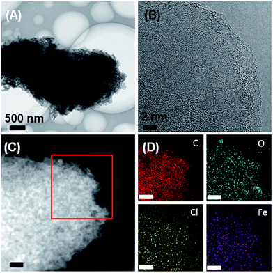 | ||
| Fig. 4 (A, B) TEM images, (C) HAADF-STEM image and (D) X-ray maps of the OLG after acid etching. Scale bars in panels (C) and (D) are 200 nm. | ||
As stated in the introduction, magnetic carbon materials are candidates for water purification.43,44 In addition, graphite materials with high specific surface areas are useful for adsorption of (mostly unpolar) organic molecules.45 The OLGs prepared here are clearly attractive for water treatment because they are relatively hydrophobic and, as demonstrated by XRD and Raman spectroscopy (Fig. 1), contain a high fraction of aromatic sp2 carbon atoms. Indeed, the OLG can be dispersed in toluene but precipitate in water (Fig. S4†).
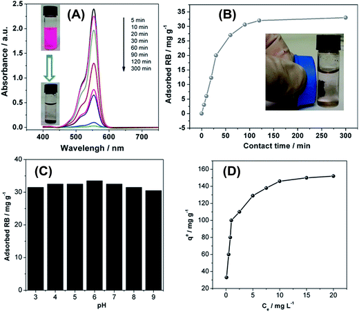
This implies a high affinity for organic molecules, such as dyes or aromatics which often are hydrophobic, but still present in aqueous media in concentrations posing a risk to the environment.46 To evaluate the OLG materials for the removal of organic molecules from water, we have studied the adsorption of rhodamine B (RB) from aqueous solution (Fig. 5) as a model reaction. Adsorption kinetics was studied at an initial RB concentration of 25 mg L−1 in water. Adsorption was monitored by UV-vis spectroscopy vs. adsorption time. Fig. 5A shows that the RB absorbance gradually decreases with increasing contact time. Visual inspection of the respective solutions confirms that a large fraction of RB is removed from the aqueous phase leaving behind a clear solution after 5 hours. The adsorbent can be easily extracted for reuse by magnetic filtration. As shown in Fig. 5B, equilibrium is reached after 120 min of contact time.
Fig. 5C shows that the solution pH only has a weak influence on the adsorption performance between pH 3 and 9. These results suggest that the OLGs could effectively adsorb RB over a wide pH range without significantly altering the adsorption characteristics. The key advantage of the OLG material over other materials used for dye removal is that the adsorption capacity of the current OLGs reaches up to 150 mg g−1, as illustrated in Fig. 5D and Table 1. This is significantly better both in terms of equilibrium adsorption time (which translates into speed or rate of a technical process) and capacity (which translates into amount of RB removed by the material per adsorbent weight unit). We currently surmise that the RB adsorption onto the OLG material is due to strong van der Waals, hydrophobic, and π–π interactions between OLG nanoflakes and the dye molecules. Also, the mesoporosity and high surface areas of the current material lend it to having the satisfactory RB adsorption performance.
| Sorbents | Capacity (mg g−1) | Contact time (min) | Reference |
|---|---|---|---|
| OLG nanoflake | 150 | 120 | This work |
| Graphite oxide (GO) | 29 | 180 | Ramesha et al.47 |
| Reduced GO | 13.15 | 250 | Ramesha et al.47 |
| Hybrid of reduced graphene oxide–Fe3O4 | 50 | 720 | Geng et al.45 |
| Multiwalled CNTs | 36 | 180 | Yan et al.48 |
| Activated carbon | 307 | 720 | Li et al.49 |
| Activated carbon | 212 | Not mentioned | Anandkumar et al.50 |
| Activated carbon | 16 | 150 | Kadirvelu et al.51 |
Discussion
Ionic liquids are promising active components for the creation of (multi)functional materials.23,52 Among others, there is an increasing research and technology effort in making use of ILs for the preparation of carbon-based materials.8,26,29 One major advantage for using of ILs as precursors for carbons is that heteroatom doping (such as N, B, S) and metal doping can be accomplished fairly easily.53 Moreover, the almost unlimited flexibility of IL structure and chemical composition makes them highly suitable for tuning carbon structure with desirable electronic properties or specific surface area.54 As stated in the introduction, however, there is a lack of protocols for the large-scale synthesis of graphene-like materials. The current article provides a viable approach towards nano- and mesotructured graphitic carbon using a sustainable raw material (although the OLG synthesis as such is clearly not sustainable at the moment), fructose, and an IL that is easily accessible on a large scale.Iron-based ionic liquids are interesting components not only because they are magnetic55 or catalytically active.30,56,57 They can also serve as powerful solvents for biomass conversion.29 [Bmim][FeCl4] has been used as precursor for iron/iron carbide and graphene-type materials synthesis in the presence of an inorganic template. For instance, Göbel et al. synthesized Fe/Fe3C/C hybrid materials with rather high surface areas using functionalized SiO2 as template and [Bmim][FeCl4] as precursor.25 Dai et al. synthesized graphene-type carbon powders by pyrolysis of iron-based ILs and magadiite, a layered sodium silicate.8 Moreover, we have previously shown that the IL [Bmim][FeCl4] is an effective medium for conversion of biomass to porous carbons at relatively low temperature.29 This process results in a monolithic carbon ionogel. In spite of focusing on different final materials, all studies used the same IL, showing its potential for a wide variety of chemical transformations. Especially given the fact that both biomass and iron chloride are relative low-cost, the large-scale synthesis of such carbon ionogels can be economically achieved, possibly by adapting the chemistry of the IL from imidazolium-based (which still constitute more expensive ILs) to ILs based on other cations such as ammonium, which may be cheaper.
Carbonizing of as-synthesized carbon ionogels leads to graphite nanoflakes. For structure assignments, we have used various techniques. SEM and TEM (Fig. 2 and 3) indicate an “oligo-layer-graphite” (OLG) morphology with characteristic thin graphite nanoflakes, thus justifying the term “oligo-layer-graphite”. Remarkably, the honeycomblike molecular structure corresponding to single-layer graphene is clearly seen in HRTEM (Fig. 3E), confirming the formation of graphene-like materials at low carbonization temperature of only 750 °C. Our approach thus introduces a new strategy towards graphite composites containing highly ordered graphitic structures termed OLG. In addition, agglomerated rather than homogeneously distributed Fe3C particles are is found within the graphitic matrix. This may be assigned to migration/coalescence of particles (sintering) or Ostwald ripening of iron species at high temperature.
Raman spectroscopy is highly sensitive to the electronic structure of carbon-based materials.34 The characteristic peaks of carbon-based materials are the G band at 1580 cm−1 corresponding to the first-order scattering of the E2g phonons of sp2 carbon atoms, and the D band at 1350 cm−1 corresponding to breathing mode of k-point phonons of A1g symmetry.35 Our results show D and G bands at 1340 and 1574 cm−1, respectively. Moreover, a strong 2D band is observed at 2672 cm−1, which supports the assignment of OLG found in the current study.8,28,35
Notably, we have demonstrated previously that iron-containing ILs are a powerful solvent for carbonization.29 The significant difference to the current study, however, is the fact that in the previous case, the IL was recovered by Soxhlet extraction (in fact demonstrating a somewhat sustainable process). Moreover, the process was chemically different yielding spherical carbon particles of approximate 50–100 nm in diameter.29
By contrast, the current case introduces an adapted process allowing for the synthesis of OLG nanoflakes via carbonization of carbon ionogels (Scheme 1 and Fig. 6). The formation of graphitic carbons from such iron catalysts usually occurs through a dissolution–precipitation mechanism that involves the dissolution of amorphous carbon into iron particles followed by the precipitation and segregation from the Fe to form graphene layers.26 Indeed, the formation of the OLG nanoflakes is clearly different to the previously described materials.29
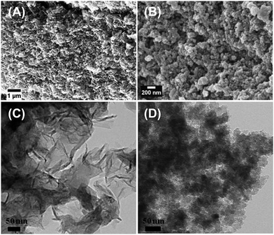 | ||
| Fig. 6 SEM and TEM images of carbon structures prepared via second annealing process in the presence of iron catalyst (A and C), and in the absence of iron catalyst (B and D). | ||
The combination of magnetic moment and large π-system with acceptable porosity suggests that the current materials could be attractive for water purification, particularly for the removal of organics.45,58 Many organic molecules such as dyes or aromatics are toxic, persistent in the environment and non-biodegradable.59 Physical adsorption is an efficient and attractive way to overcome this issue for wastewater treatment.60 Indeed, many carbon materials that have shown effective dye adsorption43,45,59 and Fig. 5 and Table 1 clearly show that the current material is comparable to (and in fact better than some) other carbon materials used for dye removal both in terms of capacity and equilibration time. Although clearly not made via a “green” or “sustainable” process as such, the material is interesting from an environmental application perspective. The OLG nanocomposites combine the advantages of mesoporosity, graphitic surface structure, and magnetic moment making it a comparatively cheap (although still far too expensive for the developing countries) and simple material for water remediation. Upscaling of the materials synthesis, replacement of the still rather const-intensive imidazolium IL with a cheaper, e.g. ammonium-based, IL, and optimization of the water treatment process as such will, however, be necessary prior to commercialization.
Conclusion
The current report describes a general approach towards mesoporous oligo-layer Fe3C/graphite nanoflakes from a renewable monomer, fructose, under ionothermal conditions using the IL [Bmim][FeCl4] as “all-in-one” solvent–reactant–catalyst. The composites are efficient adsorbents for the removal of RB from aqueous solution and can be isolated by magnetic separation with a permanent magnet. Via acid etching, the iron carbide particles can be removed leaving pure mesoporous OLG materials behind. These can be dispersed in hydrophobic solvents such as toluene. Overall, the ionothermal carbonization of renewable raw materials such as the approach demonstrated here may in the future allow the large-scale synthesis of tailormade adsorbents or dispersible (and thus solution processable) oligo-layer graphite with potential application in electronics or sensing.Experimental
IL synthesis
[Bmim][FeCl4] was prepared as described before61 by mixing equimolar amounts of [Bmim][Cl] (2 g, 11.5 mmol) and FeCl3·6H2O (3.16 g, 11.7 mmol) in a round-bottom flask for 30 min. at room temperature while stirring, which results in a two phase mixture (a bottom, brown oily liquid layer and a top water layer). After separating the oily phase from the water layer, the resulting [Bmim][FeCl4] was dried in a vacuum oven at 60 °C overnight. 1H NMR (DMSO-d6, ppm relative to TMS): 9.08 (s, 1H), 7.75 (d, 1H), 7.68 (d, 1H), 4.15 (t, 2H), 3.84 (s, 3H), 1.76 (m, 2H), 1.26 (m, 2H), 0.92 (t, 3H). Elemental analysis: calc. for C8H15Cl4FeN2: C 28.52%, H 4.49%, N 8.32%. Found: C 28.49%, H 4.58%, N 8.24%. Raman: 330 cm−1 (Fe–Cl vibration), 1024 and 1410 cm−1 ([Bmim]+ cation).Carbon ionogel synthesis
D-Fructose was purchased from Sigma-Aldrich® and used without further purification. 3.0 g of fructose was dispersed in 8 mL of [Bmim][FeCl4] at room temperature (fructose is not soluble in the IL at r.t.) The mixtures were loaded into PTFE lined autoclaves and treated at 180 °C for 5 hours. The resulting carbon ionogels were dried overnight at 60 °C.Nanoflake synthesis
Oligo-layer graphite/iron carbide nanoflakes were synthesized by direct carbonization of the carbon ionogels by heating the carbon ionogels in an oven under N2 flow at a heating rate of 10 K min−1 to 750 °C and hold 4 h. The iron/iron carbide nanoparticles within the carbon matrix were removed via soaking in 1 M HCl (aq) solution for 48 h under stirring.Characterization
Scanning electron microscopy (SEM) images were acquired on a LEO 1550 with Everhard–Thornley secondary electron and in-lens detectors. Transmission Electron Microscopy (TEM) and HRTEM were done on a FEI Cs-corrected Titan 80–300 microscope operated at 300 kV with a Gatan energy filter. The Raman spectrometer (Kaiser Optical) was equipped with a frequency-doubled Nd:YAG 532 nm laser. Nitrogen sorption isotherms were measured at 77 K on a Quadrachrome Adsorption Instrument (Quantachrome Instruments). Sample was dried at 120 °C for 12 h prior to nitrogen sorption analysis. UV-vis spectra were recorded on a Perkin-Elmer Lambda 25 UV-vis spectrometer at room temperature.Adsorption test
8 mL of an aqueous Rhodamine B solution with an initial concentration of 25 mg L−1 were mixed with 6 mg of hybrid material. The mixtures were shaken for various amounts of time at room temperature. Concentrations vs. adsorption times were determined via UV/vis spectroscopy. The adsorbed time for isotherm was controlled at 120 min.Acknowledgements
The Max Planck Institute of Colloids and Interfaces (Colloid Chemistry Department) and the University of Potsdam are acknowledged for financial support.References
- A. K. Geim and K. S. Novoselov, Nat. Mater., 2007, 6, 183–191 CrossRef CAS PubMed.
- Z. Y. Sun, N. N. Dong, K. P. Xie, W. Xia, D. Konig, T. C. Nagaiah, M. D. Sanchez, P. Ebbinghaus, A. Erbe, X. Y. Zhang, A. Ludwig, W. Schuhmann, J. Wang and M. Muhler, J. Phys. Chem. C, 2013, 117, 11811–11817 CAS.
- X. Y. Qi, C. L. Tan, J. Wei and H. Zhang, Nanoscale, 2013, 5, 1440–1451 RSC.
- J. U. Park, S. Nam, M. S. Lee and C. M. Lieber, Nat. Mater., 2012, 11, 120–125 CrossRef CAS PubMed.
- D. R. Kauffman and A. Star, Analyst, 2010, 135, 2790–2797 RSC.
- B. F. Machado and P. Serp, Catal. Sci. Technol., 2012, 2, 54–75 CAS.
- X. H. Li, S. Kurasch, U. Kaiser and M. Antonietti, Angew. Chem., Int. Ed., 2012, 51, 9689–9692 CrossRef CAS PubMed.
- P. F. Fulvio, P. C. Hillesheim, J. C. Bauer, S. M. Mahurin and S. Dai, J. Mater. Chem. A, 2013, 1, 59–62 CAS.
- M. Z. Cai, D. Thorpe, D. H. Adamson and H. C. Schniepp, J. Mater. Chem., 2012, 22, 24992–25002 RSC.
- Q. B. Zheng, B. Zhang, X. Y. Lin, X. Shen, N. Yousefi, Z. D. Huang, Z. G. Li and J. K. Kim, J. Mater. Chem., 2012, 22, 25072–25082 RSC.
- K. S. Kim, Y. Zhao, H. Jang, S. Y. Lee, J. M. Kim, K. S. Kim, J. H. Ahn, P. Kim, J. Y. Choi and B. H. Hong, Nature, 2009, 457, 706–710 CrossRef CAS PubMed.
- L. Colombo, X. S. Li, B. Y. Han, C. Magnuson, W. W. Cai, Y. W. Zhu and R. S. Ruoff, Graphene, Ge/III–V, and Emerging Materials for Post-Cmos Applications 2, 2010, vol. 28, pp. 109–114 Search PubMed.
- M. Losurdo, M. M. Giangregorio, P. Capezzuto and G. Bruno, Phys. Chem. Chem. Phys., 2011, 13, 20836–20843 RSC.
- T. Kato and R. Hatakeyama, ACS Nano, 2012, 6, 8508–8515 CrossRef CAS PubMed.
- J. Zhang, P. A. Hu, X. N. Wang, Z. L. Wang, D. Q. Liu, B. Yang and W. W. Cao, J. Mater. Chem., 2012, 22, 18283–18290 RSC.
- M. Wang, S. K. Jang, W. J. Jang, M. Kim, S. Y. Park, S. W. Kim, S. J. Kahng, J. Y. Choi, R. S. Ruoff, Y. J. Song and S. Lee, Adv. Mater., 2013, 25, 2746–2752 CrossRef CAS PubMed.
- C. M. Chen, Q. Zhang, J. Q. Huang, W. Zhang, X. C. Zhao, C. H. Huang, F. Wei, Y. G. Yang, M. Z. Wang and D. S. Su, J. Mater. Chem., 2012, 22, 13947–13955 RSC.
- Y. J. Zhang, K. Fugane, T. Mori, L. Niu and J. H. Ye, J. Mater. Chem., 2012, 22, 6575–6580 RSC.
- X. f. liu, C. Giordano and M. Antonietti, Small, 2013, 10, 193–200 CrossRef PubMed.
- R. D. Rogers and K. R. Seddon, Science, 2003, 302, 792–793 CrossRef PubMed.
- Z. L. Xie, M. L. Feng, B. Tan and X. Y. Huang, CrystEngComm, 2012, 14, 4894–4901 RSC.
- J. R. Li, Z. L. Xie, X. W. He, L. H. Li and X. Y. Huang, Angew. Chem., Int. Ed., 2011, 50, 11395–11399 CrossRef CAS PubMed.
- Z. Ma, J. H. Yu and S. Dai, Adv. Mater., 2010, 22, 261–285 CrossRef CAS PubMed.
- J. P. Paraknowitsch, J. Zhang, D. S. Su, A. Thomas and M. Antonietti, Adv. Mater., 2010, 22, 87–92 CrossRef CAS PubMed.
- R. Gobel, Z. L. Xie, M. Neumann, C. Gunter, R. Lobbicke, S. Kubo, M. M. Titirici, C. Giordano and A. Taubert, CrystEngComm, 2012, 14, 4946–4951 RSC.
- J. Y. Yuan, C. Giordano and M. Antonietti, Chem. Mater., 2010, 22, 5003–5012 CrossRef CAS.
- J. Ma, X. Duan, J. Lian and W. Zheng, CrystEngComm, 2013, 14, 832–836 RSC.
- W. J. Xiao, Z. Y. Sun, S. Chen, H. Y. Zhang, Y. F. Zhao, C. L. Huang and Z. M. Liu, RSC Adv., 2012, 2, 8189–8193 RSC.
- Z. L. Xie, R. J. White, J. Weber, A. Taubert and M. M. Titirici, J. Mater. Chem., 2011, 21, 7434–7442 RSC.
- S. K. Panja and S. Saha, RSC Adv., 2013, 3, 14495–14500 RSC.
- R. Gobel, R. J. White, M. M. Titirici and A. Taubert, Phys. Chem. Chem. Phys., 2012, 14, 5992–5997 RSC.
- Z. Q. Li, C. J. Lu, Z. P. Xia, Y. Zhou and Z. Luo, Carbon, 2007, 45, 1686–1695 CrossRef CAS PubMed.
- T. Ungar, J. Gubicza, G. Ribarik, C. Pantea and T. W. Zerda, Carbon, 2002, 40, 929–937 CrossRef CAS.
- J. Schwan, S. Ulrich, V. Batori, H. Ehrhardt and S. R. P. Silva, J. Appl. Phys., 1996, 80, 440–447 CrossRef CAS PubMed.
- S. Gurunathan, J. W. Han, V. Eppakayala and J. H. Kim, Int. J. Nanomed., 2013, 8, 1015–1027 CrossRef PubMed.
- S. Brunauer, P. H. Emmett and E. Teller, J. Am. Chem. Soc., 1938, 60, 309–319 CrossRef CAS.
- S. Kubo, R. Demir-Cakan, L. Zhao, R. J. White and M. M. Titirici, ChemSusChem, 2010, 3, 188–194 CrossRef CAS PubMed.
- G. Ertl, H. Knözinger and J. Weitkamp, Handbook of Heterogeneous Catalysis, VCH, Weinheim, 1997, pp. 191–207.
- H. Colfen and M. Antonietti, Angew. Chem., Int. Ed., 2005, 44, 5576–5591 CrossRef PubMed.
- D. S. Li, M. H. Nielsen, J. R. I. Lee, C. Frandsen, J. F. Banfield and J. J. De Yoreo, Science, 2012, 336, 1014–1018 CrossRef CAS PubMed.
- M. Niederberger and H. Colfen, Phys. Chem. Chem. Phys., 2006, 8, 3271–3287 RSC.
- N. G. Shang, P. Papakonstantinou, M. McMullan, M. Chu, A. Stamboulis, A. Potenza, S. S. Dhesi and H. Marchetto, Adv. Funct. Mater., 2008, 18, 3506–3514 CrossRef CAS.
- T. B. Wang, L. Liang, R. W. Wang, Y. Q. Jiang, K. F. Lin and J. M. Sun, Adsorption, 2012, 18, 439–444 CrossRef CAS.
- Z. M. Chen, Z. L. Xue, L. Chen, Z. R. Geng, R. C. Yang, L. Y. Chen and Z. L. Wang, New J. Chem., 2013, 37, 3731–3736 RSC.
- Z. G. Geng, Y. Lin, X. X. Yu, Q. H. Shen, L. Ma, Z. Y. Li, N. Pan and X. P. Wang, J. Mater. Chem., 2012, 22, 3527–3535 RSC.
- J. K. Liu, H. Q. Cao, J. P. Xiong and Z. Y. Cheng, CrystEngComm, 2012, 14, 5140–5144 RSC.
- G. K. Ramesha, A. V. Kumara, H. B. Muralidhara and S. Sampath, J. Colloid Interface Sci., 2011, 361, 270–277 CrossRef CAS PubMed.
- Y. Yan, H. P. Sun, P. P. Yao, S. Z. Kang and J. Mu, Appl. Surf. Sci., 2011, 257, 3620–3626 CrossRef CAS PubMed.
- L. Li, S. X. Liu and T. Zhu, J. Environ. Sci., 2010, 22, 1273–1280 CrossRef CAS.
- J. Anandkumar and B. Mandal, J. Hazard. Mater., 2011, 186, 1088–1096 CrossRef CAS PubMed.
- K. Kadirvelu, C. Karthika, N. Vennilamani and S. Pattabhi, Chemosphere, 2005, 60, 1009–1017 CrossRef CAS PubMed.
- Y. G. Zhang and J. Y. G. Chan, Energy Environ. Sci., 2010, 3, 408–417 CAS.
- J. P. Paraknowitsch and A. Thomas, Macromol. Chem. Phys., 2012, 213, 1132–1145 CrossRef CAS.
- M. Tunckol, J. Durand and P. Serp, Carbon, 2012, 50, 4303–4334 CrossRef CAS PubMed.
- S. Hayashi and H. O. Hamaguchi, Chem. Lett., 2004, 33, 1590–1591 CrossRef CAS.
- K. Bica, S. Leder and P. Gaertner, Curr. Org. Synth., 2011, 8, 824–839 CAS.
- K. Bica and P. Gaertner, Eur. J. Org. Chem., 2008, 3453–3456 CrossRef CAS.
- J. Y. Chen, Y. M. Hao, Y. Liu and J. J. Gou, RSC Adv., 2013, 3, 7254–7258 RSC.
- H. L. Parker, A. J. Hunt, V. L. Budarin, P. S. Shuttleworth, K. L. Miller and J. H. Clark, RSC Adv., 2012, 2, 8992–8997 RSC.
- P. K. Malik, J. Hazard. Mater., 2004, 113, 81–88 CrossRef CAS PubMed.
- Z. L. Xie and A. Taubert, ChemPhysChem, 2011, 12, 364–368 CrossRef CAS PubMed.
Footnote |
| † Electronic supplementary information (ESI) available. See DOI: 10.1039/c4ra05146g |
| This journal is © The Royal Society of Chemistry 2014 |

