DOI:
10.1039/C4RA07228F
(Paper)
RSC Adv., 2014,
4, 43270-43277
Molecular level controlled fabrication of highly transparent conductive reduced graphene oxide/silver nanowire hybrid films†
Received
17th July 2014
, Accepted 2nd September 2014
First published on 3rd September 2014
Abstract
Due to the scalability of production and the convenience in processing, graphene oxide (GO) has become an important precursor for the fabrication of transparent conductive films (TCFs). Developing a method to reduce the high contact resistance between the GO sheets, which is mainly due to the presence of a huge number of intersheet junctions, is the key for these applications. Here, we demonstrate a method of molecular level controlled fabrication of hybrid TCFs composed of 1-dimensional (1D) silver nanowires (Ag NWs) and 2-dimensional (2D) reduced graphene oxide (rGO) sheets. The ultra-large graphene oxide (UL-GO) sheets were transferred onto the quartz substrate via the Langmuir–Blodgett (L–B) method and then covered with Ag NW by the spin-coating method. The hybrid film was then reduced by chemical reduction using hydrazine hydrate. Upon varying the amount of Ag NW, the reduced UL-GO/Ag NW hybrid films show low sheet resistance ranging 13 to 48 Ω sq−1 with optical transmittance ranging from 71.9% to 91.2%. The direct current (DC) to optical conductivity ratio of the hybrid films can reach up to 81, which is comparable to that of indium tin oxide (ITO).
1. Introduction
Transparent conductive films (TCFs) have been widely used in photovoltaic and opto-electronic devices, such as solar cells, flat displays, touch panels, solid state lightning and optical communication devices.1,2 Indium tin oxide (ITO) and fluorine tin oxide (FTO) are the main materials to produce TCFs due to their high optical transparency and electrical conductivity.3 However, the poor compatibility with organic materials,4–6 brittle ceramic structure,7,8 and the growing cost of indium seriously limit the use of ITO and FTO for TCFs, especially in large-area applications.8,9 Graphene, an atom-thick layer of sp2-hybridized carbon atoms,10 has excellent transport properties with charge carrier mobility values in excess of 20![[thin space (1/6-em)]](https://www.rsc.org/images/entities/char_2009.gif) 000 cm2 V−1 s−1 at room temperature and absorbs about 2.3% of visible light.11,12 These unique properties make graphene an alternative candidate for TCFs.13 Due to the scalability of production and the convenience in processing, graphene oxide (GO) has become an important precursor for the fabrication of TCFs.14,15 However, as the presence of a huge number of intersheet junctions with high contact resistance between the GO sheets, the resistances of GO based TCFs are still higher than ITO.16
000 cm2 V−1 s−1 at room temperature and absorbs about 2.3% of visible light.11,12 These unique properties make graphene an alternative candidate for TCFs.13 Due to the scalability of production and the convenience in processing, graphene oxide (GO) has become an important precursor for the fabrication of TCFs.14,15 However, as the presence of a huge number of intersheet junctions with high contact resistance between the GO sheets, the resistances of GO based TCFs are still higher than ITO.16
Hybrid films, whose properties can be improved due to the synergy effect between individual components, can overcome the shortcomings of the single-component TCFs.17–20 Many 1D conducting fillers, such as carbon nanotubes and silver nanowires (Ag NWs), have been actively investigated as candidates to reduce high contact resistance between the graphene sheets.19,21–26 Moreover, depending on the composition, the hybrid TCFs may exhibit diversified functionalities. The feature reveals possibilities for developing the next generation multicomponent and multifunctional TCFs.20 However, the use of carbon nanotube as hybrid component is hampered by the inevitable defects on the tubes, bundling between tubes, and the mixture of metallic and semiconducting carbon nanotubes. Recently, it is shown that hybridization with silver nanowires is a promising approach to increase the electrical conductivity of graphene based TCFs.21,27–30 The graphene/Ag NW hybrid films have been fabricated via several well-established techniques including spin-coating,20 dip coating27 or spray coating31 method. However, these methods are hard to control the GO structure, which will influence the final opto-electronic properties. The Langmuir–Blodgett (L–B) method, which is known to be the only technique that can realize the deposition of GO sheets in a layer-by-layer manner, can accurately control the GO surface structure in molecular level.
Here, we demonstrated a way of molecularly controlled fabrication of hybrid TCFs composed of 1-dimensional (1D) Ag NWs and 2D reduced ultra-large GO (rUL-GO) sheets. The UL-GO sheets were transferred onto the quartzes substrate via L–B method and then covered with Ag NW by spin-coating method. The hybrid film was then reduced by chemical reduction using hydrazine hydrate. Upon varying the amount of Ag NW, the conductivity ratio can reach up to 81, which is comparable to that of ITO.
2. Experimental
2.1 Preparation of graphene oxide and screening process
A mixture of 5 g of natural graphite (NG) flakes (Asbury Graphite Mills, US) and 150 mL sulfuric acid (H2SO4, 95.5–96.5%, General Chemical) was stirred in a round bottom flask at a speed of 200 rpm. After 50 mL of fuming nitric acid (Fisher) was added, the mixture was kept at room temperature and stirred for 24 h. Then, 200 mL of de-ionized (DI) water was poured slowly into the mixture. To obtain graphite intercalation compound (GIC), the resultant mixture was washed for three times by using DI water, followed by centrifugation and drying at 60 °C for 24 h. The dried GIC powder was then thermally expanded at 1050 °C for 15 s to obtain expanded graphite (EG). A mixture of 1 g of EG and 200 mL of H2SO4 was stirred in a three neck flask. 10 g of potassium permanganate was added to the mixture drop wise with stirring. The mixture was then kept at 60 °C and stirred for 24 h. After the solution was transferred into an ice bath, 200 mL of DI water and 50 mL of hydrogen peroxide (H2O2) were poured slowly into the mixture and the colour turned into light brown. The GO particles were washed and centrifuged with HCl solution three times, then centrifuged again and washed with DI water until the pH of the solution became about 5 to 6. The obtained GO particles thereby were diluted using DI water (∼1 mg mL−1) and delaminated by gentle shaking. Polydispersity in size, the as-prepared GO sheets need to be grouped into different size grades through three runs of centrifugation for efficient using. Typically, the unsorted, as-prepared GO solution was initially centrifuged at 8000 rpm for 40 min, dividing into supernatant and precipitates, while the supernatant was labeled as small GO (S-GO). The collected precipitate was dispersed for the second run of centrifugation at 8000 rpm for 25 min, producing supernatant and precipitate. The supernatant was designated as large GO while the precipitate was dispersed in water again and used for the third run of centrifugation at 4000 rpm for 25 min, producing very large GO (supernatant) and UL-GO (precipitate).
2.2 Preparation of GO/Ag nanowire hybrid film
Quartz slides were used as substrate for L–B deposition of UL-GO films. 15 mm × 15 mm square slides were washed in an acetone bath under ultrasonication to remove any organic contamination. They were then immersed in a piranha solution (volH2SO4:volH2O2 = 7:3) for 1 h, followed by rinsing with DI water and drying in a vacuum oven for 30 min. For L–B assembly of GO, the L–B trough (Medium LB Deposition Trough, KSV-NIMA Co, Ltd.) was carefully cleaned with ethanol and then filled with water–methanol mixture. GO solution was slowly spread onto the water surface dropwise using a glass syringe. The solution was spread with a speed of 100 μL min−1 up to a total of 7 mL and the GO monolayer formed thereby was stabilized for about 20 min before compression. The surface pressure was monitored using a tensiometer attached to a Wilhelmy plate while the GO sheets were compressed by moving barriers at the speed of 10 mm min−1. A GO film with faint brown color could be observed by the end of the compression. The GO monolayer was transferred to a substrate at various points during the compression by vertically dipping the substrate into the trough and slowly pulling it up at a speed of 0.1 mm min−1. Then, a spin-coater (KW 4A, SIYOUYEN Co, Ltd.) was used to transfer the Ag NWs on to the as-prepared GO films. The Ag NW (Nanjing XFNANO Materials Tech Co., Ltd. Average diameter ∼ 90 nm, average length ∼ 200 μm) was dispersed in alcohol and ultrasonicated at low energy (12 W, 55 kHz) for 5 min before deposited it onto the substrate. Then the substrate was accelerated at 200 rpm s−1 for 10 s to make the solution uniformly distributed and then at 1000 rpm s−1 for 15 s to spread the solution. Then the films were thermally annealed at 60 °C in vacuum oven for 30 min to evaporate the residual solvent in the thin films. After dried in the vacuum oven, the GO/Ag NW hybrid films were reduced by hydrazine hydrate (N2H4, 85%, AR) vapor. The hybrid film was kept in the N2H4 vapor at 90 °C for 10 min until they turned to be light grey.
2.3 Characterizations
Scanning electron microscope (SEM, FEI CO., LTD Quanta FEG) was used to characterize the structure and morphology of GO, Ag NW and GO/Ag NW TCFs. The tapping-mode atomic force microscope (AFM, Park Systems, PSIA Incorporation) was employed to evaluate the surface morphology of GO and GO/Ag NW TCFs films. The molecular structure of GO sheets, Ag NW and GO/Ag NW films was characterized by high resolution transmission electron microscopy (TEM, FEI TGF 30). The sheet resistance of the films was measured by the four-point probe method (Scientific Equipment & Services). In order to reduce the contact resistance between the probes and the film surface, the four contact points were coated with silver paste. The elemental compositions and the assignments of the carbon peaks were characterized by the X-ray photoelectron 85 spectroscopy (XPS, PHI5600 Physical Electronics), which was equipped with a monochromatic Al Kα X-ray source operated in a residual vacuum of 5 × 10⁻⁹ Torr. The UV-Vis spectra of the transparency of the TCFs were measured by Perkin Elmer Lambda 750 UV-Vis spectrometer.
3. Results and discussion
3.1 L–B assembly of GO
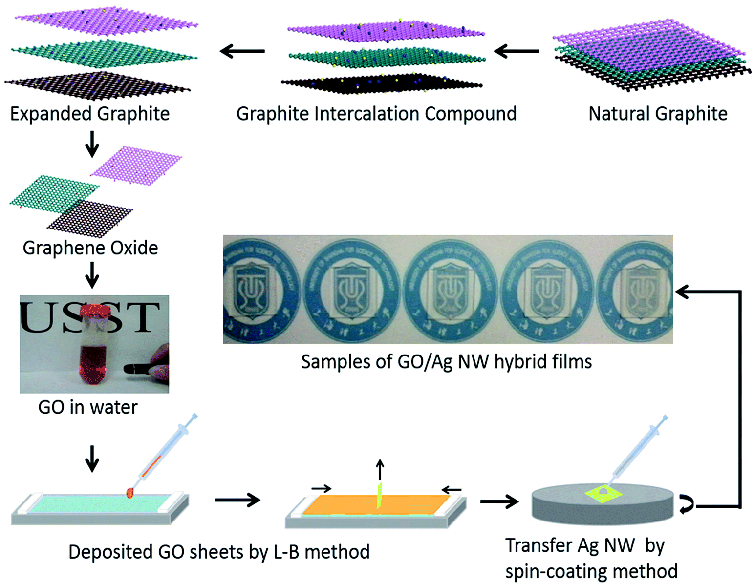
The method used to prepare monolayer GO sheets is similar to our previous studies,14,32,33 which is schematically shown in Fig. 1. The surface of as-received NG flake is very smooth (Fig. 2a), while the EG shows a “fluffy” structure after intercalation and shock exfoliation (Fig. 2b), which is mainly due to the greatly increased d-spacing and disrupted structure. Fig. 2c shows that the UL-GO sheets are very soft with a paper liked structure. The dimensions of UL-GO and S-GO are several tens and several μm. UL-GO was chosen for the TCF fabrication due to the less junctions between GO sheets. The high resolution TEM image of UL-GO sheets (Fig. 2e) and the corresponding selected area electron diffraction (SAED) pattern (Fig. 2f), further confirms that the GO sheets possess an amorphous structure.
 |
| | Fig. 1 Flow chart for the synthesis of GO/Ag NW hybrid films. | |
 |
| | Fig. 2 SEM images of NG, EG and GO. (a) SEM image of NG surface; (b) SEM image of fluffy EG surface; (c and d) SEM images of UL-GO (c) and S-GO (d); (e) TEM image of UL-GO edge; (f) diffraction image of UL-GO sheet. | |
L–B technique was then performed to produce GO films. The typical surface pressure–area (π–A) curves (Fig. 3a) indicate that UL-GO and S-GO have different curve structure variation under mechanical compression. Since UL-GO sheets tend to be much softer than S-GO,32,34 UL-GO possesses higher surface pressure than S-GO at the phase transition points. The π–A curves of 3 cycles (Fig. 3b) compression and expansion show that the UL-GO sheets are quite stable on the water surface. The small gaps between the continued cycles indicate that there is a loss of small amount of materials after each cycle as the UL-GO sheets might wrinkled together or dropped into the water.14
 |
| | Fig. 3 (a) Isotherm plots of S-GO and UL-GO. (b) Three sequent compression/expansion cycles were performed for UL-GO. | |
3.2 Hybrid with Ag NW
After the UL-GO sheets were deposited onto the surface of quartz, different amount of Ag NWs (0.25 to 1.25 mg) were further deposited on top of UL-GO film by spin-coating method. Fig. 4a shows a typical AFM image of UL-GO/Ag NW hybrid film. The height profiles taken along the red line in the AFM image show that the Ag NW has a diameter of ∼100 nm. The height profile along the green line indicates that the thickness of the UL-GO sheet is about 2 nm, which is attributed to the presence of oxygen functionalities on the sheets.35,36 The SEM (Fig. 4c) and TEM (Fig. 5a) images further confirm that the diameter of the Ag NW is about ∼100 nm, while the length is several micrometres. As schematically shown in Fig. 4d, the strong interaction between UL-GO sheets and Ag NWs might benefit the electrical conductivity due to the tighter bonding between Ag NWs.37 Since the rUL-GO layer acts as both efficient electron transport pathway and adhesive layer for Ag NW, the hybrid film possesses excellent opto-electrical performance. Fig. 4e shows the optical image of the UL-GO/Ag NW hybrid film with a higher Ag NW density (1.25 mg).
 |
| | Fig. 4 AFM, SEM and optical images of the UL-GO/Ag NW hybrid films. (a) AFM images of the hybrid film. (b) Cross section height profiles of Ag NW and GO in (a) indicated by red and green line respectively. (c) SEM image of the UL-GO/Ag NW hybrid films with a lower Ag NW density (0.005 mg). (d) Schematic structure of the UL-GO/Ag NW hybrid film and (e) the optical image of the UL-GO/Ag NW hybrid film with a higher Ag NW density (1.25 mg). | |
 |
| | Fig. 5 TEM images of Ag NW (a and b) and energy-dispersive X-ray spectroscopy (c) of UL-GO/AgNW hybrid film. | |
The TEM images of UL-GO/Ag NW hybrid film (Fig. 5a and b) show the GO sheets and the Ag NWs are well connected. Due to the strong attractive force between UL-GO and Ag NW,38 the contact resistance between Ag NWs can be greatly reduced. It is also shown that the Ag NW is absorbed on the UL-GO sheet (Fig. 5c), which is confirmed by energy-dispersive X-ray spectroscopy (EDX) spectrum. The EDX spectrum in Fig. 5c shows C signal peak and O signal peak, which are the main constituent elements in UL-GO sheets.
3.3 Post-treatment of the hybrid films
As the absence of percolating pathways among sp2 carbon clusters, the atomically thin plane presents large amount of oxygen-containing functional groups, which would severely hinders charge transport.15,39,40 Hence, the efficient reduction to restore the sp2 conjugated graphene network become the prerequisite for the use of GO as a TCF. N2H4 has been reported to be an effective reducing agent that can remove the oxygen-containing functional groups on GO sheets.20,35,41 Thus, N2H4 vapor was performed to reduce the hybrid films without destroying the hybrid structure.
To better understand their surface chemistries that are directly correlated to the optical and the electrical properties, the XPS analysis was performed to evaluate the elemental compositions and the functionalities of the hybrid films. Fig. 6 shows the general spectra and curve fitting of C1s spectra of UL-GO and rUL-GO/Ag NW hybrid film. The general spectrum of the rUL-GO/Ag NW hybrid films (Fig. 6c) shows several Ag signal around 600 and 400 eV, which are mainly originate from Ag NW. The C1s signal mainly consisted of five different chemically shifted components that can be deconvoluted into: C![[double bond, length as m-dash]](https://www.rsc.org/images/entities/char_e001.gif) C (sp2) in aromatic rings at ∼284.9 eV; C–C (sp3) in aromatic rings at ∼285.6 eV; C–O (hydroxyl and epoxy) at ∼287.1 eV; CO (carbonyl) at 288.1 eV; and –O–CO (carboxyl) at ∼290.0 eV. After reduction, the sp2 component increased from 36.5% to 74.7% and the sp3 component decreased from 21.5% to 13%. The component of C–O, CO and –O–CO groups were reduced from 21.8%, 13.6%, 6.6% to 4.2%, 4%, 4.1% respectively (see Table SI1†), confirming the removal of oxygenated functional groups by N2H4 vapor.
C (sp2) in aromatic rings at ∼284.9 eV; C–C (sp3) in aromatic rings at ∼285.6 eV; C–O (hydroxyl and epoxy) at ∼287.1 eV; CO (carbonyl) at 288.1 eV; and –O–CO (carboxyl) at ∼290.0 eV. After reduction, the sp2 component increased from 36.5% to 74.7% and the sp3 component decreased from 21.5% to 13%. The component of C–O, CO and –O–CO groups were reduced from 21.8%, 13.6%, 6.6% to 4.2%, 4%, 4.1% respectively (see Table SI1†), confirming the removal of oxygenated functional groups by N2H4 vapor.
 |
| | Fig. 6 XPS analysis of the UL-GO and rUL-GO/Ag NW hybrid films. (a and b) XPS general spectra and curve fitting of C1s spectra of UL-GO. (c and d) XPS general spectra and curve fitting of C1s spectra of the rUL-GO/Ag NW hybrid film. | |
3.4 Opto-electrical properties
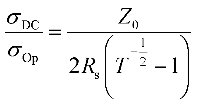
Fig. 7a and b show the optical transmittance of rUL-GO/Ag NW hybrid TCFs as a function of the Ag NW content. As expected, the transmittance of the film decreased with increasing Ag NW contents. The increase in Ag NW concentrations increased both the back reflection and absorption of light, resulting in the reduction in transparency. The optical transmittance at 550 nm decrease from 91.2% to 71.9% by increasing the concentration of Ag NW from 0.25 to 1.25 mg. Fig. 7c presents the sheet resistance of the pure Ag NW film and rUL-GO/Ag NW hybrid films containing various Ag NW contents. It is shown that the rUL-GO/Ag NW TCFs display conductivities superior to those of pure Ag NW films. To evaluate whether these properties remain stable after exposure to ambient air, the sheet resistance were measured after 12 months later. It is noteworthy that the sheet resistance increased 1–2 Ω sq−1 12 months later showing an excellent stability. A possible reason for the increasing sheet resistance is that the electrical performance would be affect by the water moisture adsorbed by rGO layers. It did not bring much influence to the hybrid film as the GO layer is only few micron. The DC to optical conductivity ratio has been proposed to compare the opto-electrical properties of TCFs.3 The relationship between transmittance (T) and sheet resistance (Rs) is controlled by the conductivity ratio σDC/σOp, using the equation.| |
 | (1) |
where σDC is DC conductivity; σOp is optical conductivity, Z0 = 377 Ω is the impedance of free space. A high σDC/σOp ratio represents a high transmittance and a low sheet resistance, and thus high opto-electrical properties of TCFs, and vice versa. Fig. 7d shows the calculated σDC/σOp values for graphene based hybrid TCFs. The σDC/σOp of the TCFs made from UL-GO sheets with L–B method and Ag NW with spin-coating method in this study is 81, which is much higher than other methods preparing TCFs made from normal sized GO hybrid with Ag NW or Ag/Au nanoparticle (Ag NP) or carbon nanotube (CNT).13,16,20,27,42–46 The σDC/σOp of the 1.25 mg Ag NW film is 59.7 (21.8 Ω sq−1, with 76.3% transparency), and the one layer rGO film is about 0.631 (9.85 kΩ sq−1 with 94.2% transparency). Once they are combined together, the σDC/σOp can reach up to 81, showing the synergy mechanism of the hybrid films. Several reasons may responsible for the outstanding opto-electrical properties: (i) rUL-GO sheets decreased the high intersheet contact resistance by reducing the amount of intersheet junctions between GO sheets, (ii) depositing the UL-GO sheets in the layer-by-layer manner by the L–B method, which can accurately control the UL-GO surface structure in molecular level and optimize the structure of the hybrid films, and (iii) the present of rUL-GO sheets produce more conducting paths for carriers.
 |
| | Fig. 7 Transmittance of Ag NW film and UL-GO/Ag NW hybrid film. (a) and (b) show the optical transmittance of rUL-GO/Ag NW hybrid TCFs as a function of the Ag NW content. (c) Sheet resistance of the pure Ag NW film, rUL-GO/Ag NW hybrid films and the hybrid film exposure for 12 months later containing various Ag NW contents. (d) Optical conductivity ratio comparison of current work and the reported data. | |
4. Conclusions
In summary, we fabricated a highly conductive rUL-GO/Ag NW hybrid TCFs via a molecular level controlled process. The UL-GO films was transferred onto the quartzes substrate by L–B method, while the Ag NW monolayer was further deposited by spin-coating to obtain transparent conductive hybrid films. The rUL-GO layer acts as both the efficient electron transport pathway and the adhesive layer for Ag NW simultaneously. Upon chemical reduction by N2H4 vapor, the rUL-GO/Ag NW hybrid TCFs showed excellent opto-electrical performance. It is believed that the rUL-GO/Ag NW hybrid TCFs can be used as an alternative to ITO for emerging opto-electronic devices.
Acknowledgements
The authors gratefully acknowledge financial support from NSFC (51102170, 51272157), Shanghai Pujiang Talent Project (13PJ1406400), China Postdoctoral Science Foundation (2012M520912), Shanghai Postdoctoral Science Foundation (13R21415500), Shanghai Committee of Science and Technology (12JC1406900), the Alexander von Humboldt Foundation, and the Innovation Fund Project For Graduate Student of Shanghai (JWCXSL1401).
Notes and references
- J. K. Wassei and R. B. Kaner, Mater. Today, 2010, 13, 52–59 CrossRef CAS
 .
. - S. P. Pang, Y. Hernandez, X. L. Feng and K. Mullen, Adv. Mater., 2011, 23, 2779–2795 CrossRef CAS PubMed .
- S. De and J. N. Coleman, ACS Nano, 2010, 4, 2713–2720 CrossRef CAS PubMed .
- J. van de Lagemaat, T. M. Barnes, G. Rumbles, S. E. Shaheen, T. J. Coutts, C. Weeks, I. Levitsky, J. Peltola and P. Glatkowski, Appl. Phys. Lett., 2006, 88, 233503–233509 CrossRef PubMed .
- H. F. Liang and R. G. Gordon, J. Mater. Sci., 2007, 42, 6388–6399 CrossRef CAS PubMed .
- S. Y. Ju, A. Facchetti, Y. Xuan, J. Liu, F. Ishikawa, P. D. Ye, C. W. Zhou, T. J. Marks and D. B. Janes, Nat. Nanotechnol., 2007, 2, 378–384 CrossRef CAS PubMed .
- T. Sekitani, H. Nakajima, H. Maeda, T. Fukushima, T. Aida, K. Hata and T. Someya, Nat. Mater., 2009, 8, 494–499 CrossRef CAS PubMed .
- D. J. Lipomi, M. Vosgueritchian, B. C. K. Tee, S. L. Hellstrom, J. A. Lee, C. H. Fox and Z. N. Bao, Nat. Nanotechnol., 2011, 6, 788–792 CrossRef CAS PubMed .
- M. P. de Jong, D. P. L. Simons, M. A. Reijme, L. J. van IJzendoorn, A. W. D. van der Gon, M. J. A. de Voigt, H. H. Brongersma and R. W. Gymer, Synth. Met., 2000, 110, 1–6 CrossRef CAS .
- H. V. Rizo, I. M. Gullon and M. Terrones, ACS Nano, 2012, 6, 4565–4572 CrossRef PubMed .
- A. B. Kuzmenko, E. van Heumen, F. Carbone and D. van der Marel, Phys. Rev. Lett., 2008, 100, 117401–117409 CrossRef CAS .
- R. R. Nair, P. Blake, A. N. Grigorenko, K. S. Novoselov, T. J. Booth, T. Stauber, N. M. R. Peres and A. K. Geim, Science, 2008, 320, 1308 CrossRef CAS PubMed .
- I. N. Kholmanov, C. W. Magnuson, A. E. Aliev, H. Li, B. Zhang, J. W. Suk, L. L. Zhang, E. Peng, S. H. Mousavi, A. B. Khanikaev, R. Piner, G. Shvets and R. S. Ruoff, Nano Lett., 2012, 12, 5679–5683 CrossRef CAS PubMed .
- Q. B. Zheng, B. Zhang, X. Y. Lin, X. Shen, N. Yousefi, Z. D. Huang, Z. G. Li and J. K. Kim, J. Mater. Chem., 2012, 22, 25072–25082 RSC .
- J. P. Zhao, P. S. Feng, W. C. Ren, L. B. Gao and H. M. Cheng, ACS Nano, 2010, 4, 5245–5252 CrossRef CAS PubMed .
- D. H. Shin, K. W. Lee, J. S. Lee, J. H. Kim, S. Kim and S. H. Choi, Nanotechnology, 2014, 25, 125701–125707 CrossRef PubMed .
- V. C. Tung, J. Kim, L. J. Cote and J. X. Huang, J. Am. Chem. Soc., 2011, 133, 9262–9265 CrossRef CAS PubMed .
- Y. Zhu, Z. Z. Sun, Z. Yan, Z. Jin and J. M. Tour, ACS Nano, 2011, 5, 6472–6479 CrossRef CAS PubMed .
- C. W. Jeong, P. Nair, M. Khan, M. Lundstrom and M. A. Alam, Nano Lett., 2011, 11, 5020–5025 CrossRef CAS PubMed .
- I. N. Kholmanov, M. D. Stoller, J. Edgeworth, W. Lee, H. F. Li, J. Lee, C. Barnhart, J. R. Potts, R. Piner, D. Akinwande, J. E. Barrick and R. S. Ruoff, ACS Nano, 2012, 6, 5157–5163 CrossRef CAS PubMed .
- C. H. Liu and X. Yu, Nanoscale Res. Lett., 2011, 6, 1–8 Search PubMed .
- Z. Wu, Z. Chen, X. Du, J. M. Logan, J. Sippel, M. Nikolou, K. Kamaras, J. R. Reynolds, D. B. Tanner, A. F. Hebard and A. G. Rinzler, Science, 2004, 305, 1273–1276 CrossRef CAS PubMed .
- A. R. Rathmell, S. M. Bergin, Y. L. Hua, Z. Y. Li and B. J. Wiley, Adv. Mater., 2010, 22, 3558–3563 CrossRef CAS PubMed .
- D. Azulai, T. Belenkova, H. Gilon, Z. Barkay and G. Markovich, Nano Lett., 2009, 9, 4246–4249 CrossRef CAS PubMed .
- G. Gruner, J. Mater. Chem., 2006, 16, 3533–3539 RSC .
- L. B. Hu, D. S. Hecht and G. Gruner, Chem. Rev., 2010, 110, 5790–5844 CrossRef CAS PubMed .
- H. W. Tien, S. T. Hsiao, W. H. Liao, Y. H. Yu, F. C. Lin, Y. S. Wang, S. M. Li and C. C. M. Ma, Carbon, 2013, 58, 198–207 CrossRef CAS PubMed .
- X. Y. Zeng, Q. K. Zhang, R. M. Yu and C. Z. Lu, Adv. Mater., 2010, 22, 4484–4488 CrossRef CAS PubMed .
- J. Y. Lee, S. T. Connor, Y. Cui and P. Peumans, Nano Lett., 2008, 8, 689–692 CrossRef CAS PubMed .
- L. B. Hu, H. S. Kim, J. Y. Lee, P. Peumans and Y. Cui, ACS Nano, 2010, 4, 2955–2963 CrossRef CAS PubMed .
- I. K. Moon, J. I. Kim, H. Lee, K. Hur, W. C. Kim and H. Lee, Sci. Rep., 2013, 3, 1–7 Search PubMed .
- Q. B. Zheng, Z. G. Li and J. H. Yang, RSC Adv., 2013, 3, 923–929 RSC .
- Q. B. Zheng, Y. Geng, S. J. Wang, Z. G. Li and J. K. Kim, Carbon, 2010, 48, 4315–4322 CrossRef CAS PubMed .
- Q. B. Zheng, W. H. Ip, X. Y. Lin, N. Yousefi, K. K. Yeung, Z. G. Li and J. K. Kim, ACS Nano, 2011, 5, 6039–6051 CrossRef CAS PubMed .
- G. Eda, G. Fanchini and M. Chhowalla, Nat. Nanotechnol., 2008, 3, 270–274 CrossRef CAS PubMed .
- D. S. Hecht, L. B. Hu and G. Irvin, Adv. Mater., 2011, 23, 1482–1513 CrossRef CAS PubMed .
- A. Tao, F. Kim, C. Hess, J. Goldberger, R. R. He, Y. g. Sun, Y. N. Xia and P. D. Yang, Nano Lett., 2003, 3, 1229–1234 CrossRef CAS .
- Y. Li, H. Li, K. Zhang and K. M. Liew, Carbon, 2012, 50, 566–576 CrossRef CAS PubMed .
- G. Eda, Y. Y. Lin, C. Mattevi, H. Yamaguchi, H. A. Chen, I. S. Chen, C. W. Chen and M. Chhowalla, Adv. Mater., 2010, 22, 505–509 CrossRef CAS PubMed .
- L. F. Shi, J. H. Yang, Z. D. Huang, J. Li, Z. H. Tang, Y. Li and Q. B. Zheng, Appl. Surf. Sci., 2013, 276, 437–446 CrossRef CAS PubMed .
- L. J. Cote, F. Kim and J. X. Huang, J. Am. Chem. Soc., 2009, 131, 1043–1049 CrossRef CAS PubMed .
- Y. S. Yun, D. H. Kim, B. Kim, H. H. Park and H. J. Jin, Synth. Met., 2012, 162, 1364–1368 CrossRef CAS PubMed .
- X. Zhang, X. b. Yan, J. t. Chen and J. p. Zhao, Carbon, 2014, 69, 437–443 CrossRef CAS PubMed .
- S. H. Domingues, I. N. Kholmanov, T. Kim, J. Kim, C. Tan, H. Chou, Z. A. Alieva, R. Piner, A. J. G. Zarbin and R. S. Ruoff, Carbon, 2013, 63, 454–459 CrossRef CAS PubMed .
- J. Gao, W. Y. Wang, L. J. Chen, X. Y. Hu and H. Z. Geng, Appl. Surf. Sci., 2013, 277, 128–133 CrossRef CAS PubMed .
- H. W. Tien, Y. L. Huang, S. Y. Yang, J. Y. Wang and C. C. M. Ma, Carbon, 2011, 49, 1550–1560 CrossRef CAS PubMed .
Footnote |
| † Electronic supplementary information (ESI) available. See DOI: 10.1039/c4ra07228f |
|
| This journal is © The Royal Society of Chemistry 2014 |
Click here to see how this site uses Cookies. View our privacy policy here.