Graphene for advanced Li/S and Li/air batteries
Haegyeom Kim†
a,
Hee-Dae Lim†
a,
Jinsoo Kim
a and
Kisuk Kang
*abc
aDepartment of Materials Science and Engineering, Seoul National University, 599 Gwanak-ro, Gwanak-gu, 151-742 Seoul, Republic of Korea. E-mail: matlgen1@snu.ac.kr; Fax: +82-2-885-9671; Tel: +82-2-880-7088
bResearch Institute of Advanced Materials (RIAM), Seoul National University, 151-742 Seoul, Republic of Korea
cCenter for Nanoparticle Research, Institute for Basic Science (IBS), Seoul National University, Seoul 151-742, Republic of Korea
First published on 7th August 2013
Abstract
Li/S and Li/air cells have attracted much recent attention as potential successors to lithium ion batteries because of their exceptionally high energy density compared with current battery technology. Although the two new battery systems have the potential to satisfy the demand for a significant leap forward in energy storage technology, there remain significant problems to be addressed, including poor cycle stability and low rate capability for practical applications. To address these issues, much research effort has been invested. In particular, graphene, with its high surface area combined with catalytic properties, is considered to be a key potential material to advance Li/S and Li/air battery technology. Indeed, recent research into graphene has led to substantial performance improvements of Li/S and Li/air batteries. In this review, we describe recent achievements in Li/S and Li/air cells that have been facilitated by the application of graphene, together with the electrochemical reaction mechanisms and major issues facing both Li/S and Li/air batteries.
1 Introduction
Increasing demands for large-scale energy storage have led to growing research interest in developing high-performance energy storage systems.1–7 The current prevailing lithium-ion battery (LIB) technology has seen widespread commercial use in providing high energy density for portable devices; however, the energy aspect is still insufficient for large-scale applications such as electric vehicles or smart grids. There is, therefore, significant interest in the development of next-generation batteries, or so-called post-LIB batteries, which can overcome the limitations of current LIB technology.Li/S and Li/air batteries are two of the most promising post-LIB battery candidates because of their potential to dramatically increase the energy density.8–16 Reversible oxidation and reduction of sulfur or oxygen forms the basis of the reactions at the cathode in Li/S and Li/air batteries, respectively, differently from those in conventional LIBs, where reversible redox reactions of heavy transition metals are used.12,17–20 In Li/S batteries, elemental sulfur can directly react with two Li's without the requirement for heavy transition metals, delivering high energy density of 2567 W h kg−1.12 Similarly, in Li/air batteries, one molecule of O2 can react with two Li's, delivering the energy density of 3505 W h kg−1.12,20 These energy densities are significantly higher than those of conventional LIBs.20
However, several serious problems remain in the development of Li/S and Li/air batteries.21,22 These include poor cycle life, low energy efficiency, and slow charge/discharge reaction, which have so far prevented practical applications of these devices from appearing. The underlying reasons for these issues in Li/S batteries are: (i) dissolution of polysulfides, intermediate reaction products, in the electrolyte; (ii) large volume change between the elemental sulfur (S) and lithiated phase (Li2S); and (iii) slow kinetics originating from the low electronic conductivity of the reaction products.21 In Li/air batteries, the important issues arise from (i) the hysteresis in the voltage during the charge and discharge cycles resulting in low energy efficiency; (ii) slow reaction kinetics in the formation and decomposition of the insulating lithiated phase (Li2O2);23,24 and (iii) chemical instability of oxygen radicals. Recent studies have shown that many of these issues can be resolved or at least mitigated by the proper design of electrode materials and architecture. A significant breakthrough in the design of the electrode is required for both Li/S and Li/air battery systems.
Graphene, a two-dimensional material consisting of a “carbon honeycomb”,25,26 is a promising promoter in improving the electrochemical performance of both Li/S and Li/air batteries. For Li/S batteries, the large surface area, high mechanical strength, and exceptionally high electrical conductivity of the graphene matrix27–31 are beneficial not only to increase the overall electronic conductivity of the electrode to mitigate the sluggish kinetics, but also to buffer the large volume change between the delithiated S and lithiated Li2S phases. In Li/air battery systems, graphene contains potentially a vast active area for harvesting discharge products, which may lead to even higher capacity. It was also demonstrated that the graphene can enhance the kinetics in Li/air batteries as a catalyst in itself or as an effective support for other catalysts.13,32–35 The efficient formation/decomposition of discharge products could enhance the cycle stability and the round-trip efficiency of Li/air batteries. In this respect, there have been extensive investigations using graphene-based electrode materials in Li/S and Li/air cells, which could significantly improve the electrochemical performance.32,36–41
In this feature article, we review the recent progress in the development of Li/S and Li/air cells incorporating graphene. The electrochemical reaction mechanisms and major issues in Li/S and Li/air cells will be briefly introduced, then a survey of graphene-based electrodes will be followed with an emphasis on Li/S and Li/air battery applications. Finally, concluding remarks outlining future challenges and prospects will be provided.
2 Energy storage in Li/S batteries
2.1 Energy storage mechanism and challenges in Li/S batteries
The working principle of Li/S batteries is based on the reversible oxidation and reduction of sulfur. The overall reaction mechanism is described as follows:17,42,43| S8 + 16Li+ + 16e− ↔ 8Li2S |
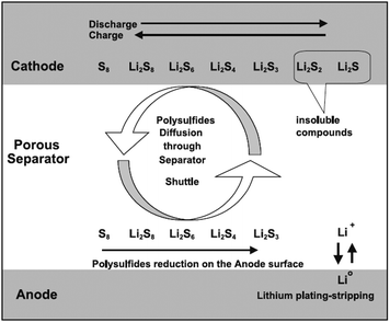 | ||
| Fig. 1 Schematic illustrating the principle of operation of Li/S batteries. Reprinted with permission.42 Copyright 2004, Elsevier. | ||
In addressing these issues, proper design of the electrode structure is one of the key factors with the potential to solve problems. The ideal electrode should have the following characteristics:
(i) Effective trapping of soluble polysulfides to minimize the shuttle effect and loss of active material
(ii) A large conductive surface area to mitigate the effects of the deposition of an insulating Li2S layer
(iii) A flexible structure that is capable of accommodating a large volume change.
In this respect, there have been numerous efforts to improve the electrochemical performance of Li/S batteries by developing nanostructured cathodes using carbon-based materials.3,45–47 A carbonaceous matrix may confine polysulfides and at the same time provide an electronically conducting pathway. Graphene is arguably one of the most promising candidates for such a conductive matrix because of the high surface area, superior electronic conductivity, and high mechanical strength.20,26 Consequently, graphene has been widely investigated for use in Li/S batteries.36–39,48–52 In the following sections, we will review graphene-based cathodes in Li/S batteries depending on the strategy of how the graphene was used.
2.2 Sulfur-coated graphene
Coating the graphene surface with sulfur has demonstrated that graphene can improve the electrochemical performance of Li/S batteries by enhancing the charge transfer kinetics. Wang et al.48 simply mixed elemental sulfur and graphene by mechanical mixing and heating to coat sulfur on the graphene. The simple mixing increased the capacity from 800 mA h g−1 to 1100 mA h g−1. However, the mechanical mixing and heating method could not result in uniform distribution of sulfur on the graphene, thus, the sulfur was not effectively coupled with the graphene, and sulfur coating based on a solution process was more effective.53–55 A uniform sulfur/graphene composite has been prepared by using graphene oxide (GO) and sulfur-containing compounds, including Na2SO3 and Na2S (Fig. 2).53 The GO was converted to sulfur-modified graphene oxide (GS) due to the reaction between GO and S2− when Na2SO3 and Na2S were added. The addition of sulfuric acid resulted in uniformly dispersed sulfur on the graphene surface by the oxidation of S2− and the restoration of GS. This approach could lead to a stable discharge capacity of about 800 mA h g−1 at a specific current of 312 mA g−1 (Fig. 2c). The total mass loading of the electrode was in the range 1.0–2.0 mg cm−2, and the sulfur content in the electrode was ∼50% by weight. Furthermore, a specific capacity of ∼492 mA h g−1 was achieved even for a current rate of ∼1670 mA g−1. The improved electrochemical performance of this composite has been attributed to the following factors: (i) extensive sulfur distribution on the large-surface graphene, which increases the usability of the sulfur active material; and (ii) the high electronic conductivity (∼1.30 S cm−1), which facilitates the charge transfer reaction. Nevertheless, the coating of the graphene with sulfur could not effectively prevent the “shuttle” phenomenon regardless of the synthetic routes, which is another critical problem deteriorating the cycle life of Li/S batteries. In the sulfur coated graphene electrode, sulfur is exposed to the electrolyte and is at the risk of dissolution of polysulfides upon discharge. To reduce the shuttle effect in a Li/S cell, it is necessary to trap polysulfides either chemically or mechanically.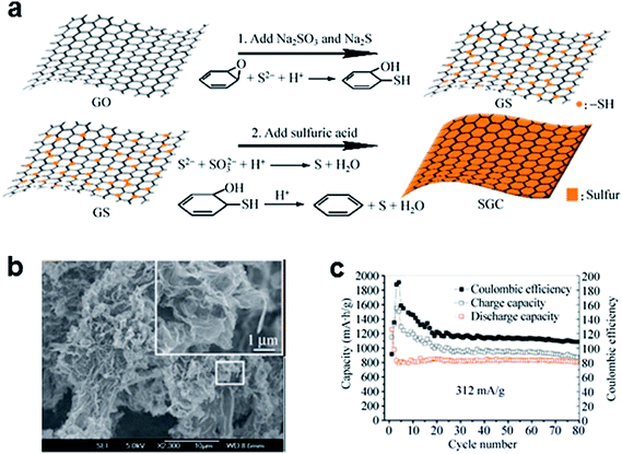 | ||
| Fig. 2 (a) Schematic representation of the synthesis of sulfur-coated graphene composites. (b) Scanning electron microscopy (SEM) image of sulfur-coated graphene composites. (c) Cycling performance of sulfur-coated graphene composites at a current rate of 312 mA g−1. Reproduced with permission.53 Copyright 2012, Springer. | ||
2.3 Graphene matrix filled with elemental sulfur
Filling the porous graphene matrix with elemental sulfur has been reported to effectively confine sulfur and polysulfides in the electrode, as shown in Fig. 3.50 A thermally exfoliated graphene nanosheet–sulfur (TG–S) sample was prepared by mixing and heating the thermally exfoliated graphene nanosheets (TG) and the sulfur. To further confine sulfur, TG–S was coated again with reduced graphene oxide (RGO). A suspension of TG–S and Na2S2O3 in ethanol and distilled water (1![[thin space (1/6-em)]](https://www.rsc.org/images/entities/char_2009.gif) :
:![[thin space (1/6-em)]](https://www.rsc.org/images/entities/char_2009.gif) 9 volume ratio) was added to the GO solution, followed by the addition of hydrochloric acid (RGO–TG–S). Because both the functional group and the sp2 carbon in the RGO have strong chemical interactions with sulfur, the RGO could bind to the sulfur, forming a RGO–TG–S nanocomposite. Typical two-plateau behavior of the sulfur cathode corresponding to the formation of long-chain lithium polysulfides at 2.3 V and short-chain Li2S2 and Li2S at 2.1 V has been shown in both TG–S and RGO–TG–S samples (Fig. 3b).50,56 However, the diffusion of soluble polysulfides could be effectively retarded by the RGO coating. The discharge capacity retention increased from 54.9% for TG–S to 71.9% for RGO–TG–S at a current rate of 200 mA g–1 based on the discharge capacities at the 2nd and 100th cycles. The total mass loading of the electrode was in the range 0.9–1.0 mg cm−2. The reported sulfur content of the electrode was 44.1% by weight.
9 volume ratio) was added to the GO solution, followed by the addition of hydrochloric acid (RGO–TG–S). Because both the functional group and the sp2 carbon in the RGO have strong chemical interactions with sulfur, the RGO could bind to the sulfur, forming a RGO–TG–S nanocomposite. Typical two-plateau behavior of the sulfur cathode corresponding to the formation of long-chain lithium polysulfides at 2.3 V and short-chain Li2S2 and Li2S at 2.1 V has been shown in both TG–S and RGO–TG–S samples (Fig. 3b).50,56 However, the diffusion of soluble polysulfides could be effectively retarded by the RGO coating. The discharge capacity retention increased from 54.9% for TG–S to 71.9% for RGO–TG–S at a current rate of 200 mA g–1 based on the discharge capacities at the 2nd and 100th cycles. The total mass loading of the electrode was in the range 0.9–1.0 mg cm−2. The reported sulfur content of the electrode was 44.1% by weight.
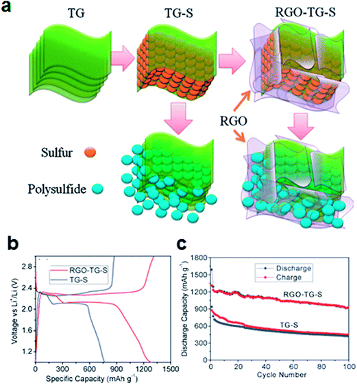 | ||
| Fig. 3 (a) Schematic of graphene filled with sulfur particles. At the edges of the graphene, the polysulfides can diffuse from between the graphene sheets. Following combination with the graphene coating layers, polysulfides can be confined in the structure. (b) Charge/discharge profiles and (c) cyclability of the composites at a current density of 200 mA g−1.50 Reproduced from ref. 50 with permission from The Royal Society of Chemistry. | ||
Similarly, sandwich-type graphene/sulfur composite with a Nafion polymer coating has been shown to improve the cycle stability and rate capability of Li/S batteries.38 The sandwich-like structure was able to immobilize soluble polysulfides and accommodate a large volume change during battery cycling. The reported sulfur content in the Nafion-coated sandwich-type graphene/sulfur composite was 71.8% by weight, and the total sulfur mass ratio in the electrode was 57.44% by weight. This sandwich-type graphene/sulfur composite could deliver a capacity of 950 mA h g−1 at the initial discharge, and a 79.4% capacity retention was shown after 50 cycles at a current rate of 168 mA g−1. The improved electrochemical performance was attributed to the high conductivity of graphene and the effective trapping of soluble polysulfides in the structure.
2.4 Graphene-wrapped sulfur particles
As a direct approach to encapsulate polysulfides, a graphene-wrapping method was proposed by Wang et al., in which a sulfur particle is wrapped by graphene (Fig. 4).36 Sulfur particles were coated with a poly-ethyleneglycol (PEG)-containing surfactant and wrapped by graphene decorated with carbon black. The surfactant-coated sulfur particles were fabricated by reacting Na2S2O3 with HCl along with Triton X-100 surfactant, which acted as a capping agent limiting the size of the sulfur particles. The carbon black was added to increase the electronic conductivity of the final composite material. Sub-micron-diameter sulfur particles were then coated with graphene. The sulfur content in the as-synthesized material was 70% by weight. This structure was able to trap soluble polysulfides in the matrix, while allowing the sulfur particles to conduct electrical charge. As a result, the graphene-wrapped sulfur particles could deliver a high specific capacity of 750 mA h g−1 at the initial discharge at a current of 334 mA g−1, which decreased to 600 mA h g−1 after 10 cycles. The capacity decreased only by 13% after an additional 90 cycles.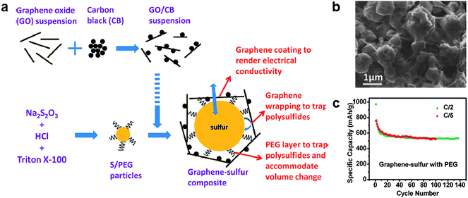 | ||
| Fig. 4 (a) Schematic of the synthesis of a graphene/sulfur composite with a proposed structure. (b) SEM image of the graphene/sulfur composite. (c) Cycle stability of the composite.36 Reprinted with permission from ref. 36. Copyright 2011 American Chemistry Society. | ||
A simpler method to prepare graphene-wrapped sulfur particles using an oil/water system was reported by Zhang et al. (Fig. 5).57 For preparing graphene wrapped sulfur particles, GO was dispersed in water to form an aqueous suspension using sonication. Then, an oil-phase solution containing sulfur and carbon disulfide (CS2) was added and mixed via ultrasonication. After evaporation of the CS2, hydrazine hydrate (N2H4·H2O) was added to reduce the GO to RGO. Using this process, sub-micron-diameter sulfur particles were effectively encapsulated by graphene sheets as shown in Fig. 5b and c. The reported sulfur content in the as-fabricated material was ∼65% by weight. The graphene encapsulation could contribute to trapping soluble polysulfides in the matrix to reduce the shuttle effect, and was able to provide an electron transport path at the same time. At a current rate of 1675 mA g−1, a discharge capacity of approximately 622 mA h g−1 was observed after 60 cycles (85.8% capacity retention with >95% coulombic efficiency). In addition, a discharge capacity of 478.7 mA h g−1 at the 60th cycle was achieved with the high current rate ∼of 6700 mA g−1. The discharge capacity increased gradually with the cycle number during the initial several cycles. This behavior was explained by considering that graphene-wrapped sulfur particles were not sufficiently soaked in the electrolyte. As the electrochemical reaction proceeded, more sulfur particles in the (relatively closed) matrix became exposed to the electrolyte.
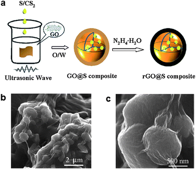 | ||
| Fig. 5 (a) Schematic of the synthesis of graphene-wrapped sulfur particles. (b and c) SEM images of the composites.57 Reproduced from ref. 57 with permission from The Royal Society of Chemistry. | ||
2.5 Sulfur captured in graphene hydrogel
Another approach to trap soluble polysulfides was reported by Ji et al. in 2011 and Ding et al. in 2013.37,58 They confined polysulfides in nanopores of graphene which formed in the hydrogel as shown in Fig. 6.58 An RGO hydrogel was prepared using the hydrothermal method, where the graphene underwent self-assembly through π–π stacking interactions constructing an RGO hydrogel column. A porous network with pore sizes ranging from sub-micron dimensions to several micrometers was created. The hydrogel columns were soaked in a KOH solution to fill the void space. Following annealing at 800 °C, activated graphene with nanopores was obtained. The reaction proceeded by the activation of carbon as 6KOH + C ↔ 2K + 3H2 + 2K2CO3, followed by decomposition of K2CO3. Sulfur was encapsulated into the activated graphene matrix by heating a mixture of activated graphene and sulfur particles. The strong affinity of sulfur for carbon was the driving force for diffusing liquid sulfur into the space between layers of activated graphene and nanopores. The as-synthesized composite contained 50–67% sulfur by weight and could deliver a specific capacity of 927 mA h g−1 at the initial cycle at a current rate of 1675 mA g−1. A specific capacity of 685 mA h g−1 (74% of the initial capacity) was retained after 100 cycles. It was claimed that the sulfur was not absorbed onto the surface, but was perfectly confined within the nanopores. Therefore, the electrochemical reactions between Li ions and elemental sulfur could be spatially restricted to the nanopores of the graphene (Fig. 6b). Good electrical contact of sulfur with the conductive graphene matrix allowed rapid electron transfer. In addition, good accessibility to the electrolyte was achieved owing to the porous network. Together, it enhanced the utilization of the sulfur to deliver a high specific capacity. The nanopores could act as “micro-reactors” for electrochemical reactions that effectively trap elemental sulfur and polysulfides during cycling. Finally, the graphene matrix could accommodate the volume change, preventing the isolation of active materials during repeated electrochemical reactions.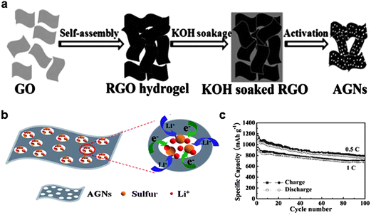 | ||
| Fig. 6 (a) Schematic showing the preparation route of activated graphene through self-assembly of graphite oxide, ion diffusion, and chemical activation. (b) Proposed scheme for the constrained electrochemical reaction process of the activated graphene/sulfur composite. (c) Cycle stability of the activated graphene/sulfur composite.58 Reproduced from ref. 58 with permission from The Royal Society of Chemistry. | ||
2.6 Self-supporting graphene/sulfur paper
A conventional electrode is composed of electrochemically active materials and inactive elements such as binder and current collectors. Polymer binders are widely used to stably hold the active materials/conductive carbon on the current collector, and current collector allows effective transport of electrons to them.59 However, the use of the electrochemically inactive components reduces overall energy density of the battery. Thereby, it is desirable to develop an electrode free of inactive components without compensation of the performance. Recently, Jin et al. developed a flexible self-standing graphene/sulfur paper electrode through wet-chemical methods (Fig. 7).60 For sample preparation, graphene sheets were first dispersed in de-ionized water by sonication, then Na2S2O3·5H2O was added and the resulting mixture was filtered. Typical graphene/sulfur paper electrodes had a thickness in the range 40–60 μm and a density in the range 0.4–0.6 g cm−3. The sulfur content of the paper electrode was 60% by weight. The graphene/sulfur paper electrodes exhibited a discharge capacity of 700 mA h g−1 during the first cycle, and maintained 83% of the initial capacity after 100 cycles at a current rate of 167.5 mA g−1. The gravimetric energy density was 1200 W h kg−1 relative to the sulfur mass, and 804 W h kg−1 considering the total mass of the electrode after 100 cycles. Accessibility of the electrolyte into the active material was enhanced and the volume change during cycling could be accommodated by the large free volume in the paper electrode. The graphene matrix served as both a conductive framework and a support for the sulfur particles.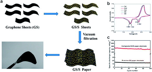 | ||
| Fig. 7 (a) Schematic and photograph of flexible self-supporting graphene/sulfur composites. (b) Cyclic voltammogram curves of a graphene/sulfur paper electrode at 0.5 mV s−1 in the range 1–3 V. (c) Cycling performance of primitive graphene paper and a graphene/sulfur composite at 167.5 mA g−1.60 Reproduced from ref. 60 with permission from The Royal Society of Chemistry. | ||
In summary, hybridization of sulfur with conductive graphene matrix could effectively inhibit the shuttle effect and accommodate the large volume change during battery cycling, and therefore, could show excellent capacity retention (Fig. 8). The physical and chemical encapsulating of elemental sulfur was more effective than simple mixing of sulfur with graphene. The development of nanostructured graphene/sulfur composites led to significant progress in performances of Li/S batteries. Among various approaches, capturing sulfur in graphene hydrogel showed promising electrochemical performances in terms of capacity and cycle stability, which are important for practical applications (Fig. 8b). However, a low sulfur content in the composite materials is still problematic in practical applications because the low sulfur contents can result in low volumetric energy density in practical cells. Furthermore, sulfur encapsulation often requires complex multi-step synthetic routes, which can be disadvantageous for mass production. We believe that the cost-effective sulfur encapsulation with high sulfur content is the key to move a step forward for practical applications.
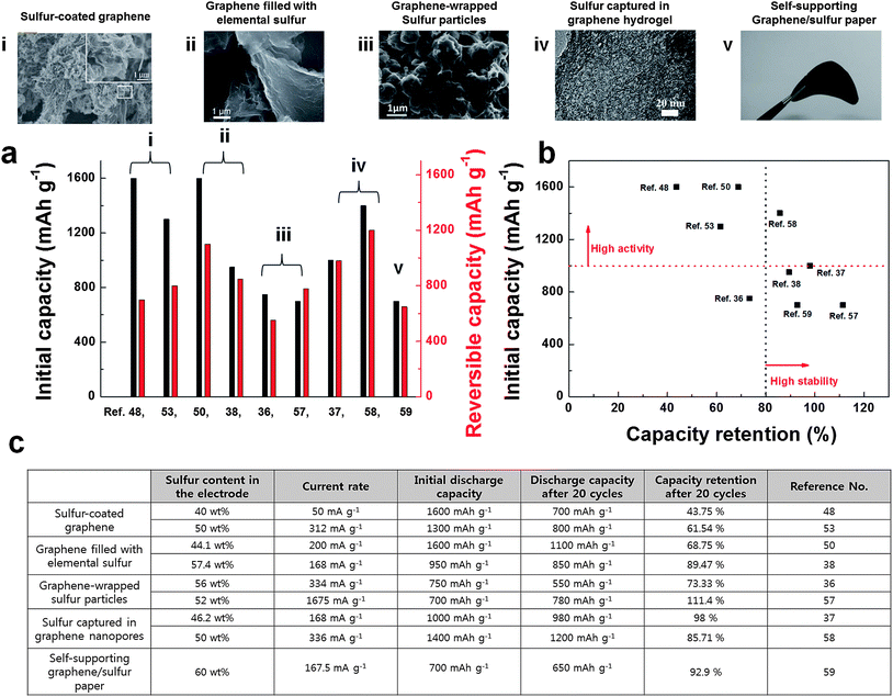 | ||
| Fig. 8 (a) Electrochemical performances of various sulfur/graphene composite materials. Initial capacities and reversible capacities of sulfur/graphene composite materials are plotted. Note that the reversible capacity is the 20th cycle's capacity value. (b) Electrochemical activities and cycle stability of sulfur/graphene composite materials are summarized. (c) Summary of electrochemical performances and their measurement conditions of sulfur/graphene composite materials. | ||
Chemical and morphological structures of graphene are also important factors to improve the performance of Li/S batteries. It is well known that the presence of graphene edges significantly affects the reactivity, electron transfer, and Li diffusion properties.61–63 The edges in graphene can promote electron transfer and Li diffusion, which can significantly improve the performance of the electrochemical cells. In this respect, it is believed that a proper design of the edge structure of graphene can further enhance the electrochemical activity and rate capability of Li/S batteries.
3 Energy storage in Li/air batteries
3.1 Energy storage mechanism and challenges in Li/air batteries
There has been considerable recent interest in Li/air batteries due to their exceptionally high energy density. Since Li/air batteries exploit the direct reaction between lithium ions and oxygen molecules in ambient air without any heavy transition metals or crystal frameworks, in theory, an energy density of 3500 W h kg−1 is possible, which is the highest of all types of Li batteries.20,64–66 The electrochemical reaction is based on the reversible reaction of lithium to form lithium oxides as follows:15,67–69| 2Li+ + O2 + 2e− ↔ Li2O2 (2.96 V) |
| 4Li+ + O2 + 4e− ↔ 2Li2O (2.92 V) |
Following the first report of the Li/air system by Abraham and Jiang,71 the challenges faced in advancing such a battery system have been taken up by numerous research groups. Briefly, there are three major challenges affecting the electrochemical performance of Li/air cells. These can be summarized as follows:
(i) The stability of electrolyte: the first prototype Li/air cells used carbonate-based electrolytes from conventional LIBs, such as propylene carbonate (PC) and ethylene carbonate/dimethyl carbonate (EC/DMC). However, it was soon revealed that carbonate-based electrolytes were prone to attack from oxygen radicals, resulting in the decomposition and deterioration of the electrolyte during cycling.19,72,73 While alternative electrolytes such as tetraethylene glycol dimethyl ether (TEGDME),74,75 dimethoxyethane (DME),73,76 and dimethyl sulfoxide (DMSO)77,78 were investigated, they still exhibited limited stability in prolonged cycles.79 The electrolyte stability remains as one of the major issues for Li/air batteries.80–82
(ii) The air-electrode morphology: since the solid-state discharge products, Li2O2, are directly formed and deposited on the air-electrode surface,83,84 the morphology and the amount of discharge product are dependent on the shape of the air-electrode.85–87 The relationship between the electrochemical properties and the type of air-electrode (such as Super P, Ketjen Black, CNT, gold or graphene) has been widely studied.41,65,88–90 The surface area and pore size of the air-electrode are the primary factors affecting the electrochemical properties, thus, the optimization of the air-electrode morphology is an active area of research.
(iii) Catalysts: the catalysts in the air-electrode can contribute to the rechargeability of Li/air cells. After the full discharge of a Li/air cell, the non-conductive Li2O2 discharge products cover up the electrode surface,91,92 which leads to the considerably higher polarization during charging than in LIBs (in the range of 1.5–2 V overpotential). The large overpotential results in not only the unacceptably low energy efficiency, but also the deterioration of the electrolyte and the carbon substrate.83,93,94 While the clear mechanism has not been revealed yet, it has been shown that the use of catalysts can significantly lower the OER overpotential. Consequently, the development of suitable catalysts to lower the high polarization is required.
In this section, we will review the recent progress in the use of graphene in Li/air batteries according to their role in the enhancement of the performance.
3.2 Graphene as a constituent of air-electrodes
In the early stages of development of Li/air cells, conventional carbon materials that have been used as the conductive agents in LIBs, such as Super P and Super S, were employed as the main constituent of the air-electrode.88,91,95 Various carbon materials have been investigated,85,96 since they are light and highly conductive. It was revealed that the discharge capacity usually increases with the surface area of carbon materials. Ketjen Black (KB) with its large specific surface area of approximately 1200 m2 g−1 could deliver a high discharge capacity.79,85,90 Graphene with its largest specific surface area, 2630 m2 g−1,97 could, in principle, not only provide a large effective area for reaction sites, but also facilitate the accessibility of oxygen and Li ions. Li et al. successfully demonstrated that graphene in itself could deliver a high discharge capacity of approximately 8705 mA h g−1 in Li–O2 batteries.41 It is remarkably larger compared with other types of carbon substrates, such as BP-2000 (1909 mA h g−1) and Vulcan XC-72 (1053 mA h g−1) as shown in Fig. 9. It was found that the discharge products grew on the graphene surface, in particular at the edges of the graphene sheets, as shown in Fig. 9d and e.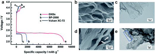 | ||
| Fig. 9 (a) Discharge/charge performance of Li/air cells with GNSs, BP-2000, and Vulcan XC-72 cathodes at a current of 75 mA g−1. SEM and TEM images of GNSs electrodes (b), (c) before and (d), (e) after discharge.41 Reproduced from ref. 41 with permission from The Royal Society of Chemistry. | ||
Graphene has also proved to be a promising constituent of air-electrode in hybrid Li/air systems composed of an organic electrolyte at the anode side and an aqueous electrolyte at the cathode side.20,24,98 Yoo and Zhou have examined graphene nanosheets (GNSs) for the use as air-electrodes in the hybrid Li/air cell whose schematic is shown in Fig. 10.32 Using chemically synthesized graphene with a surface-to-mass ratio of 342.6 m2 g−1, a significant reduction in the overpotential as well as a high capacity could be achieved for hybrid Li/air systems. The reversible reactions of LiOH in the hybrid Li/air cell resulted in a decreased overpotential close to that of 20 wt% Pt/CB during discharge. The presence of dangling σ-bonds (i.e., sp3 hybridized carbon atoms) at the edges of GNSs was suggested as the reason for the reduction of overpotential. Cycling up to 50 cycles was accomplished with the GNS electrode promising the use of graphene in hybrid Li/air cells.
 | ||
| Fig. 10 (a) Schematic showing the structure of a rechargeable Li/air cell based on a GNSs electrode. (b) Discharge curves of 20 wt% Pt/CB, GNSs, and AB at a current density of 0.5 mA cm−2 for 24 hours. (c) Correlation between cycle number and capacity of Li/air cells based on GNSs electrodes. Reproduced with permission from ref. 32. Copyright 2011 American Chemistry Society.32 | ||
The advantage of the morphology of graphene could be further strengthened with the assembly of graphene. Many research groups have attempted to assemble graphene to control the size and distribution of pore in air-electrodes.85,99 Xiao et al. reported an air-electrode consisting of hierarchically porous graphene.40 They designed a porous structure with a large specific surface area to enlarge the triphase regions (i.e., solid–liquid–gas triple point), as shown in the schematic in Fig. 11. The porous framework, comprised of numerous connected nanopores, offered diffusion paths for oxygen to access the inner space of the air-electrode. The increase in the number of reaction sites in the porous framework led to a drastically increased discharge capacity of approximately 15![[thin space (1/6-em)]](https://www.rsc.org/images/entities/char_2009.gif) 000 mA h g−1. It demonstrates that the morphology of the carbon substrate is an important factor determining the electrochemical performance of Li/air cells.
000 mA h g−1. It demonstrates that the morphology of the carbon substrate is an important factor determining the electrochemical performance of Li/air cells.
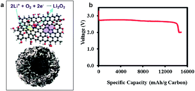 | ||
| Fig. 11 (a) Schematic showing the structure of a functionalized graphene sheet (upper image) with a bimodal porous structure (lower image). (b) Discharge curve of a Li/air cell using the functionalized graphene sheets as the electrode (PO2 = 2 atm). Reprinted with permission from ref. 40. Copyright 2011 American Chemistry Society.40 | ||
Wang et al. also found that a free-standing hierarchically porous carbon (FHPC) structure derived from GO could serve as an effective air-electrode for Li/air cells.89 To ensure the efficient utilization of the carbon substrate, they designed the porous carbon with large void volume, which also provided a freestanding 3D framework. GO was adopted not only as a basic carbon source, but also as a scaffold for the 3D gel in Fig. 12. During discharge, the macroporous tunnels facilitated oxygen diffusion, while the inner small pores provided large tri-phase regions for the formation or decomposition of reaction products. The modified graphene structure delivered a specific capacity of approximately 11![[thin space (1/6-em)]](https://www.rsc.org/images/entities/char_2009.gif) 060 mA h g−1 at a current density of 0.2 mA cm−2, as shown in Fig. 12. Even when the current density increased to 2 mA cm−2, a high capacity of 2000 mA h g−1 could be retained.
060 mA h g−1 at a current density of 0.2 mA cm−2, as shown in Fig. 12. Even when the current density increased to 2 mA cm−2, a high capacity of 2000 mA h g−1 could be retained.
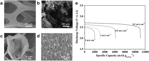 | ||
| Fig. 12 (a) SEM images of pristine nickel foam and (b–d) different magnifications of the as-prepared FHPC electrode. (e) Discharge curves of FHPC electrodes at different current densities in the range 0.2–2.0 mA cm−2.89 Copyright 2012 WILEY-VCH Verlag GmbH & Co. KGaA, Weinheim. | ||
3.3 Graphene as a catalyst
It was reported that the edges of graphene sheets, as well as defects in the graphene, can generally exhibit catalytic activity for OERs and hydrogen evolution reactions (HERs).100–102 Similarly, the possibility of using graphene as a catalyst in Li/air systems has been investigated by many groups. Sun et al. first demonstrated the use of graphene as a catalyst for a Li/air cell using an alkyl carbonate electrolyte (Fig. 13).13 Chemically reduced graphene oxide sheets with a specific surface area of 309 m2 g−1 and a specific pore volume of 0.3666 cm3 g−1 were compared with conventional carbon (Vulcan XC-72 carbon with a specific surface area of approximately 240 m2 g−1 and a specific pore volume of 0.3834 cm3 g−1). While the discharge capacity was not dramatically increased due to the similarity in the specific surface area and pore volume, the graphene electrodes showed a smaller polarization with improved round-trip efficiency. The decreased overpotential was attributed to the catalytic activity of carbon vacancies and defects at the graphene in the formation and decomposition of reaction products. Because defects and edges of graphene can generally exhibit higher reactivity with fast electron transfer compared to bulk graphene sheets, the formation and decomposition of reaction products can preferentially occur at those sites of graphene.61 However, because a carbonate-based electrolyte, which are now known to readily decompose during cycling,19,73 was used in their tests, it is not clear that the graphene acted as an OER catalyst. Nevertheless, graphene was also demonstrated to be catalytically active in aqueous based Li-air cells by several groups,32,33 where a decrease in the overpotential was observed using GNSs in hybrid electrolyte systems.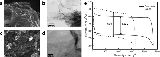 | ||
| Fig. 13 FESEM images of (a) the as-prepared GNSs and (b) commercial Vulcan XC-72 carbon. (c) TEM image of GNSs and (d) HRTEM image of GNSs. (e) Charge/discharge voltage profiles (in the third cycle) of the as-prepared GNSs and Vulcan XC-72 carbon. Capacities are per gram of carbon in the electrode at a current density of (0.1 mA cm−2).13 Copyright 2012, Elsevier. | ||
3.4 Graphene-supported hybrid catalysts
Graphene may also be used as an effective support material for loading catalysts, such as MnO2, Co3O4, SnO2, and Mn3O4.33–35,103–107 Catalysts can be either physically loaded or, more often, chemically grown on the graphene. It was reported that coupling catalyst particles onto the graphene surface resulted in an enhancement of the catalyst activity.37,108,109 The facile formation of a triple-phase boundary in a metal oxide (MOx)/graphene hybrid catalyst was also partly attributed to the enhanced catalytic activity (Fig. 14). MOx/graphene hybrid catalysts were generally synthesized based on the modified Hummers method.110,111 In this method, graphite is oxidized using a strong acid to produce GO, which contains oxygen-containing functional groups, including carbonyl (–CO), hydroxylic (–COH), and carboxylic acid (–COOH) groups on the surface.34,112 Negatively charged functional groups can provide reaction sites for the absorption of positively charged metal ions, such as Mn2+, Co3+, and Sn2+. Subsequently, the metal ions and graphene oxide are reduced, either chemically or using heat treatment, yielding the composite. The adhesion between the graphene and nanoparticles was expected to promote the catalytic activity of the individual particles. A synergistic catalytic effect of graphene and MOx has been reported. Fig. 15 compares various MOx/graphene hybrid catalysts with their morphology and electrochemical performance. Fig. 15a indicates that MnO2 grown on graphene resulted in improved catalytic activity compared with a physical mixture of the two.34 CoMn2O4 nanoparticles grown on graphene was also demonstrated as a catalyst,35 though it exhibited a marginal improvement for ORR and OER (Fig. 15b). On the other hand, MnCo2O4/graphene hybrid catalysts showed better catalytic activity, which was comparable to what has been achieved using Pt/C as shown in Fig. 15c.109 A hybrid Co3O4/graphene catalyst was able to deliver a stable and reversible capacity compared with a cell composed of a simple mixture of Co3O4 and graphene in Fig. 15d.72 The discharge capacities are slightly different for each case due to the different surface areas of the synthesized graphene and catalyst, however, the decreased polarization and the enhanced cyclability were clearly demonstrated with the use of a hybrid catalyst. The electrochemical properties of various metal oxide (MOx)/graphene hybrid catalysts are summarized in Table 1.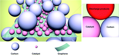 | ||
| Fig. 14 Schematic illustrating of the concept of a hybrid catalyst. Catalyst particles are individually attached to the graphene surface, which assures a large number of active sites for the catalyst.72 Copyright 2013, Elsevier. | ||
 | ||
| Fig. 15 Several types of graphene-supported hybrid catalysts and their corresponding electrochemical profiles. (a) TEM image of a α-MnO2/graphene catalyst and electrochemical profiles using three different catalysts (current density: 200 mA g−1).34 Reproduced from ref. 34 with permission from The Royal Society of Chemistry. (b) Voltage profiles and cycling performance of a CoMn2O4/graphene composite electrode in a non-aqueous electrolyte at a current density of 0.2 mA cm−2.35 Reprinted with permission from ref. 35. Copyright 2003, The Electrochemical Society. (c) TEM image of a MnCo2O4/graphene catalyst and electrochemical profiles with different catalysts at a current density of 100 mA g−1.109 Reproduced from ref. 109 with permission from The Royal Society of Chemistry. (d) Charge/discharge profiles of Ketjen Black and Co3O4/graphene hybrid catalyst electrodes at a current density of 0.2 mA cm−2.72 Copyright 2013, Elsevier. | ||
| Electrolyte | Current rate | 1st discharge capacity (based on) | 1st cycle efficiency | 1st charge voltage (vs. Li/Li+) | Average polarization | Cyclability (capacity) | Total electrode weight | Reference no. | |
|---|---|---|---|---|---|---|---|---|---|
| α-MnO2/graphene | 1 M LiPF6 in EC/DMC | 200 mA g−1 (0.06 mA cm−2) | 11![[thin space (1/6-em)]](https://www.rsc.org/images/entities/char_2009.gif) 520 mA h g−1 (carbon) 520 mA h g−1 (carbon) |
100% | 3.85 V | ∼1.05 V | 25 cycles (3000 mA h g−1) at 300 mA g−1 | — | 34 |
| CoMn2O4/graphene | 1 M LiPF6 in EC/DMC | 0.2 mA cm−2 | 3000 mA h g−1 (carbon) | ∼36.6% | ∼4.1 V | ∼1.4 V | — | 2 mg cm−2 | 35 |
| MnCo2O4/graphene | 1 M LiClO4 in PC | 100 mA g−1 | ∼3784 mA h g−1 (total mass of the hybrid) | 100% | ∼3.75 V | ∼0.8 V | 40 cycle (1000 mA h g−1) at 400 mA g−1 | 0.5 mg cm−2 | 109 |
| Co3O4/graphene | 1 M LiPF6 in PC/EC/DEC | 0.2 mA cm−2 | 1400 mA h g−1 (carbon) | 85.2% | ∼4.2 V | ∼1.5 V | 10 cycle (1400 mA h g−1) at 0.2 mA cm−2 | ∼1 mg | 72 |
In the MOx/graphene hybrid catalysts, it is expected that graphene enables the uniform distribution of catalyst nanoparticles, which is particularly important for Li/air batteries where the discharge products (typically Li2O2, Li2O, and Li2CO3) are deposited on the air-electrode in solid form.83,84 This is in contrast to fuel-cell air-electrodes, where the liquid- or vapor-phase discharge products (H2O) are much more mobile and do not tend to passivate the reaction sites. This distinction makes the distribution of catalysts in the electrode more important in Li/air cells than in a conventional fuel cell. For this reason, the uniform distribution of nano-catalysts by graphene is beneficial. Also, the facile charge transport to the catalysts due to the high electrical conductivity of graphene can contribute to the cycle efficiency.32,40
3.5 Doped graphene catalysts
Chemically modified graphene has been demonstrated as a catalyst with the enhanced activity in Li/air electrode reactions.13,32,33 In particular, nitrogen-doped (N-doped) graphene was intensively studied for ORR catalyst.113–116 Yoo et al. investigated the catalytic properties of N-doped graphene which was obtained by the reaction of RGO and NH3 in various conditions.117 The degree of nitrogen doping and the types of nitrogen sites were dependent on the process temperature.The catalytic properties of N-doped graphene were shown to be as effective as the Pt/carbon black composite that is a commonly used catalyst for ORR, as shown in Fig. 16a. Although the pristine graphene sheets also exhibited significant catalytic activity compared to acetylene black, N-doped graphene showed higher effect for ORR processes. Furthermore, the activity of N-doped graphene increased with the annealing temperature, as shown in Fig. 16b. Annealing at 850 °C resulted in a similar catalytic activity as the Pt/carbon black.
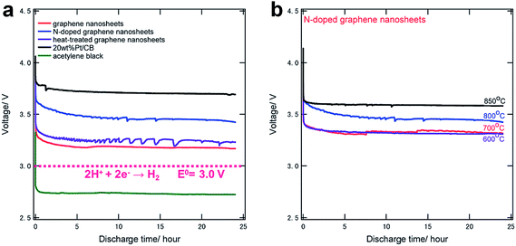 | ||
| Fig. 16 Discharge curves of (a) various carbons and (b) N-doped graphene samples annealed at various temperatures, both at a current density of 0.5 mA cm−2 for 24 hours.117 Reproduced from ref. 117 with permission from The Royal Society of Chemistry. | ||
4 Conclusion and outlook
Recent progress in Li/S and Li/air cells was reviewed with a focus on electrodes utilizing the properties of graphene. In the Li/S system, nanostructured graphene could aid in addressing the intrinsic challenges of poor kinetics, large volume expansion, and dissolution of polysulfides in the electrolyte, resulting in significant improvements in the cyclability and rate capability. In graphene/sulfur composites, graphene could effectively trap soluble polysulfides to minimize the shuttle effect. Fast charge transport, as well as buffering of the large volume expansion of the sulfur cathode, were possible,26,36,37 which promises these types of electrode design towards a viable Li/S cell. Nevertheless, there are numerous challenges that must be overcome. The sulfur content in the nanostructured cathode needs to be increased, and the tap density, which is essential to achieve the high volumetric energy density, must also be controlled, since the relatively low density of sulfur and graphene can affect adversely the volumetric energy density.21 While conventional electrode materials need less than 20% carbon by weight, the carbon content in the sulfur cathode is typically 40–60% by weight. Moreover, there remain issues on the reaction mechanism. Although several studies have investigated the electrochemical reaction through ex situ and in situ analyses,17,43,118 the reaction mechanism is still not completely understood. Because the characterization of sulfur cathodes is much more complicated than other conventional battery materials, more detailed and intensive study should be conducted for further development of Li/S batteries.In Li/air cells, graphene has shown diverse applications as a constituent material for air-electrodes, a catalyst or a substrate for other catalysts. The high conducting surface area of graphene enlarged the discharge capacity. It also increased the cycle efficiency by reducing the overpotential when used as a catalyst or hybrid catalyst. Moreover, graphene was an effective substrate for hybrid catalysts, where catalysts could be uniformly grown and good adhesion between graphene and catalyst particles was possible. The catalytic activity of catalyst particles could be enhanced by lowering the overpotential. However, it should be noted that while studies have shown improvements with graphene, most works have used carbonate-based electrolytes in their experiment. It implies that the role of graphene in Li/air cells need to be clarified further. Accordingly, further research on graphene should be investigated using stable electrolyte systems.
Acknowledgements
This work was supported by (i) Human Resources Development program (20124010203320) of the Korea Institute of Energy Technology Evaluation and Planning (KETEP) grant funded by the Korea Government Ministry of Trade, Industry and Energy, (ii) the National Research Foundation of Korea Grant funded by the Korean Government (MEST) (NRF-2009-0094219), and (iii) the Converging Research Center Program through the Ministry of Education, Science and Technology (2012K001267).References
- M. Armand and J. M. Tarascon, Nature, 2008, 451, 652–657 CrossRef CAS PubMed.
- A. S. Arico, P. Bruce, B. Scrosati, J.-M. Tarascon and W. van Schalkwijk, Nat. Mater., 2005, 4, 366–377 CrossRef CAS PubMed.
- X. Ji, K. T. Lee and L. F. Nazar, Nat. Mater., 2009, 8, 500–506 CrossRef CAS PubMed.
- B. Scrosati and J. Garche, J. Power Sources, 2010, 195, 2419–2430 CrossRef CAS PubMed.
- Y. Yang, M. T. McDowell, A. Jackson, J. J. Cha, S. S. Hong and Y. Cui, Nano Lett., 2010, 10, 1486–1491 CrossRef CAS PubMed.
- Y.-U. Park, D.-H. Seo, B. Kim, K.-P. Hong, H. Kim, S. Lee, R. A. Shakoor, K. Miyasaka, J.-M. Tarascon and K. Kang, Sci. Rep., 2012, 2, 704 Search PubMed.
- H. Kim, H.-D. Lim, S.-W. Kim, J. Hong, D.-H. Seo, D.-c. Kim, S. Jeon, S. Park and K. Kang, Sci. Rep., 2013, 3, 1506 CAS.
- S.-E. Cheon, K.-S. Ko, J.-H. Cho, S.-W. Kim, E.-Y. Chin and H.-T. Kim, J. Electrochem. Soc., 2003, 150, A800–A805 CrossRef CAS PubMed.
- W. Zheng, Y. W. Liu, X. G. Hu and C. F. Zhang, Electrochim. Acta, 2006, 51, 1330–1335 CrossRef CAS PubMed.
- J. Guo, Y. Xu and C. Wang, Nano Lett., 2011, 11, 4288–4294 CrossRef CAS PubMed.
- N. Jayaprakash, J. Shen, S. S. Moganty, A. Corona and L. A. Archer, Angew. Chem., 2011, 123, 6026–6030 CrossRef.
- P. G. Bruce, L. J. Hardwick and K. M. Abraham, MRS Bull., 2011, 36, 506–512 CrossRef CAS.
- B. Sun, B. Wang, D. Su, L. Xiao, H. Ahn and G. Wang, Carbon, 2012, 50, 727–733 CrossRef CAS PubMed.
- Y. Shao, S. Park, J. Xiao, J.-G. Zhang, Y. Wang and J. Liu, ACS Catal., 2012, 2, 844–857 CrossRef CAS.
- T. Zhang and H. Zhou, Angew. Chem., Int. Ed., 2012, 51, 11062–11067 CrossRef CAS PubMed.
- F. Cheng and J. Chen, Nat. Chem., 2012, 4, 962–963 CrossRef CAS PubMed.
- J. Nelson, S. Misra, Y. Yang, A. Jackson, Y. Liu, H. Wang, H. Dai, J. C. Andrews, Y. Cui and M. F. Toney, J. Am. Chem. Soc., 2012, 134, 6337–6343 CrossRef CAS PubMed.
- H.-S. Ryu, H.-J. Ahn, K.-W. Kim, J.-H. Ahn and J.-Y. Lee, J. Power Sources, 2006, 153, 360–364 CrossRef CAS PubMed.
- S. A. Freunberger, Y. Chen, Z. Peng, J. M. Griffin, L. J. Hardwick, F. Bardé, P. Novák and P. G. Bruce, J. Am. Chem. Soc., 2011, 133, 8040–8047 CrossRef CAS PubMed.
- P. G. Bruce, S. A. Freunberger, L. J. Hardwick and J.-M. Tarascon, Nat. Mater., 2012, 11, 19–29 CrossRef CAS PubMed.
- Y. Yang, G. Zheng and Y. Cui, Chem. Soc. Rev., 2013, 42, 3018–3032 RSC.
- F. Cheng and J. Chen, Chem. Soc. Rev., 2012, 41, 2172–2192 RSC.
- J. Christensen, P. Albertus, R. S. Sanchez-Carrera, T. Lohmann, B. Kozinsky, R. Liedtke, J. Ahmed and A. Kojic, J. Electrochem. Soc., 2012, 159, R1–R30 CrossRef CAS PubMed.
- G. Girishkumar, B. McCloskey, A. C. Luntz, S. Swanson and W. Wilcke, J. Phys. Chem. Lett., 2010, 1, 2193–2203 CrossRef CAS.
- M. J. Allen, V. C. Tung and R. B. Kaner, Chem. Rev., 2009, 110, 132–145 CrossRef PubMed.
- M. Choucair, P. Thordarson and J. A. Stride, Nat. Nanotechnol., 2009, 4, 30–33 CrossRef CAS PubMed.
- R. Hawaldar, P. Merino, M. R. Correia, I. Bdikin, J. Grácio, J. Méndez, J. A. Martín-Gago and M. K. Singh, Sci. Rep., 2012, 2, 682 CrossRef PubMed.
- X. Geng, Y. Guo, D. Li, W. Li, C. Zhu, X. Wei, M. Chen, S. Gao, S. Qiu, Y. Gong, L. Wu, M. Long, M. Sun, G. Pan and L. Liu, Sci. Rep., 2013, 3, 1134 CAS.
- M. A. Worsley, P. J. Pauzauskie, T. Y. Olson, J. Biener, J. H. Satcher and T. F. Baumann, J. Am. Chem. Soc., 2010, 132, 14067–14069 CrossRef CAS PubMed.
- X. Li, G. Zhang, X. Bai, X. Sun, X. Wang, E. Wang and H. Dai, Nat. Nanotechnol., 2008, 3, 538–542 CrossRef CAS PubMed.
- Z.-S. Wu, W. Ren, L. Gao, B. Liu, C. Jiang and H.-M. Cheng, Carbon, 2009, 47, 493–499 CrossRef CAS PubMed.
- E. Yoo and H. Zhou, ACS Nano, 2011, 5, 3020–3026 CrossRef CAS PubMed.
- S. Wang, S. Dong, J. Wang, L. Zhang, P. Han, C. Zhang, X. Wang, K. Zhang, Z. Lan and G. Cui, J. Mater. Chem., 2012, 22, 21051–21056 RSC.
- Y. Cao, Z. Wei, J. He, J. Zang, Q. Zhang, M. Zheng and Q. Dong, Energy Environ. Sci., 2012, 5, 9765–9768 CAS.
- L. Wang, X. Zhao, Y. Lu, M. Xu, D. Zhang, R. S. Ruoff, K. J. Stevenson and J. B. Goodenough, J. Electrochem. Soc., 2011, 158, A1379–A1382 CrossRef CAS PubMed.
- H. Wang, Y. Yang, Y. Liang, J. T. Robinson, Y. Li, A. Jackson, Y. Cui and H. Dai, Nano Lett., 2011, 11, 2644–2647 CrossRef CAS PubMed.
- L. Ji, M. Rao, H. Zheng, L. Zhang, Y. Li, W. Duan, J. Guo, E. J. Cairns and Y. Zhang, J. Am. Chem. Soc., 2011, 133, 18522–18525 CrossRef CAS PubMed.
- Y. Cao, X. Li, I. A. Aksay, J. Lemmon, Z. Nie, Z. Yang and J. Liu, Phys. Chem. Chem. Phys., 2011, 13, 7660–7665 RSC.
- S. Evers and L. F. Nazar, Chem. Commun., 2012, 48, 1233–1235 RSC.
- J. Xiao, D. Mei, X. Li, W. Xu, D. Wang, G. L. Graff, W. D. Bennett, Z. Nie, L. V. Saraf, I. A. Aksay, J. Liu and J.-G. Zhang, Nano Lett., 2011, 11, 5071–5078 CrossRef CAS PubMed.
- Y. Li, J. Wang, X. Li, D. Geng, R. Li and X. Sun, Chem. Commun., 2011, 47, 9438–9440 RSC.
- J. R. Akridge, Y. V. Mikhaylik and N. White, Solid State Ionics, 2004, 175, 243–245 CrossRef CAS PubMed.
- L. Yuan, X. Qiu, L. Chen and W. Zhu, J. Power Sources, 2009, 189, 127–132 CrossRef CAS PubMed.
- C. Barchasz, F. Molton, C. Duboc, J.-C. Leprêtre, S. Patoux and F. Alloin, Anal. Chem., 2012, 84, 3973–3980 CrossRef CAS PubMed.
- K. Cai, M.-K. Song, E. J. Cairns and Y. Zhang, Nano Lett., 2012, 12, 6474–6479 CrossRef CAS PubMed.
- G. Zheng, Y. Yang, J. J. Cha, S. S. Hong and Y. Cui, Nano Lett., 2011, 11, 4462–4467 CrossRef CAS PubMed.
- S.-R. Chen, Y.-P. Zhai, G.-L. Xu, Y.-X. Jiang, D.-Y. Zhao, J.-T. Li, L. Huang and S.-G. Sun, Electrochim. Acta, 2011, 56, 9549–9555 CrossRef CAS PubMed.
- J.-Z. Wang, L. Lu, M. Choucair, J. A. Stride, X. Xu and H.-K. Liu, J. Power Sources, 2011, 196, 7030–7034 CrossRef CAS PubMed.
- B. Wang, K. Li, D. Su, H. Ahn and G. Wang, Chem.–Asian J., 2012, 7, 1637–1643 CrossRef CAS PubMed.
- N. Li, M. Zheng, H. Lu, Z. Hu, C. Shen, X. Chang, G. Ji, J. Cao and Y. Shi, Chem. Commun., 2012, 48, 4106–4108 RSC.
- M. Xiao, M. Huang, S. Zeng, D. Han, S. Wang, L. Sun and Y. Meng, RSC Adv., 2013, 3, 4914–4916 RSC.
- M.-S. Park, J.-S. Yu, K. J. Kim, G. Jeong, J.-H. Kim, Y.-N. Jo, U. Hwang, S. Kang, T. Woo and Y.-J. Kim, Phys. Chem. Chem. Phys., 2012, 14, 6796–6804 RSC.
- H. Sun, G.-L. Xu, Y.-F. Xu, S.-G. Sun, X. Zhang, Y. Qiu and S. Yang, Nano Res., 2012, 5, 726–738 CrossRef CAS.
- Z.-k. Wei, J.-j. Chen, L.-l. Qin, A.-w. Nemage, M.-s. Zheng and Q.-f. Dong, J. Electrochem. Soc., 2012, 159, A1236–A1239 CrossRef CAS PubMed.
- F. Zhang, Y. Dong, Y. Huang, G. Huang, X. Zhang and L. Wang, J. Phys.: Conf. Ser., 2012, 339, 012003 CrossRef.
- X. Ji and L. F. Nazar, J. Mater. Chem., 2010, 20, 9821–9826 RSC.
- F.-f. Zhang, X.-b. Zhang, Y.-h. Dong and L.-m. Wang, J. Mater. Chem., 2012, 22, 11452–11454 RSC.
- B. Ding, C. Yuan, L. Shen, G. Xu, P. Nie, Q. Lai and X. Zhang, J. Mater. Chem. A, 2013, 1, 1096–1101 CAS.
- M. Rao, X. Song, H. Liao and E. J. Cairns, Electrochim. Acta, 2012, 65, 228–233 CrossRef CAS PubMed.
- J. Jin, Z. Wen, G. Ma, Y. Lu, Y. Cui, M. Wu, X. Liang and X. Wu, RSC Adv., 2013, 3, 2558–2560 RSC.
- R. Sharma, J. H. Baik, C. J. Perera and M. S. Strano, Nano Lett., 2010, 10, 398–405 CrossRef CAS PubMed.
- A. Eftekhari and B. Yazdani, J. Polym. Sci., Part A: Polym. Chem., 2010, 48, 2204–2213 CrossRef CAS.
- C. Uthaisar and V. Barone, Nano Lett., 2010, 10, 2838–2842 CrossRef CAS PubMed.
- H.-G. Jung, J. Hassoun, J.-B. Park, Y.-K. Sun and B. Scrosati, Nat. Chem., 2012, 4, 579–585 CrossRef CAS PubMed.
- Z. Peng, S. A. Freunberger, Y. Chen and P. G. Bruce, Science, 2012, 337, 563–566 CrossRef CAS PubMed.
- H.-D. Lim, K.-Y. Park, H. Song, E. Y. Jang, H. Gwon, J. Kim, Y. H. Kim, M. D. Lima, R. O. Robles, X. Lepró, R. H. Baughman and K. Kang, Adv. Mater., 2012, 25, 1348–1352 CrossRef PubMed.
- J. Hassoun, F. Croce, M. Armand and B. Scrosati, Angew. Chem., Int. Ed., 2011, 50, 2999–3002 CrossRef CAS PubMed.
- Z. Peng, S. A. Freunberger, L. J. Hardwick, Y. Chen, V. Giordani, F. Bardé, P. Novák, D. Graham, J.-M. Tarascon and P. G. Bruce, Angew. Chem., 2011, 123, 6475–6479 CrossRef.
- Y.-C. Lu, B. M. Gallant, D. G. Kwabi, J. R. Harding, R. R. Mitchell, M. S. Whittingham and Y. Shao-Horn, Energy Environ. Sci., 2013, 6, 750–768 CAS.
- S. H. Oh, R. Black, E. Pomerantseva, J.-H. Lee and L. F. Nazar, Nat. Chem., 2012, 4, 1004–1010 CrossRef CAS PubMed.
- K. M. Abraham and Z. Jiang, J. Electrochem. Soc., 1996, 143, 1–5 CrossRef CAS PubMed.
- H.-D. Lim, H. Gwon, H. Kim, S.-W. Kim, T. Yoon, J. W. Choi, S. M. Oh and K. Kang, Electrochim. Acta, 2013, 90, 63–70 CrossRef CAS PubMed.
- B. D. McCloskey, D. S. Bethune, R. M. Shelby, G. Girishkumar and A. C. Luntz, J. Phys. Chem. Lett., 2011, 2, 1161–1166 CrossRef CAS.
- C. O. Laoire, S. Mukerjee, E. J. Plichta, M. A. Hendrickson and K. M. Abraham, J. Electrochem. Soc., 2011, 158, A302–A308 CrossRef CAS PubMed.
- H.-D. Lim, K.-Y. Park, H. Gwon, J. Hong, H. Kim and K. Kang, Chem. Commun., 2012, 48, 8374–8376 RSC.
- C. O. Laoire, S. Mukerjee, K. M. Abraham, E. J. Plichta and M. A. Hendrickson, J. Phys. Chem. C, 2010, 114, 9178–9186 CAS.
- D. Xu, Z.-l. Wang, J.-j. Xu, L.-l. Zhang, L.-m. Wang and X.-b. Zhang, Chem. Commun., 2012, 48, 11674–11676 RSC.
- D. Xu, Z.-l. Wang, J.-j. Xu, L.-l. Zhang and X.-b. Zhang, Chem. Commun., 2012, 48, 6948–6950 RSC.
- S. A. Freunberger, Y. Chen, N. E. Drewett, L. J. Hardwick, F. Bardé and P. G. Bruce, Angew. Chem., Int. Ed., 2011, 50, 8609–8613 CrossRef CAS PubMed.
- E. Nasybulin, W. Xu, M. H. Engelhard, Z. Nie, S. D. Burton, L. Cosimbescu, M. E. Gross and J.-G. Zhang, J. Phys. Chem. C, 2013, 117, 2635–2645 CAS.
- W. Walker, V. Giordani, J. Uddin, V. S. Bryantsev, G. V. Chase and D. Addison, J. Am. Chem. Soc., 2013, 135, 2076–2079 CrossRef CAS PubMed.
- B. G. Kim, J.-N. Lee, D. J. Lee, J.-K. Park and J. W. Choi, ChemSusChem, 2013, 6, 443–448 CrossRef CAS PubMed.
- M. M. O. Thotiyl, S. A. Freunberger, Z. Peng and P. G. Bruce, J. Am. Chem. Soc., 2012, 135, 494–500 CrossRef PubMed.
- B. D. McCloskey, A. Speidel, R. Scheffler, D. C. Miller, V. Viswanathan, J. S. Hummelshøj, J. K. Nørskov and A. C. Luntz, J. Phys. Chem. Lett., 2012, 3, 997–1001 CrossRef CAS.
- J. Xiao, D. Wang, W. Xu, D. Wang, R. E. Williford, J. Liu and J.-G. Zhang, J. Electrochem. Soc., 2010, 157, A487–A492 CrossRef CAS PubMed.
- J.-J. Xu, D. Xu, Z.-L. Wang, H.-G. Wang, L.-L. Zhang and X.-B. Zhang, Angew. Chem., Int. Ed., 2013, 52, 3887–3890 CrossRef CAS PubMed.
- M. Mirzaeian and P. J. Hall, Electrochim. Acta, 2009, 54, 7444–7451 CrossRef CAS PubMed.
- J. Read, J. Electrochem. Soc., 2002, 149, A1190–A1195 CrossRef CAS PubMed.
- Z.-L. Wang, D. Xu, J.-J. Xu, L.-L. Zhang and X.-B. Zhang, Adv. Funct. Mater., 2012, 22, 3699–3705 CrossRef CAS.
- S. D. Beattie, D. M. Manolescu and S. L. Blair, J. Electrochem. Soc., 2009, 156, A44–A47 CrossRef CAS PubMed.
- S. S. Zhang, X. Ren and J. Read, Electrochim. Acta, 2011, 56, 4544–4548 CrossRef CAS PubMed.
- D. Zheng, H.-S. Lee, X.-Q. Yang and D. Qu, Electrochem. Commun., 2013, 28, 17–19 CrossRef CAS PubMed.
- S. R. Gowda, A. Brunet, G. M. Wallraff and B. D. McCloskey, J. Phys. Chem. Lett., 2012, 4, 276–279 CrossRef.
- Y.-C. Lu and Y. Shao-Horn, J. Phys. Chem. Lett., 2012, 4, 93–99 CrossRef.
- S. S. Zhang, K. Xu and J. Read, J. Power Sources, 2011, 196, 3906–3910 CrossRef CAS PubMed.
- S. S. Zhang, D. Foster and J. Read, J. Power Sources, 2010, 195, 1235–1240 CrossRef CAS PubMed.
- S. Stankovich, D. A. Dikin, R. D. Piner, K. A. Kohlhaas, A. Kleinhammes, Y. Jia, Y. Wu, S. T. Nguyen and R. S. Ruoff, Carbon, 2007, 45, 1558–1565 CrossRef CAS PubMed.
- J.-S. Lee, S. T. Kim, R. Cao, N.-S. Choi, M. Liu, K. T. Lee and J. Cho, Adv. Energy Mater., 2011, 1, 34–50 CrossRef CAS.
- C. Tran, X.-Q. Yang and D. Qu, J. Power Sources, 2010, 195, 2057–2063 CrossRef CAS PubMed.
- D. Deng, L. Yu, X. Pan, S. Wang, X. Chen, P. Hu, L. Sun and X. Bao, Chem. Commun., 2011, 47, 10016–10018 RSC.
- H. Kim, K. Lee, S. I. Woo and Y. Jung, Phys. Chem. Chem. Phys., 2011, 13, 17505–17510 RSC.
- K. R. Lee, K. U. Lee, J. W. Lee, B. T. Ahn and S. I. Woo, Electrochem. Commun., 2010, 12, 1052–1055 CrossRef CAS PubMed.
- Z.-S. Wu, W. Ren, L. Wen, L. Gao, J. Zhao, Z. Chen, G. Zhou, F. Li and H.-M. Cheng, ACS Nano, 2010, 4, 3187–3194 CrossRef CAS PubMed.
- H. Kim, D.-H. Seo, S.-W. Kim, J. Kim and K. Kang, Carbon, 2011, 49, 326–332 CrossRef CAS PubMed.
- S.-M. Paek, E. Yoo and I. Honma, Nano Lett., 2008, 9, 72–75 CrossRef PubMed.
- S. Ding, D. Luan, F. Y. C. Boey, J. S. Chen and X. W. Lou, Chem. Commun., 2011, 47, 7155–7157 RSC.
- B. Wang, J. Park, C. Wang, H. Ahn and G. Wang, Electrochim. Acta, 2010, 55, 6812–6817 CrossRef CAS PubMed.
- Y. Liang, Y. Li, H. Wang, J. Zhou, J. Wang, T. Regier and H. Dai, Nat. Mater., 2011, 70, 780–786 CrossRef PubMed.
- H. Wang, Y. Yang, Y. Liang, G. Zheng, Y. Li, Y. Cui and H. Dai, Energy Environ. Sci., 2012, 5, 7931–7935 CAS.
- J. Campos-Delgado, J. M. Romo-Herrera, X. Jia, D. A. Cullen, H. Muramatsu, Y. A. Kim, T. Hayashi, Z. Ren, D. J. Smith, Y. Okuno, T. Ohba, H. Kanoh, K. Kaneko, M. Endo, H. Terrones, M. S. Dresselhaus and M. Terrones, Nano Lett., 2008, 8, 2773–2778 CrossRef CAS PubMed.
- W. S. Hummers and R. E. Offeman, J. Am. Chem. Soc., 1958, 80, 1339–1339 CrossRef CAS.
- C. Zhu, S. Guo, Y. Fang and S. Dong, ACS Nano, 2010, 4, 2429–2437 CrossRef CAS PubMed.
- D. Higgins, Z. Chen, D. U. Lee and Z. Chen, J. Mater. Chem. A, 2013, 1, 2639–2645 CAS.
- Y. Shao, S. Zhang, M. H. Engelhard, G. Li, G. Shao, Y. Wang, J. Liu, I. A. Aksay and Y. Lin, J. Mater. Chem., 2010, 20, 7491–7496 RSC.
- H. Wang, T. Maiyalagan and X. Wang, ACS Catal., 2012, 2, 781–794 CrossRef CAS.
- D. Geng, Y. Chen, Y. Chen, Y. Li, R. Li, X. Sun, S. Ye and S. Knights, Energy Environ. Sci., 2011, 4, 760–764 CAS.
- E. Yoo, J. Nakamura and H. Zhou, Energy Environ. Sci., 2012, 5, 6928–6932 CAS.
- S.-E. Cheon, K.-S. Ko, J.-H. Cho, S.-W. Kim, E.-Y. Chin and H.-T. Kim, J. Electrochem. Soc., 2003, 150, A796–A799 CrossRef CAS PubMed.
Footnote |
| † These authors contributed equally to this work. |
| This journal is © The Royal Society of Chemistry 2014 |


