 Open Access Article
Creative Commons Attribution 3.0 Unported Licence
Universal enantioselective discrimination by Raman spectroscopy
Johannes
Kiefer
*acd and
Kristina
Noack
bd
aTechnische Thermodynamik, Universität Bremen, Badgasteiner Str. 1, 28359 Bremen, Germany. E-mail: jkiefer@uni-bremen.de
bLehrstuhl für Technische Thermodynamik, Universität Erlangen-Nürnberg, Am Weichselgarten 8, 91058 Erlangen, Germany
cSchool of Engineering, University of Aberdeen, Fraser Noble Building, Aberdeen AB24 3UE, UK
dErlangen Graduate School in Advanced Optical Technologies, Universität Erlangen-Nürnberg, 91052 Erlangen, Germany
First published on 28th January 2015
Abstract
Distinguishing between the enantiomers of chiral substances and their quantification is an analytical challenge, in particular in the pharmaceutical and biochemical sectors. A Raman spectroscopic method for discrimination of enantiomers is proposed. Advantage is taken of the polarization properties when Raman scattering occurs in an optically active medium. It is shown that a conventional polarization-resolved Raman setup leads to identical spectra of the two enantiomers. However, inserting a half-wave retarder to rotate the signal polarization by a fixed angle enables the efficient and universal enantiomeric discrimination. Hence, the applicability of any polarization-resolved Raman experiment can be improved substantially without significant modification of the setup or the use of chiral labeling or the addition of a substrate for selective plasmonic enhancement. In principle, the proposed technique allows simultaneous speciation, enantiomeric discrimination, as well as structural and quantitative analysis.
Chiral molecules are of great relevance, in particular in the areas of biology and pharmaceutical science.1 The enantiomers of a chiral substance may exhibit very different physiological effects. The most prominent and tragic example is thalidomide, a drug which caused birth defects in thousands of children in the 1950s and 60s.2 Therefore, it is important that chiral molecules are produced with high enantiomeric purity. In order to characterize a substance and monitor it during the synthesis and purification process, suitable analytical methods are required. In particular, the enantiomeric discrimination is difficult, as the enantiomers possess identical physicochemical properties. Furthermore, chemical synthesis usually generates the racemate, which is a 1
![[thin space (1/6-em)]](https://www.rsc.org/images/entities/char_2009.gif) :
:![[thin space (1/6-em)]](https://www.rsc.org/images/entities/char_2009.gif) 1 mixture of both enantiomers.
1 mixture of both enantiomers.
The list of existing analytical techniques to differentiate enantiomers includes capillary electrophoresis (CE),3 NMR,4 microwave5 and fluorescence6 spectroscopy, vibrational circular dichroism (VCD),7 and Raman optical activity (ROA).8 Very recently, cavity ringdown polarimetry9 and surface enhanced Raman spectroscopy (SERS)10 have been demonstrated as tools for enantiomeric discrimination as well. However, all these methods have significant disadvantages. Some of them are time-consuming and hence do not provide sufficient time-resolution for process monitoring, some require molecular labeling or the addition of a chemical agent, and some are expensive and experimentally complicated.
Conventional Raman spectroscopy has not been considered as a method for enantiomeric discrimination. Quite the contrary, it is a widely held belief that the technique is generally not suitable for this purpose. It was even stated explicitly that Raman spectroscopy cannot differentiate between enantiomers, see e.g.ref. 10. In the following, we will demonstrate that Raman spectroscopy can be made a truly universal tool for enantiomeric discrimination, when the signal is recorded polarization-resolved and a simple have-wave retarder is inserted in the setup. The approach described and the data presented are based on a previous paper,11 in which a theoretical framework of the polarization phenomena with respect to the laser and Raman signal propagation in optically active samples was described.
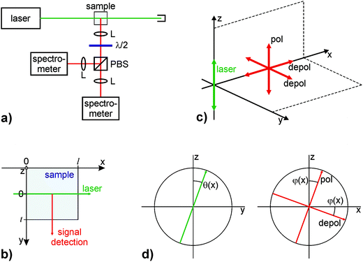
Fig. 1a shows the sketch of a Raman setup with polarization-resolved signal detection. A linearly polarized laser beam passes the sample, e.g. a liquid in a glass cuvette, and is then blocked by a beam dump. In direction perpendicular to the laser beam, the scattered light is collected and collimated by an achromatic lens. A polarizing beam splitter separates the vertically and horizontally polarized fractions of the signal before they are spectrally dispersed and recorded in spectrometers. The geometric details of importance are illustrated in panel (b) of Fig. 1. The x-axis denotes the beam direction and the y-axis corresponds to the direction in which the signal is detected. The z-axis is orthogonal to both and represents the initial polarization direction of the laser. In this configuration and under the assumption that the sample is not optically active, there will be the polarized Raman signal oscillating in z-direction and two depolarized components in x- and y-direction as displayed in panel (c). When the sample is optically active, however, we need to take into account that the laser polarization is rotated when travelling through the sample, and the signal is rotated as well (cf. Fig. 1d). In other words, the polarization-resolved Raman signal changes with the location, x, where it is generated. A detailed theoretical framework of the effects is given and discussed in reference.11 To simplify matter, we consider an infinitesimally small laser beam, and a signal collection with infinitesimally small solid angle. In this case, the detected vertically and horizontally polarized intensities can be written as
 | (1) |
 | (2) |
The data presented in the following were simulated using eqn (1) and (2) fed with experimentally determined parameters. This approach allows looking at the physical effects without possible interference from experimental artifacts. As a model system, solutions of 0.18 g cm−3 α-D- or α-L-glucose in dimethyl sulfoxide (DMSO) were considered in an l = 1 cm glass cuvette. The specific rotation determined with a linearly polarized HeNe laser was ±2° cm−1. As aforesaid, for the simulation the beam is considered infinitesimally thin and only the Raman signal generated in the center of the cuvette is taken into account (x = 0.5 cm and θ = ±1°). The signal travels t = 1 cm inside the solution before it exits the cuvette. Only the CSC symmetric and antisymmetric stretching modes of DMSO are considered. They manifest in Gaussian peaks at 669 and 697 cm−1, each exhibiting a spectral width of 10 cm−1 full width at half maximum (FWHM). This double peak is selected, as it is free of interference from glucose signals.11 In addition, both peaks exhibit substantially different depolarization ratios (0.06 and 0.31, respectively), which helps to illustrate the effects.
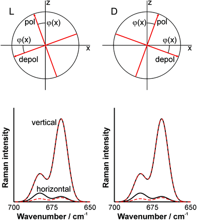
Let us now consider the two cases that the sample contains either one or the other enantiomer of α-glucose and let us evaluate the effects on the Raman signal components detected with vertical and horizontal polarization. The D-enantiomere exhibits a positive specific rotation and the L-form a negative one, both identical regarding the absolute value. Consequently, employing a conventional polarization-resolved Raman setup, the signals generated in both solutions will exhibit the same angle of rotation but with different sign (see upper panels of Fig. 2). Hence, the signals recorded will be identical as illustrated by the CSC stretching vibrations of DMSO displayed in the lower panels of Fig. 2 (dashed lines). The signal in pure DMSO, i.e. without any optical activity, is shown as solid line for comparison. Obviously, enantiomeric discrimination is not possible in this case.
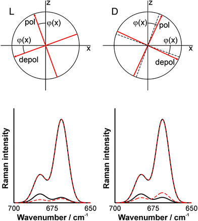
In order to overcome this problem, we can utilize the phase relationships of the signal components. If the signal polarization of the enantiomer solutions can be rotated in such a way that they exhibit different angles (regarding their absolute value) before the beam splitter, enantiomeric discrimination would be possible. This can be achieved by inserting a retarder with a phase-shift of π, e.g. an achromatic half-wave plate (or a double Fresnel rhomb), as indicated in Fig. 1a. Unless the fast or slow axes of the wave plate coincides with the x- or y-axis, the polarization of the polarized and depolarized signal components will be rotated differently for both enantiomers. Fig. 3 illustrates the situation when the fast axis of the wave plate coincides with the polarization direction of the L-enantiomere. In this case, the signals from the L-glucose solution are not altered, while the signal polarization of the D-glucose solution is further rotated as shown in the right upper panel of Fig. 3. Consequently, the polarization-resolved signals will be different for both enantiomers as illustrated in the lower panels (note that the analog effect can be observed, when the fast axis of the wave plate coincides with the polarization direction of the D-enantiomere). In particular, the horizontally polarized component reveals significant differences. Thus, enantiomeric discrimination is now possible.
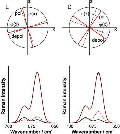
When the wave plate is slightly rotated so that none of the signal components coincides with the fast axis, the situation illustrated in Fig. 4 manifests. The signals from both solutions are rotated, but the angles are different. Hence, again, the polarization-resolved signals show distinct differences. As a rule of thumb, we can note that the higher the asymmetry of the polarization diagrams shown in the upper panels, the more pronounced the differences in the spectra and the clearer the enantiomeric discrimination.
In conclusion, a Raman spectroscopy method for universal enantiomeric discrimination was proposed. Inserting a half-wave retarder in the collimated signal rotates the polarized and depolarized signal components differently for the individual enantiomers and thus allows spectroscopic discrimination. This simple extension makes conventional Raman spectroscopy a unique analytical tool for chiral molecules. Traditionally, the Raman spectrum provides access to the chemical structure and interactions with the molecular environment,12 and allows quantitative compositional analysis.13 With the proposed extension, enantiomeric discrimination and the determination of the enantiomeric ratio is possible. It is important to note that this discrimination does not require anything specific to the substances under investigation and hence is a truly universal tool. It should also be pointed out that the proposed technique is substantially different from Raman optical activity. The latter makes use of a vibrational optical activity, which is a very weak effect. Therefore, ROA measurements often take extended periods of time (up to days and longer). In contrast, our method can provide high temporal resolution (fractions of a second) when appropriate equipment is used. Consequently, polarization-resolved Raman spectroscopy is perfectly suited for monitoring the production of chiral substances and characterizing their behavior in practical applications.
The authors gratefully acknowledge funding of the Erlangen Graduate School in Advanced Optical Technologies (SAOT) by the German Research Foundation (DFG) in the framework of the German excellence initiative.
References
- R. E. Morris and X. H. Bu, Nat. Chem., 2010, 2, 353–361 CrossRef CAS PubMed.
- M. Emanuel, M. Rawlins, G. Duff and A. Breckenridge, Lancet, 2012, 380, 781–783 CrossRef.
- A. Amini, Electrophoresis, 2001, 22, 3107–3130 CrossRef CAS.
- D. Parker, Chem. Rev., 1991, 91, 1441–1457 CrossRef CAS.
- D. Patterson, M. Schnell and J. M. Doyle, Nature, 2013, 497, 475 CrossRef CAS PubMed.
- T. D. James, K. Sandanayake and S. Shinkai, Nature, 1995, 374, 345–347 CrossRef CAS.
- P. J. Stephens, F. J. Devlin and J. J. Pan, Chirality, 2008, 20, 643–663 CrossRef CAS PubMed.
- L. D. Barron, L. Hecht, E. W. Blanch and A. F. Bell, Prog. Biophys. Mol. Biol., 2000, 73, 1–49 CrossRef CAS.
- D. Sofikitis, L. Bougas, G. E. Katsoprinakis, A. K. Spiliotis, B. Loppinet and T. P. Rakitzis, Nature, 2014, 514, 76–79 CrossRef CAS PubMed.
- Y. Wang, Z. Yu, W. Ji, Y. Tanaka, H. Sui, B. Zhao and Y. Ozaki, Angew. Chem., Int. Ed., 2014, 53, 13866–13870 CrossRef CAS PubMed.
- J. Kiefer and M. Kaspereit, Anal. Methods, 2013, 5, 797–800 RSC.
- R. W. Berg, Appl. Spectr. Rev., 2015, 50, 193–239 CrossRef CAS.
- K. Noack, B. Eskofier, J. Kiefer, C. Dilk, G. Bilow, M. Schirmer, R. Buchholz and A. Leipertz, Analyst, 2013, 138, 5639–5646 RSC.
| This journal is © The Royal Society of Chemistry 2015 |


