 Open Access Article
The grid-based fast multipole method – a massively parallel numerical scheme for calculating two-electron interaction energies
Elias A.
Toivanen
,
Sergio A.
Losilla†
and
Dage
Sundholm
*
Department of Chemistry, University of Helsinki, A. I. Virtanens plats 1, P. O. Box 55, FI-00014, Finland. E-mail: eatoivan@chem.helsinki.fi; Dage.Sundholm@helsinki.fi
First published on 11th May 2015
Abstract
Algorithms and working expressions for a grid-based fast multipole method (GB-FMM) have been developed and implemented. The computational domain is divided into cubic subdomains, organized in a hierarchical tree. The contribution to the electrostatic interaction energies from pairs of neighboring subdomains is computed using numerical integration, whereas the contributions from further apart subdomains are obtained using multipole expansions. The multipole moments of the subdomains are obtained by numerical integration. Linear scaling is achieved by translating and summing the multipoles according to the tree structure, such that each subdomain interacts with a number of subdomains that are almost independent of the size of the system. To compute electrostatic interaction energies of neighboring subdomains, we employ an algorithm which performs efficiently on general purpose graphics processing units (GPGPU). Calculations using one CPU for the FMM part and 20 GPGPUs consisting of tens of thousands of execution threads for the numerical integration algorithm show the scalability and parallel performance of the scheme. For calculations on systems consisting of Gaussian functions (α = 1) distributed as fullerenes from C20 to C720, the total computation time and relative accuracy (ppb) are independent of the system size.
1 Introduction
Computational speed has doubled every 18 months since the birth of the first computer. The exponential growth of the computational efficiency is called Moore's law.1 However, the computational speed of the individual processors has already practically reached its maximum using silicon-based technology, and the primary means to improve the performance is parallelization.The parallelization of quantum chemistry codes is not a trivial task, especially when aiming at implementations that run efficiently on thousands of central processing units (CPU) or general purpose graphics processing units (GPGPU), although great advances have been made in recent years.2–15 For example, Yasuda and Maruoka16 report a speed-up of four when using a GPGPU-accelerated version of their electron repulsion integral code, which is to be contrasted with the theoretical peak performance advertised by GPGPU vendors that suggest several orders of magnitude better results.
Setting technicalities such as memory access patterns and communication overheads aside, the software–hardware gap ultimately results from a mismatch between computer algorithms and the execution model of the computer hardware. In particular, maximal performance can never be attained if the focus is on the parallelization of individual code segments interleaved by sequential parts, which is the core content of Amdahl's law.17 It states that for massively parallel computers, the wall time it takes to perform given calculations is determined by the computational time that is needed to perform the operations in the serial part of the code. The law seems to introduce severe limitations, because if 10% of the code is run serially the maximum speed-up is a factor of about 10. However, if the time needed for the serial part can be made more or less independent of the amount of parameters needed to describe the molecule, the total computational scaling becomes independent of the size of the molecule, as long as a sufficiently large computer is available. Alternatively, if the size of the system is kept the same, a higher accuracy is obtained at the same cost.
To be able to explore the computational capacity of future computers one has to design algorithms that run efficiently on massively parallel computers. Real-space grid-based methods, also known as numerical methods are well-suited for these architectures because the local support of the basis functions introduces new opportunities to divide the calculation into lots of independent parts that can be performed in parallel. Once numerical integration can be performed concurrently on sufficiently many cores, the performance is not going to be limited by the total amount of work but by the work per computational node. In addition, the flexibility of numerical approaches also renders accurate calculations with small basis-set truncation errors (μEh) feasible.18–24 Thus, quantum chemistry calculations of the future employ local basis functions.
In this work, we discuss a fully numerical technique for computing electrostatic interaction energies between charge densities. In the context of ab initio electronic structure calculations, this is needed to compute large numbers of two-electron repulsion integrals. The evaluation of these integrals constitutes one of the computational bottlenecks of the self-consistent-field (SCF) calculations. Implementation of the FMM scheme in quantum chemistry codes that rely on atom-centered Gaussian-type basis sets significantly reduces the number of explicit integrals over the basis functions.25–29 Instead of the ![[scr O, script letter O]](https://www.rsc.org/images/entities/char_e52e.gif) (M4) integrals in the naive case, the FMM-accelerated prescreening scheme computes all interactions with only
(M4) integrals in the naive case, the FMM-accelerated prescreening scheme computes all interactions with only ![[scr O, script letter O]](https://www.rsc.org/images/entities/char_e52e.gif) (M) work, as demonstrated by e.g. Rudberg and Sałek.29 We have adapted the FMM scheme originally conceived by Greengard and Rokhlin30 and introduced it into quantum chemistry codes provided by White and Head-Gordon et al.31,32 to a fully numerical framework. In the grid-based fast multipole method (GB-FMM), the long-ranged and short-ranged contributions of the two-electron interactions are identified and treated differently. The long-ranged interactions are computed using an FMM scheme with numerically calculated multipole moments, whereas the short-ranged contributions are obtained by numerical integration as described in our previous work.15,33–36 For a discussion of alternative parallelization techniques for Poisson solvers, we refer to the recent survey by García-Risueño et al.37
(M) work, as demonstrated by e.g. Rudberg and Sałek.29 We have adapted the FMM scheme originally conceived by Greengard and Rokhlin30 and introduced it into quantum chemistry codes provided by White and Head-Gordon et al.31,32 to a fully numerical framework. In the grid-based fast multipole method (GB-FMM), the long-ranged and short-ranged contributions of the two-electron interactions are identified and treated differently. The long-ranged interactions are computed using an FMM scheme with numerically calculated multipole moments, whereas the short-ranged contributions are obtained by numerical integration as described in our previous work.15,33–36 For a discussion of alternative parallelization techniques for Poisson solvers, we refer to the recent survey by García-Risueño et al.37
Even though the FMM scheme is surely a key component in the quest for linear scaling SCF calculations,38 our interest in the FMM algorithm does not stem merely from asymptotic complexity arguments. Instead, we also tackle a somewhat different problem that is typical for grid-based methods, namely that the memory requirements for representing functions on a grid grow linearly with the volume of the system. The FMM scheme allows one to circumvent such limitations as it provides a natural framework for decomposing functions into local grids that can be distributed across several computational nodes opening the avenue for massive parallelization.
The article is outlined as follows. In Section 2, the GB-FMM scheme is thoroughly described. The bipolar series expansion of electrostatic interactions and the translation of multipole moments are discussed in Sections 2.1 and 2.2. The partitioning of the computational domain and the grids are described in Sections 2.3 and 2.4. The expressions for the calculation of the two-electron interaction energy using numerical integration combined with the GB-FMM scheme are derived in Section 2.5. The algorithm for calculating multipole moments is presented in Section 2.7, whereas the algorithm of the direct numerical integration of the near-field contributions to the two-electron interaction is described in Section 2.8. The different components are put together in Section 2.9, where the final algorithm is given. The timings and accuracy of the calculations are presented in Section 3. The article ends with conclusions and a future outlook in Section 4.
2 The grid-based fast multipole method
The ultimate goal is efficient calculations of the Nρ(Nρ + 1)/2 distinct pair interactions resulting from Nρ charge distributions, that is | (1) |
In this section, we present different expressions and methods required to arrive to the final expression for the energy, eqn (26). The algorithm to efficiently evaluate the interaction energy is then given in Section 2.9.
2.1 Bipolar expansion of electrostatic interactions
The mathematical basis of the fast multipole method is the bipolar series expansion39 of the Coulomb potential: | (2) |
Eqn (2) conveniently decouples coordinates r and r′, which significantly simplifies the evaluation of the interaction energy in eqn (1). The pair interaction energy can now be written as
 | (3) |
 | (4) |
Organizing the multipole moments as vector qμ, eqn (3) can be rewritten as
| Uμν = qTμ(P)vν(P). | (5) |
| vν(P) = T(Q − P)qν(Q). | (6) |
The elements of the potential vectors vν(P) have a direct physical significance,31 as they are the expansion coefficients in solid harmonics of the electric potential due to ρν(r) expanded around P:
 | (7) |
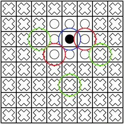 | ||
| Fig. 1 The blue sphere overlaps with the red spheres, but not with the green spheres. Hence, the interaction of the density enclosed in the box marked with a black circle with the boxes marked with white circles must be computed directly using eqn (1). On the other hand, the interaction between the box with the black circle and the boxes with white crosses can be computed using the multipole expansion in eqn (3). | ||
In the fast multipole method, the bipolar expansion is efficiently exploited by partitioning the charge densities into spatial subdomains, such that each of these subdomains overlaps only with a handful of other subdomains, as described in the next Section. Grid-based methods have the advantage that non-overlapping domains are very easily identified due to the local support of the numerical basis functions.
2.2 Translation of multipole moments
An important property of multipole moments is that the expansion point can be shifted, without explicit recalculation of the multipole moments. The translation of the multipole moment from Q to P is given by| qμ(P) = W(Q − P)qμ(Q). | (8) |
Expressions for the elements of the translation matrix W can be found in Appendix A. The potential moments can be translated in a similar fashion using
| vν(Q) = WT(Q − P)vν(P). | (9) |
2.3 Domain partitioning and box hierarchy
A box here is a three-dimensional Cartesian domain. The Ath box Ω(A) is defined as| Ω(A) = [x(A)min, x(A)max] × [y(A)min, y(A)max] × [z(A)min, z(A)max], | (10) |
The zeroth box Ω(0) is the complete computational domain. The center of box A is point C(A) with coordinates
 | (11) |
Each box is completely enclosed by a sphere centered at C(A) with a radius
 | (12) |
We will refer to r(A) as the extent of box A. The enclosing spheres of boxes A and B overlap when |C(A) − C(B)| ≤ r(A) + r(B).
Boxes are recursively subdivided such that each box is the parent to eight children boxes, thus forming the octree data structure that is illustrated in Fig. 2. The indices of the children of box A are denoted by Children(A). Likewise, the index of the parent of box A is parent(A).
The boxes are grouped into levels, which we define recursively as
| level(0) = 0, | (13) |
| level(A) = level(parent(A)) + 1. | (14) |
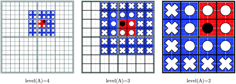
| NN(A) = {B: level (A) = level (B), |C(A) − C(B)| ≤ r(A) + r(B)}. | (15) |
Note that A is itself a member of NN(A). The number of nearest neighbors ranges from 8 when A is in a corner to 27 when it is in the interior of the computational domain. The local far field of the Ath box, LFF(A), consists of all the children of the nearest neighbors of the parent of A, which are not nearest neighbors of A themselves:
 | (16) |
There are 43–33 = 37 to 63–33 = 189 boxes in the local far field of any box. From this definition we note that, for boxes at levels 0 and 1, the local far field is empty, because box 0 has no parent and no nearest neighbors.
An important property of this separation is that Ω(0) is exactly covered by the boxes in NN(A)∪LFF(A)∪LFF(parent(A))∪LFF(parent(parent(A)))∪…, for any box A. In this way, the complete domain can be partitioned into a hierarchy of non-overlapping domains,
 | (17) |
The decomposition in eqn (17) will always terminate with boxes at level two. The concepts defined in this section are illustrated in Fig. 3 in two dimensions, for Dmax = 4.
2.4 Grid representation
For each of the boxes at the highest level Dmax, an equidistant Cartesian grid is constructed as presented below. A more detailed discussion can be found elsewhere.42The one-dimensional grids consist of N points separated by a distance h, the grid step. For example, for the x dimension, the points are x(A)1 = x(A)min, x(A)2,…,x(A)N = x(A)max. A one-dimensional basis function is assigned to each point, e.g. χ(A,y)j(y) is assigned to point y(A)j. The basis functions are polynomials of degree P with small support around their grid points. We employ sixth-degree polynomials (P = 6) in the present work.
The three-dimensional basis set is an outer (tensorial) product of the one-dimensional local basis sets. The expansion coefficients are the values of the function in the corresponding grid points. Taking the density ρμ(r) as an example, its expansion in the local basis functions within box A is given by
 | (18) |
As we have shown before,35 this representation is adequate for smooth charge densities. For all-electron calculations, the presence of cusps at the nuclear positions requires a prohibitive number of points, which can be circumvented by explicitly representing those cusps, which is beyond the scope of the present work but has been described in detail in our previous work.42
The total number of grid points is given by (2DmaxN)3. Equivalently, this is (L/h)3, where L is the total length of the computational domain Ω(0). For a typical step of 0.1a0 and N = 200, Dmax = 3 allows treating the systems with a volume of up to 160 × 160 × 160a03.
2.5 The FMM energy expression
Using eqn (17), the expression for the energy in eqn (1) can be reorganized as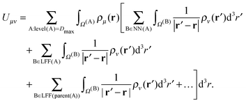 | (19) |
The contributions arising from the nearest neighbors are grouped together into the near-field interaction energy, U(A)NF. The remaining terms constitute the far-field interaction energy U(A)FF.
 | (20) |
 | (21) |
 | (22) |
Because all the density pairs contributing to the far-field energy are non-overlapping, U(A)FF can be calculated by exploiting the bipolar expansion in eqn (3) as
| U(A)FF = (q(A)μ)Tv(A)ν | (23) |
 | (24) |
 | (25) |
The final expression for the energy is then given by
 | (26) |
2.6 Parallelization
The linear scaling nature of the fast multipole method is apparent from eqn (26): for a given set of far field potential vectors and near field potentials, the energy is evaluated in a single loop over the boxes. For an analysis establishing linear scaling complexity also in the potential construction step, we refer to the work by White and Head-Gordon.31 Here, we focus on presenting the traditional FMM algorithm in a maximally parallel fashion.Each box A is assigned to a node, denoted with A. If the GB-FMM scheme is parallelized to the fullest, the number of computational nodes will be 82 + 83 +…+ 8Dmax. We will refer to the 8Dmax nodes at the highest level as near-field nodes. It is not required that all nodes should be physically different. For example, in the benchmarks shown in Section 3, all non-near-field nodes are in fact the same.
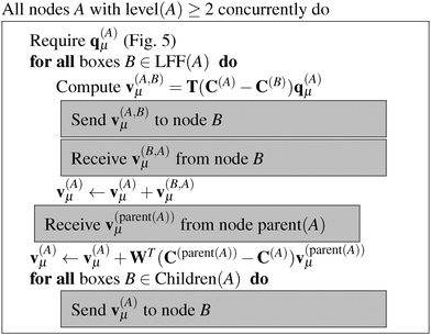
The algorithms required for the calculation of pair energies are represented in Fig. 4–8. The operations, which are run concurrently by all nodes, are represented within rectangles. The near-field nodes must often carry out additional steps, which are indicated separately. Grey rectangles indicate steps that require some type of inter-node communication.
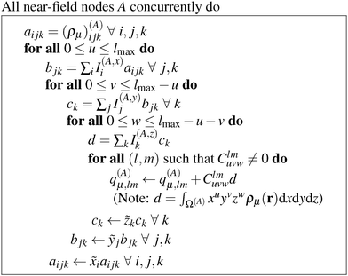 | ||
| Fig. 4 Algorithm for the numerical integration of the multipole moments of the boxes with level(A) = Dmax. | ||
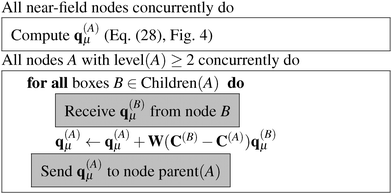 | ||
| Fig. 5 Algorithm for calculating q(A)μ, the multipole moments for all boxes at all levels greater or equal to two for a charge density ρμ. | ||
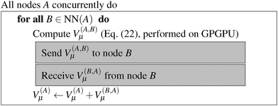 | ||
| Fig. 7 Algorithm for calculating V(A)μ(r), the nearest-neighbor contribution to the potentials in all boxes at the highest level. | ||
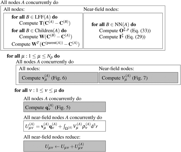 | ||
| Fig. 8 The grid-based FMM algorithm for the calculation of all pair interaction energies from Nρ charge densities. | ||
In order to carry out the necessary operations, each node A stores the center of its own box, C(A), and the centers of all its children, its parent and all boxes in LFF(A). In addition, each near-field node must also store the grids of its nearest neighbors (including its own), and be able to calculate or read the expansion coefficients (ρ(A)μ)ijk, which are the expansion coefficients of all the input densities in box A.
2.7 Evaluation of multipole moments
At the highest division level, the multipoles are integrated using the expression in eqn (24). The fact that the multipole moments have to be computed by numerical integration may seem daunting, especially when the multipole moments of Gaussian primitives can be evaluated more or less trivially.32 However, it turns out that the tensorial nature of the local basis functions leads to a very efficient algorithm, as the multipole moment integrals always separate to the products of one-dimensional integrals, many of which can be reused.The real solid harmonics can be expressed using Cartesian coordinates as
 | (27) |
 | (28) |
![[x with combining tilde]](https://www.rsc.org/images/entities/i_char_0078_0303.gif) i = x(A)i − C(A)x, ỹj = y(A)j − C(A)y and
i = x(A)i − C(A)x, ỹj = y(A)j − C(A)y and ![[x with combining tilde]](https://www.rsc.org/images/entities/i_char_0078_0303.gif) i = z(A)k − C(A)z. The quantities I(A,x)i, I(A,y)j and I(A,z)k are one-dimensional integrals over the basis functions, e.g.
i = z(A)k − C(A)z. The quantities I(A,x)i, I(A,y)j and I(A,z)k are one-dimensional integrals over the basis functions, e.g. | (29) |
The most expensive operations appear in the outermost loops, with a computational cost that is asymptotically proportional to ![[scr O, script letter O]](https://www.rsc.org/images/entities/char_e52e.gif) ((lmax + 1)N3), which is a substantial improvement as compared to the cost of
((lmax + 1)N3), which is a substantial improvement as compared to the cost of ![[scr O, script letter O]](https://www.rsc.org/images/entities/char_e52e.gif) ((lmax + 1)2N3) for naive implementation.
((lmax + 1)2N3) for naive implementation.
For the boxes at lower levels, the multipole moments can be computed recursively from the multipoles of their children using eqn (8):
 | (30) |
The algorithm to compute the multipole moments at all boxes is outlined in Fig. 5. Initially, all near-field nodes must integrate the multipole moments in their respective boxes as described above. Then, the boxes at lower levels can recursively reconstruct their multipole moments. For each of its 8 children, each node receives the (lmax + 1)2 entries of the multipole moment vector, which is then multiplied by the (lmax + 1)2 × (lmax + 1)2 translation matrix, and the result is accumulated into q(A)μ. In the FMM literature, this step is often referred to as the upward pass.
Once the multipole moments have been obtained, the corresponding potential vectors v(A)μ are computed using the algorithm described in Fig. 6. Each node computes its contribution to the potential in each box B of LFF(A). This computational step consists of a series of constructions of interaction matrices and the corresponding matrix–vector multiplications with a cost of ![[scr O, script letter O]](https://www.rsc.org/images/entities/char_e52e.gif) (lmax4). The resulting potential vectors, containing (lmax + 1)2 entries each, are then sent to the appropriate nodes B. In this way, each node receives all the necessary contributions which are added up to form the local far-field contribution to v(A)μ. Then, starting from the lowest level, which is level 2 in practice as the contributions from levels 0 and 1 vanish, because they have no local far field neighbors. Each node sends v(A)μ to its children, which translate the contribution by means of eqn (9) and accumulate it into their own v(A)μ, which is commonly known as the downward pass.
(lmax4). The resulting potential vectors, containing (lmax + 1)2 entries each, are then sent to the appropriate nodes B. In this way, each node receives all the necessary contributions which are added up to form the local far-field contribution to v(A)μ. Then, starting from the lowest level, which is level 2 in practice as the contributions from levels 0 and 1 vanish, because they have no local far field neighbors. Each node sends v(A)μ to its children, which translate the contribution by means of eqn (9) and accumulate it into their own v(A)μ, which is commonly known as the downward pass.
2.8 Calculation of the direct interactions
For the direct interactions, we use a low-rank separated representation of the Coulomb potential based on the well-known integral expression by Boys and Singer:43,44 | (31) |
We refer to our previous work for further details on how to obtain the quadrature weights ωp and points tp.35 In this work, the operator rank is R = 50 and the chosen quadrature parameters are tl = 2, tf = 50, Nlin = 25, and Nlog = 25. The parameters are chosen such that the accuracy of the near-field interactions is not a bottleneck. Thus, in practical applications the total number of quadrature points can be significantly reduced.
The calculation of the contributions to the potential of the nearest neighbors in eqn (22) is done as a series of tensor contractions:
 | (32) |
The linear transformation is executed very efficiently using GPGPUs, as we have recently shown.15 The performance obtained on a single Nvidia K40 card is between 0.5 and 1 TFLOPs depending on the size of the matrices Oξ,p.
The matrix elements of the Oξ,p matrices are given by
 | (33) |
The algorithm to compute the near-field potentials is summarized in Fig. 7. Each near-field node computes all contributions in their neighbor boxes and sends the data to the neighbor nodes. The computation itself is carried out very efficiently on the GPGPU. The inter-node communication can be expensive: the majority of the nodes have to send and receive 27N3 coefficients, which for typical values of N = 100–200 amounts from hundreds of MB to over 1 GB for 64-bit floating point numbers.
The near-field energy contribution to the energy in eqn (26) is then computed as
 | (34) |
2.9 Calculation of pair interactions
We are now ready to put together all the pieces introduced in this Section into an overall algorithm that computes all pair energies. The final algorithm is presented in Fig. 8. In the initialization step, all nodes compute the translation and interaction matrices that they need. Near-field nodes also compute the necessary Coulomb matrices and the integral vectors. Then, for each input density, each node computes the necessary potential vectors (v(A)μ) and the potential contributions (V(A)μ(r)) of the near-field nodes. For each density ρν(r) with 1 ≤ ν ≤ μ, the node computes its contribution to the interaction energy Uμν, either as the dot product (q(A)μ)Tv(A)ν or using the tensor contraction in eqn (34) for the near-field nodes. All contributions are added up into a master node.3 Results
3.1 Benchmark calculations on fullerene systems
The accuracy and parallel performance of the GB-FMM scheme were analyzed in a series of benchmark calculations on fullerene structures that were obtained from Mitsuho Yoshida's fullerene library database.45 We constructed model densities from linear combinations of Gaussian functions centered on the nuclear coordinates of the fullerene structures: | (35) |
The densities were partitioned to the boxes at the highest level of division. For example, when Dmax = 3, the density was represented as an array of size 83 = 512 containing function objects. These objects contained in turn the information about the near field grids and the numerical meshes. The use of densities of the form in eqn (35) permitted us to determine the accuracy of the GB-FMM scheme. The so-called self-interaction energy of the charge density (eqn (1) in the case μ ≡ ν) was computed and compared with its analytical value. The analytical value was obtained as
 | (36) |
The Gaussian amplitudes were set to the nuclear charge of carbon, qK ≡ 6, and the exponents were set to unity, αK ≡ 1. These parameters ensured that the charge was reproduced and, more importantly, that all model charge densities were globally smooth.
The GB-FMM scheme was implemented in Fortran and parallelized with MPI and cuBLAS, the CUDA-implementation of the BLAS library. One single-core physical node was responsible for computing the far-field potentials with the FMM, while the near field potential calculations were divided among hybrid nodes, each equipped with a GPGPU card (NVIDIA Tesla 40 K cards that are controlled by Intel Xeon E5-2620-v2 CPUs). All parallel runs were performed on the Taito GPGPU cluster of the CSC computing center.
3.2 Accuracy
The fullerene C60 was picked as the test structure for studying how the accuracy of the GB-FMM scheme depends on the grid step h, the truncation of the multipole expansion lmax, and the depth of the octree Dmax. The domain size was adjusted for ensuring that the density was negligible at the domain boundaries. In the case of C60, the cubic domain had a side length of 24a0. The values Dmax = 2, 3, 4 and lmax = 5, 7, 10, 12, 15 were considered. The grid step was set to h = a0/2i with i = 1, 2, 3, 4.In Fig. 9, the absolute error in the self-interaction energy is plotted against the grid refinement parameter i. The error is seen to be saturated below one millihartree in the case of Dmax = 2, while the 10−5Eh level is reached with Dmax = 3 and Dmax = 4. These absolute energies translate to relative accuracies in the range of 1–10 ppb, which agree well with our previous results.34,35
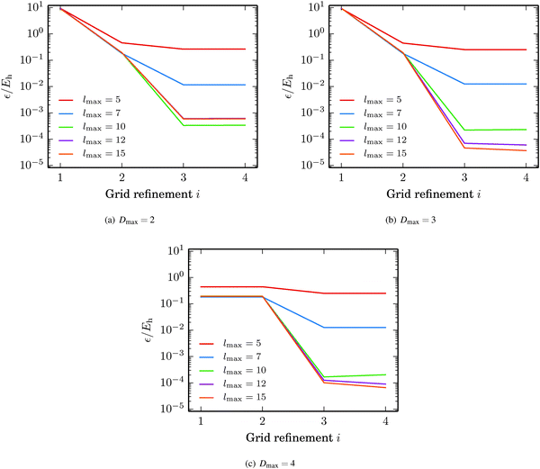 | ||
| Fig. 9 Accuracy of the GB-FMM with respect to grid quality, truncation of the multipole expansion and the depth of the octree. The grid refinement parameter i gives the grid step from h = a0/2i. | ||
The error in the energy saturates with respect to both the truncation of the bipolar multipole expansion lmax and the grid step h, which implies that the remaining error results from the quadrature parameters of the direct integration, e.g., the discrete representation of the Coulomb operator.
3.3 Performance
The evaluation of the electrostatic potential is by far the most time consuming step in the GB-FMM scheme. As the near-field and far-field potentials are computed concurrently by construction, the timing is| tpot = max(tNF,tFF). | (37) |
The near-field contribution is 8DmaxtDAGE, where tDAGE is the time for constructing a single near field potential with the direct integration. The far-field contribution consists of evaluating the 8Dmax potential vectors, i.e., the expansion coefficients of the far-field potentials.
In Fig. 10, we report timings for calculation of the potentials for the C20, C60, C180, C320 and C720 systems together with the absolute relative error. The domain sizes varied between 18a0 × 19a0 × 18a0 and 59a0 × 56a0 × 56a0. The GB-FMM specific parameters were Dmax = 3 and lmax = 15. The grid step and the quadrature parameters were set to 0.1a0 and Nlin = Nlog = 25, respectively.
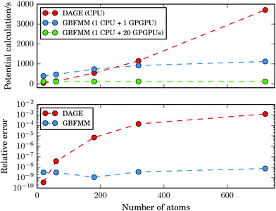 | ||
| Fig. 10 Time of the potential calculation as a function of system size. The data points correspond to the fullerene structures C20, C60, C180, C320 and C720. | ||
While the cost of the direct integration of the potential on a single-core CPU is competitive with the GB-FMM part for small systems, the GB-FMM scheme scales significantly better with the size of the system, both in terms of accuracy and performance. In the GB-FMM calculation, a constant, ppb-level relative accuracy is obtained for all system sizes, whereas the accuracy of the direct numerical integration deteriorates with increasing size of the domain.
The results obtained for the GB-FMM scheme can be expected, as the accuracy of the scheme should not depend on the size of the computational domain, because the entire domain is never simultaneously considered. In addition, as all the direct numerical integration parts of the calculations within the GB-FMM scheme are performed on domain sizes of a couple of atomic units per side, the GB-FMM should retain the accuracy characteristic (0.1–1 ppb) of the direct numerical integration for that size of the grid.
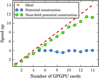
When the near field potential calculation is distributed among 20 GPGPU nodes, the GB-FMM scheme is clearly superior to the fully numerical integration method and exhibits effectively constant scaling of the computational time with respect to system size, which is a consequence of reaching the limit of Amdahl's law. When all GPGPU nodes performing the numerical integration complete their task faster than the CPU performing GB-FMM calculation, the running time of the potential calculation is dominated by the single-core GB-FMM part of the calculation. The calculation can be speeded up by also distributing the GB-FMM part on several CPUs or GPGPUs.
Fig. 11 shows in detail how the limit of Amdahl's law is reached for the C60 system. The employed parameters were the same as used in the calculations reported in Fig. 10. With lmax = 15 and Dmax = 3, the GB-FMM part becomes the bottleneck when the near field potential calculations are divided among four to five nodes. The calculations of the near-field potentials scale nearly ideally as expected.
4 Conclusions and outlook
A grid-based fast multipole method (GB-FMM) scheme for calculating two-electron interaction energies has been developed and implemented. The computational domain is divided into subdomains that can be assigned to nearest neighbors and more distant subdomains. The far-field contributions to the two-electron interaction energies are obtained by employing the bipolar series expansion of the Coulomb operator, whereas the near-field contributions are obtained by fully numerical integration of the corresponding Coulomb energy integral. In the GB-FMM scheme, the multipole moments are calculated for the individual subdomains and combined to multipole moments for groups of subdomains. The series expansions of the charge density and the electrostatic potential are combined to yield the electrostatic interaction energy of separated non-overlapping charge densities. The numerical integration algorithm has been adapted for general purpose graphics processing (GPGPU) units. The performance of the computational scheme has been demonstrated by calculations using one CPU for the serial part including the GB-FMM and up to 20 GPGPUs for the numerical integration of the Coulomb energy. For the largest GPGPU cluster, the parallel part of the code is faster than the serial one and since the computing time of the serial part of the code is more or less independent of the system size, the computational time is found to be independent of the size of the system. The present calculations show that numerical calculations using local basis functions can be made to run very efficiently on massively parallel computers, because for local basis functions the computational domain can be easily subdivided into smaller units whose interactions can be computed independently. The algorithm yields a computational method that formally scales linearly with the system size, whereas the massively parallel computer architecture renders calculations whose wall time is independent of the system size feasible. The scalability, performance and accuracy of the present numerical calculations on the GPGPU cluster suggest that quantum chemistry calculations of the future will most likely be made this way using local basis functions.Appendix A
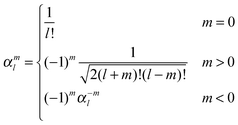
The interaction and translation matrices
Introducing the auxiliary functions | (38) |
 | (39) |
 | (40) |
 | (41) |
 | (42) |
 | (43) |
 | (44) |
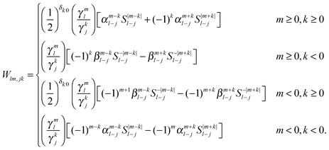 | (45) |
Acknowledgements
This work was supported by the Academy of Finland through projects (137460 and 275845) and its Computational Science Research Programme (LASTU/258258) and by the Magnus Ehrnrooth Foundation. CSC – the Finnish IT Center for Science – is acknowledged for computer time. We thank Jonas Jusélius for support with the development and maintenance of the numerical code.References
- G. E. Moore, Electron. Mag., 1965, 38 Search PubMed.
- A. V. Titov, I. S. Ufimtsev, N. Luehr and T. J. Martinez, J. Chem. Theory Comput., 2013, 9, 213–221 CrossRef CAS.
- K. Bhaskaran-Nair, W. Ma, S. Krishnamoorthy, O. Villa, H. J. J. van Dam, E. Aprà and K. Kowalski, J. Chem. Theory Comput., 2013, 9, 1949–1957 CrossRef CAS.
- J. E. Stone, J. C. Phillips, P. L. Freddolino, D. J. Hardy, L. G. Trabuco and K. Schulten, J. Comput. Chem., 2007, 28, 2618–2640 CrossRef CAS PubMed.
- K. Yasuda, J. Comput. Chem., 2008, 29, 334–342 CrossRef CAS PubMed.
- J. A. Anderson, C. D. Lorenz and A. Travesset, J. Comput. Phys., 2008, 227, 5342–5359 CrossRef PubMed.
- L. Vogt, R. Olivares-Amaya, S. Kermes, Y. Shao, C. Amador-Bedolla and A. Aspuru-Guzik, J. Phys. Chem. A, 2008, 112, 2049–2057 CrossRef CAS PubMed.
- M. S. Friedrichs, P. Eastman, V. Vaidyanathan, M. Houston, S. Legrand, A. L. Beberg, D. L. Ensign, C. M. Bruns and V. S. Pande, J. Comput. Chem., 2009, 30, 864–872 CrossRef CAS PubMed.
- J. van Meel, A. Arnold, D. Frenkel, S. Portegies Zwart and R. Belleman, Mol. Simul., 2008, 34, 259–266 CrossRef CAS PubMed.
- A. Asadchev, V. Allada, J. Felder, B. M. Bode, M. S. Gordon and T. L. Windus, J. Chem. Theory Comput., 2010, 6, 696–704 CrossRef CAS.
- R. Olivares-Amaya, M. A. Watson, R. G. Edgar, L. Vogt, Y. Shao and A. Aspuru-Guzik, J. Chem. Theory Comput., 2010, 6, 135–144 CrossRef CAS.
- B. G. Levine, D. N. LeBard, R. DeVane, W. Shinoda, A. Kohlmeyer and M. L. Klein, J. Chem. Theory Comput., 2011, 7, 4135–4145 CrossRef CAS.
- X. Wu, A. Koslowski and W. Thiel, J. Chem. Theory Comput., 2012, 8, 2272–2281 CrossRef CAS.
- S. A. Maurer, J. Kussmann and C. Ochsenfeld, J. Chem. Phys., 2014, 141, 051106 CrossRef CAS PubMed.
- S. Losilla, M. A. Watson, A. Aspuru-Guzik and D. Sundholm, J. Chem. Theory Comput., 2015, 11, 2053–2062, DOI:10.1021/ct501128u.
- K. Yasuda and H. Maruoka, Int. J. Quantum Chem., 2014, 114, 543–552 CrossRef CAS PubMed.
- G. M. Amdahl, Proc. of the AFIPS ’67 Spring Joint Computer Conference, 1967, pp. 483–485.
- C. F. Fischer, Hartree–Fock Method for Atoms. A Numerical Approach, Wiley, New York, USA, 1977 Search PubMed.
- T. Koga, S. Watanabe, K. Kanayama, R. Yasuda and A. J. Thakkar, J. Chem. Phys., 1995, 103, 3000–3005 CrossRef CAS PubMed.
- L. Laaksonen, P. Pyykkö and D. Sundholm, Comput. Phys. Rep., 1986, 4, 315–344 CrossRef.
- J. Kobus, L. Laaksonen and D. Sundholm, Comput. Phys. Commun., 1996, 98, 346–358 CrossRef CAS.
- F. Jensen, Theor. Chim. Acta, 2005, 113, 187–190 CrossRef CAS PubMed.
- F. A. Bischoff, R. J. Harrison and E. F. Valeev, J. Chem. Phys., 2012, 137, 104103 CrossRef PubMed.
- F. A. Bischoff and E. F. Valeev, J. Chem. Phys., 2013, 139, 114106 CrossRef PubMed.
- J. M. Pérez-Jordá and W. Yang, J. Chem. Phys., 1997, 107, 1218–1226 CrossRef PubMed.
- C. H. Choi, K. Ruedenberg and M. S. Gordon, J. Comput. Chem., 2001, 22, 1484–1501 CrossRef CAS PubMed.
- M. A. Watson, P. Saek, P. Macak and T. Helgaker, J. Chem. Phys., 2004, 121, 2915–2931 CrossRef CAS PubMed.
- H. Dachsel, J. Chem. Phys., 2010, 132, 119901 CrossRef PubMed.
- E. Rudberg and P. Sałek, J. Chem. Phys., 2006, 125, 84106 CrossRef PubMed.
- L. Greengard and V. Rokhlin, J. Comput. Phys., 1987, 73, 325–348 CrossRef.
- C. A. White and M. Head-Gordon, J. Chem. Phys., 1994, 101, 6593–6605 CrossRef PubMed.
- C. A. White, B. G. Johnson, P. M. Gill and M. Head-Gordon, Chem. Phys. Lett., 1994, 230, 8–16 CrossRef CAS.
- D. Sundholm, J. Chem. Phys., 2005, 122, 194107 CrossRef CAS PubMed.
- J. Jusélius and D. Sundholm, J. Chem. Phys., 2007, 126, 094101 CrossRef PubMed.
- S. A. Losilla, D. Sundholm and J. Jusélius, J. Chem. Phys., 2010, 132, 024102 CrossRef CAS PubMed.
- S. A. Losilla and D. Sundholm, J. Chem. Phys., 2012, 136, 214104 CrossRef CAS PubMed.
- P. García-Risueño, J. Alberdi-Rodriguez, M. J. Oliveira, X. Andrade, M. Pippig, J. Muguerza, A. Arruabarrena and A. Rubio, J. Comput. Chem., 2014, 35, 427–444 CrossRef PubMed.
- J. Kussmann, M. Beer and C. Ochsenfeld, Wiley Interdiscip. Rev.: Comput. Mol. Sci., 2013, 3, 614–636 CrossRef CAS PubMed.
- B. C. Carlson and G. S. Rushbrooke, Cambridge Philos. Soc. Proc., 1950, 46, 626–633 CrossRef.
- E. Steinborn and K. Ruedenberg, Adv. Quantum Chem., 1973, 7, 1–81 CrossRef CAS PubMed.
- T. Helgaker, P. Jrgensen and J. Olsen, Molecular Electronic-structure Theory, Wiley, New York, USA, 2000 Search PubMed.
- S. Losilla, M. Mehine and D. Sundholm, Mol. Phys., 2012, 110, 2569–2578 CrossRef CAS PubMed.
- K. Singer, Proc. R. Soc. A, 1960, 258, 412–420 CrossRef CAS.
- S. F. Boys, Proc. R. Soc. A, 1960, 258, 402–411 CrossRef.
- S. Weber, Mitsuho Yoshida's Fullerene Library, http://www.jcrystal.com/steffenweber/gallery/Fullerenes/Fullerenes.html.
Footnote |
| † Present address: Department of Chemistry, University of Aarhus, DK-8000 Aarhus C, Denmark. E-mail: sergio@chem.au.dk. |
| This journal is © the Owner Societies 2015 |


