Sustainable carbon materials
Maria-Magdalena
Titirici
*a,
Robin J.
White
b,
Nicolas
Brun
c,
Vitaliy L.
Budarin
d,
Dang Sheng
Su
e,
Francisco
del Monte
f,
James H.
Clark
d and
Mark J.
MacLachlan
g
aQueen Mary University of London, School of Engineering and Materials Science, Mile End Road, E14NS, London, UK. E-mail: m.m.titirici@qmul.ac.uk
bInstitute for Advanced Sustainability Studies, Berliner Str. 130, D-14467 Potsdam, Germany
cInstitut Charles Gerhardt de Montpellier, UMR 5253, CNRS-ENSCM-UM2-UM1, Université Montpellier 2, CC 1701, Place Eugène Bataillon, 34095 Montpellier, France
dGreen Chemistry Centre of Excellence, University of York, Department of Chemistry, Heslington, York, North Yorkshire YO10 5DD, UK
eShenyang National Laboratory for Materials Science, Institute of Metal Research, Chinese Academy of Science, Shenyang 110016, China
fInstituto de Ciencia de Materiales de Madrid, CSIC, Sor Juana Inés de la Cruz, 3, 28049 Madrid, Spain
gThe University of British Columbia, Department of Chemistry, 2036 Main Mall, Vancouver, BC V6T 1Z1, Canada
First published on 10th October 2014
Abstract
Carbon-based structures are the most versatile materials used in the modern field of renewable energy (i.e., in both generation and storage) and environmental science (e.g., purification/remediation). However, there is a need and indeed a desire to develop increasingly more sustainable variants of classical carbon materials (e.g., activated carbons, carbon nanotubes, carbon aerogels, etc.), particularly when the whole life cycle is considered (i.e., from precursor “cradle” to “green” manufacturing and the product end-of-life “grave”). In this regard, and perhaps mimicking in some respects the natural carbon cycles/production, utilization of natural, abundant and more renewable precursors, coupled with simpler, lower energy synthetic processes which can contribute in part to the reduction in greenhouse gas emissions or the use of toxic elements, can be considered as crucial parameters in the development of sustainable materials manufacturing. Therefore, the synthesis and application of sustainable carbon materials are receiving increasing levels of interest, particularly as application benefits in the context of future energy/chemical industry are becoming recognized. This review will introduce to the reader the most recent and important progress regarding the production of sustainable carbon materials, whilst also highlighting their application in important environmental and energy related fields.
1. Introduction
To address and meet the challenges presented by the global energy demand of an ever increasing population and associated environmental consequence of a still generally fossil fuel-based society, very innovative, efficient and increasingly sustainable solutions must be found.1 In this regard, there are several options by which to generate and store renewable energy from sun, wind, water, geothermal or biomass – all of which are heavily reliant on materials technologies to allow for their efficient implementation. Therefore, the development of sustainable materials is extremely important.2 This is not a trivial task as these new materials should also ideally be low cost, scalable, industrially and economically attractive, and based on renewable and highly abundant resources, whilst of course achieving application performances in renewable energy conversion or environmental applications that exceed existing technologies. Therefore, it is the materials scientist's duty to develop novel, high performance and sustainable materials to solve the challenge of providing renewable energy for all whilst limiting environmental impacts.In the context of sustainable materials development, after oxygen, carbon is the most abundant element in the biosphere. Nature utilizes these elements coupled with hydrogen to provide the basis for renewable energy storage (e.g., carbohydrates). Analogously, carbon-based systems are increasingly performing a major role in emerging renewable energy conversion technologies: electrodes in energy storage devices, electrocatalysis, photocatalysis, heterogeneous catalysis, biofuels, etc.3 Carbon materials are also extensively used in water purification, gas separation (e.g., CO2 capture)/storage, and as a soil additive. Furthermore, the importance and potential of carbon-based materials has been recognized in recent decades by some of the highest scientific awards including the 1996 Nobel Prize in Chemistry (fullerenes), the 2008 Kavli Prize in Nanoscience (carbon nanotubes), and the 2010 Nobel Prize in Physics (graphene). As a consequence, interest in carbon-based materials and their applications is encountering its most rapid development and represents a very important topic in modern materials science.
Concurrently with the creation of fossil fuel-based industry since the start of the 21st century, the majority of carbon-based materials are conventionally synthesized using fossil-derived precursors and often require harsh or energy intensive synthetic conditions (e.g., electric-arc discharge techniques, chemical vapour deposition (CVD), etc.) It is also vital to underline the importance of optimizing surface area and porosity of materials for catalytic, separation and energy applications.
One popular synthetic route to high surface area, porous carbon materials is the nano-casting approach, but this has its limitations (e.g., multistep synthesis involving a sacrificial inorganic template).4–6 The synthesis of such “hard templated” (meso)porous carbons can use potentially sustainable precursors (e.g., sucrose in CMK-1 synthesis) but generally carbon materials and the aforementioned carbon allotropes (e.g., nanotubes) are not derived from sustainable resources and require complex synthetic approaches that are difficult to scale and usually lead to condensed, hydrophobic carbon structures.4–8 Most of these structures are not suitable for future chemical/energy provision schemes (e.g., the aqueous phase-based biorefinery).9–11 Renewable resource-derived carbons have until relatively recently concerned only activated carbons (ACs).12–15 This class of predominantly microporous materials is commercially available and has proven application in water treatment,16,17 CO2 capture,18 energy storage (e.g., supercapacitors19), and perhaps most typically heterogeneous catalysis.20,21 However, the top-down approach to the synthesis of ACs from natural precursors does not provide the necessary control over material features including porosity, morphology and surface chemistry, whilst limited batch-to-batch reproducibility, final carbonization yield and the use of harsh reagents during synthesis (i.e., strong acids or bases) to generate porosity are other significant process drawbacks.
Conversely, the development of more flexible routes to new carbon materials derived from renewable resources has only recently become a topic of significant interest. It is perhaps appropriate to note that the materials chemist can draw inspiration from a variety of natural processes (e.g., coalification, photosynthesis) and structures (e.g., crustacean shells, plant tissues, etc.) to produce the variety of complex nanostructured materials needed to address the energy and chemical challenges of a future sustainable society. Importantly, the new structures may also be derived from renewable, abundant carbon-based precursors that are not in competition with food suppliers. Such examples include lignocellulosic biomass or other products contained in food/agricultural waste (i.e., carbohydrates, cellulose, hemicellulose, lignin, chitin, inorganics, proteins, etc.) In this context, this review aims to introduce the reader to the latest progress in the synthesis of carbon materials from renewable precursors via processes conforming to the principles of Green Chemistry. The latest trends in the synthesis, characterisation and applications of these novel carbon materials are presented via a collaboration of some of the most prominent contributors to the development of this rapidly expanding field, underlining the modern day necessity of global networks to generate innovative solutions for a sustainable future and a clean environment – and in a more a specific context here, a sustainable future for carbon materials science.
2. Graphitic nanostructures
Typical graphitic nanostructures include carbon nanotubes (CNTs), carbon nanofibers (CNFs), graphene, graphene oxides, carbon nanohorns, onion-like carbon (OLC), and grapheme dots. They may be prepared using various carbon sources with different methods. We focus here mainly on the preparation of CNTs and graphene with renewable materials as carbon source or using “greener” processes.2.1 Carbon nanotubes and related structures
CNT is perhaps the most representative example of carbon-based nanomaterials22 for which many excellent properties have been described.23 The growth mechanism of CNTs has been intensively investigated and was described to a large extent.23,24 Based on well-established and commonly used CVD processes, CNTs are prepared from a carbon source and catalyst particles (usually metal or mixed metal particles) capable of decomposing the carbon-containing molecules.25 The search for the most efficient carbon source and associated catalyst has been the most important driving force in CNT science and technology, with the aim to obtain high yields and high quality “pristine” CNTs with the desired diameters and wall layers. Synthetic catalysts (using metal salts as precursors) and volatile precursors (e.g., methane, acetylene, benzene, xylene, toluene, etc.) are commonly used in CVD processes. In the context of sustainable carbon materials, a number of research works highlight the use of metal particles derived from natural materials, and application of alternative carbon sources, for instance from renewable sources, for CNT production,26 with the ultimate aim in many cases to reduce the overall CNT production cost and enhance the environmental/sustainability of the process (e.g., for mass production).Single walled CNTs (SWCNTs) have only one wall and require smaller catalysts than those used in MWCNT synthesis.24 Kawasaki et al. demonstrated that SWCNTs with diameters in the range of 5–20 nm can be grown on the natural minerals magnesite (MgCO3) and brucite (Mg(OH)2) by pyrolysis of methane gas.32 Differing from the above mentioned volcanic rock or red soil with more than 10 wt% iron oxide content, both magnesite from Brazil and brucite from the USA contain only trace amounts of iron oxide – 0.339 wt% and 0.105 wt%, respectively. The trace amounts of Fe in magnesite and brucite allow the formation of small catalyst particles that are capable of catalysing the growth of SWCNTs. Forsterite from North America and diopside from Pakistan containing ca. 2 wt% iron were found to be incapable of catalysing SWCNT formation.
Due to the broad and mostly uncontrolled size-distribution of the CNTs (i.e., from a few nanometers to several micrometers) and the heterogeneity of the chemical environment of Fe, it could be assumed that it would be difficult to use natural mineral catalysts to obtain CNTs with uniform morphology and microstructure. A recent work of Serp's group,31 demonstrated that red volcanic rocks from the island of Santorini (Greece) were capable of catalysing the formation of a mixture of CNTs and CNFs with a highly heterogeneous diameter distribution (5–150 nm), but a significant number of thin MWCNTs were also produced with inner and outer diameters of 2–5 and 5–7 nm, respectively, corresponding to 3–6 walls (Fig. 1). Their detailed analysis,31 revealed that the presence of iron titanate crystals in some volcanic rocks was responsible for the preferential formation of thin MWCNTs on this catalyst. Following this observation, a synthetic catalyst combining Fe–Mo deposited on a TiO2-modified alumina support was prepared by the same group, which led to a reduction in CNT wall thickness compared to the FeMo–Al2O3 system without TiO2 modification (under the same reaction conditions). The significance of this work originates from the use of a natural catalyst for CNT synthesis, which acted as an inspiration for an original geo-mimetic approach to produce highly selective catalysts for thin-walled CNT synthesis.31
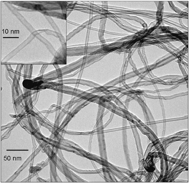 | ||
| Fig. 1 Low resolution TEM images of carbon nanotubes produced from the red stone (reprinted with permission from Bacsa et al.31). | ||
Iron is a biologically essential element and is ubiquitous in living systems. Some plant tissues are rich in iron33 and can be used for nanocarbon synthesis.34 Differing from iron found in the above-mentioned volcanic rock or minerals, the content of iron in a single cell of a plant is uniform. When used in nanocarbon synthesis, each catalyst particle arising from the metal content of a single cell of the precursor may have identical size and composition. Zhao et al. explored the use of cloud ear fungus and black sesame seeds as catalyst precursors to prepare CNTs using liquefied petroleum gas as carbon source. The cloud ear fungus and black sesame seeds must be washed, de-liquored, air-dried and pulverized before use. CNTs were produced through CVD at 800 °C in a relatively high yield and of a uniform size distribution featuring no amorphous carbon as a side product – a particularly encouraging result from an industrial viewpoint.35
Derivatives of biomass have also been used both as catalyst and catalyst-support for CNT production. Biomass-derived active carbon (AC) typically contains iron. Chen et al., revealed that the intrinsic iron content of biomass-derived ACs (especially from palm kernel shell (AC-P), coconut (AC-C), and wheat straw (AC-W)) can be directly used as a catalyst for CNF synthesis.34 Also here, a pre-reduction with H2 is necessary to activate the catalyst imbedded in the AC. When carbon is used as a support, the quality of the obtained nanocarbon depends strongly on the degree of graphitisation.36
![[thin space (1/6-em)]](https://www.rsc.org/images/entities/char_2009.gif) :
:![[thin space (1/6-em)]](https://www.rsc.org/images/entities/char_2009.gif) H ratio (e.g., palm oil (C55H100O6); C
H ratio (e.g., palm oil (C55H100O6); C![[thin space (1/6-em)]](https://www.rsc.org/images/entities/char_2009.gif) :
:![[thin space (1/6-em)]](https://www.rsc.org/images/entities/char_2009.gif) H = 1
H = 1![[thin space (1/6-em)]](https://www.rsc.org/images/entities/char_2009.gif) :
:![[thin space (1/6-em)]](https://www.rsc.org/images/entities/char_2009.gif) 2), suggesting the potential of renewable carbon-based resources in CNT production. As an alternative to CVD, spray-pyrolysis is often used for the processing of liquid precursors whereby pyrolysis of the carbon precursor and deposition occur in one step at high temperature. In CVD processes, the liquid carbon precursor must first be vapourised at low temperature in one furnace and pyrolysised at higher temperature in a second furnace containing the catalyst, with the vapour transported by a carrier gas. In this context, vegetable oil is one choice of liquid carbon source from biomass, as the high carbon content can produce large amounts of high-quality CNTs with high purity. Turpentine oil (C10H16),37,38 eucalyptus (C10H18O),39 coconut,40 neem,41 and palm oil42–44 have also been used as the carbon source for CNTs production. In a spray pyrolysis process with carefully designed Fe/Co zeolite catalysts and eucalyptus oil as carbon source, Ghosh et al. successfully synthesized SWCNTs of diameter of ca. 0.79–1.71 nm.39 When this vegetable oil is pre-mixed with ferrocene, aligned MWCNTs can also be produced.
2), suggesting the potential of renewable carbon-based resources in CNT production. As an alternative to CVD, spray-pyrolysis is often used for the processing of liquid precursors whereby pyrolysis of the carbon precursor and deposition occur in one step at high temperature. In CVD processes, the liquid carbon precursor must first be vapourised at low temperature in one furnace and pyrolysised at higher temperature in a second furnace containing the catalyst, with the vapour transported by a carrier gas. In this context, vegetable oil is one choice of liquid carbon source from biomass, as the high carbon content can produce large amounts of high-quality CNTs with high purity. Turpentine oil (C10H16),37,38 eucalyptus (C10H18O),39 coconut,40 neem,41 and palm oil42–44 have also been used as the carbon source for CNTs production. In a spray pyrolysis process with carefully designed Fe/Co zeolite catalysts and eucalyptus oil as carbon source, Ghosh et al. successfully synthesized SWCNTs of diameter of ca. 0.79–1.71 nm.39 When this vegetable oil is pre-mixed with ferrocene, aligned MWCNTs can also be produced.
Camphor (C10H16O) is crystallized latex sourced from the Cinnamomum camphora tree, which abundantly grows in almost all sub-tropical countries including parts of China, India and Japan. Approximately 3 tonnes of camphor can be extracted from a single matured tree. With a special, but quite simply designed set-up (camphor needs to be vaporized), Kumar and Ando demonstrated that camphor could be used to produce CNTs in large quantities. A nanotube garden containing single-wall, multi-wall and aligned-CNTs was produced from thermal decomposition of camphor under Ar at 875 °C. An extremely low catalyst amount can be used when camphor acts as the carbon source whilst amorphous carbon formation was found to almost nil, eliminating the need for post-deposition heat treatment.45 Like vegetable oil, chicken fat has a high C content and a low C![[thin space (1/6-em)]](https://www.rsc.org/images/entities/char_2009.gif) :
:![[thin space (1/6-em)]](https://www.rsc.org/images/entities/char_2009.gif) H ratio. Chicken fat oil,46 when mixed with ferrocene as precursors, has been used for CNT growth. Suriani et al. demonstrated that vertically aligned CNTs (VACNTs) could be prepared on a mirror-polished p-type (100) Si wafer substrate. VACNTs with good crystallinity (ID/IG ratio of 0.63), a purity of 88.2%, and minimal amorphous carbon content were successfully synthesized. Chicken fat is not a renewable resource in the conventional sense, but waste chicken fat is a free source of carbon that is discarded during poultry processing. In addition, the utilization of chicken fat as a precursor for VACNTs production could be interesting in managing the disposal of chicken fat waste. If this method can successfully be established, it can be lead to product diversification beyond use in bio-diesel and bio-gas production.46
H ratio. Chicken fat oil,46 when mixed with ferrocene as precursors, has been used for CNT growth. Suriani et al. demonstrated that vertically aligned CNTs (VACNTs) could be prepared on a mirror-polished p-type (100) Si wafer substrate. VACNTs with good crystallinity (ID/IG ratio of 0.63), a purity of 88.2%, and minimal amorphous carbon content were successfully synthesized. Chicken fat is not a renewable resource in the conventional sense, but waste chicken fat is a free source of carbon that is discarded during poultry processing. In addition, the utilization of chicken fat as a precursor for VACNTs production could be interesting in managing the disposal of chicken fat waste. If this method can successfully be established, it can be lead to product diversification beyond use in bio-diesel and bio-gas production.46
Besides the natural origin of CNT catalysts in various minerals accompanied by the use of gases to grow CNTs, the abundant and low cost transition-metal graphitization (i.e., Fe, Ni) at rather low temperature in combination with renewable precursors also represents a sustainable route towards the production of graphitic structures. Recently, Schnepp, Giordano and Glatzel published an original paper where they filled the cartridges of a commercial inkjet printer with a metal catalyst (iron(III) nitrate) precursor and printed two-dimensional, lateral patterns on clean cellulose paper (Fig. 2(A)). The paper can be shaped, processed, or simply folded to a desired three-dimensional structure (Fig. 2(D)). Final thermal conversion of this structure then leads to the reaction of the catalytic ink with the paper, thus creating in this case conductive structures of iron carbide in graphitic carbon (Fig. 2(B) and (E)). Cupper could also be deposited onto such carbonized patterns (Fig. 2(C)). The resulting graphitic carbon nanostructures show a great flexibility (Fig. 2(F)) All experiments were repeated in parallel with powdered microcrystalline cellulose instead of filter paper (using the same ink but simply soaking the cellulose powder) in order to establish whether this process can be scaled up to larger quantities and whether the actual fiber form of the cellulose is required, for example, as a structural template. This scaling was possible, and the cellulose powder proved to be a good model system. In situ TEM studies revealed that in a first step iron-containing nanoparticles are formed on the surface of the carbonized cellulose fibers, which then in a fast process convert the fibers into well-ordered crumpled and rolled graphite. The metallic iron-containing nanoparticles dissolve the amorphous carbon from cellulose and recrystallize it in the form of ordered graphene nanostructures with higher mechanical stability and electrical conductivity.47
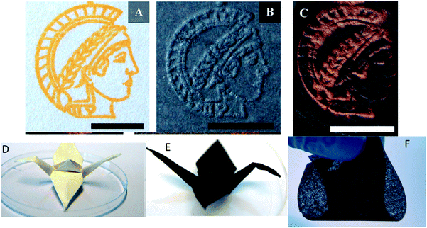 | ||
| Fig. 2 Preparation of the patterned carbons: printed sample (A), after calcination (B), after copper deposition (C); (the scale bar in each picture represents 1 cm); (D) folded origami crane; (E) folded origami after calcination under N2 flow; (F) example of a fully flexible sample derived from ultrathin paper. (Reproduced with permission from ref. 47.) | ||
Similarly, graphitic carbon nanostructures have been synthesized from cellulose by Sevilla via a simple methodology that essentially consists of the steps: (i) hydrothermal treatment of cellulose at 250 °C and (ii) impregnation of the carbonaceous product with a nickel salt followed by thermal treatment at 900 °C.48 The formation of graphitic carbon nanostructures seems to occur by a dissolution–precipitation mechanism in which amorphous carbon is dissolved in the catalyst nanoparticles and then precipitated as graphitic carbon around the catalyst particles. The subsequent removal of the nickel nanoparticles and amorphous carbon by oxidative treatment leads to graphitic nanostructures with a coil morphology. This material exhibits a high degree of crystallinity and large and accessible surface area.
An interesting and low cost approach to high quality multiwall carbon nanotubes was reported by Pol et al. who described a solvent-free process that converts polymer wastes such as low density and high-density polyethylene into multi-walled carbon nanotubes via thermal dissociation in the presence of chemical catalysts (cobalt acetate) in a closed system under autogenic pressure.49 Under such autogenic conditions polyolefins will reduce to carbon, further producing MWCNTs around the cobalt nanocatalyst obtained from the dissociation of CoAc. Given that polyethylene-based plastics need hundreds of years to degrade in atmospheric conditions and innovative solutions are required for polymer waste, this technology represents a very environmentally friendly and low cost method to produce CNTs.
2.2 Graphene
Graphene is a one atom thick planar sheet of sp2 bonded carbon atoms arranged in a honeycomb fashion. Several approaches have been reported in the literature for the preparation of graphene, including the exfoliation of graphite with ‘scotch tape’.50 CVD processes have also been developed but these approaches require expensive single crystal substrates and ultra-high vacuum. Complicated methods have to be developed to separate the graphene film from the substrate, leading to large area graphene films suitable for electronic applications. The chemical reduction of graphene oxide (GO)51 is one of the best established methods to make graphene on a large scale,52 but it is rather difficult to produce large-sized graphene by this process. Chemically reduced GO also suffers from the drawback of containing oxy moieties as impurities, which drastically affect the electronic properties of graphene. Despite these developments, a more cost-effective process that gives higher quality materials is still desired, and remains an outstanding challenge in materials science. Below are some of the notable attempts to overcome these barriers.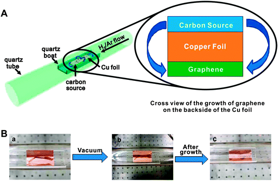 | ||
| Fig. 3 (A) Diagram of the experimental apparatus for the growth of graphene from food, insects, or waste in a tube furnace. On the left, the Cu foil with the carbon source contained in a quartz boat is placed at the hot zone of a tube furnace. The growth is performed at 1050 °C under low pressure with a H2/Ar gas flow. On the right is a cross sectional view that represents the formation of pristine graphene on the backside of the Cu substrate. (B) Growth of graphene from a cockroach leg. (a) One roach leg on top of the Cu foil. (b) Roach leg under vacuum. (c) Residue from the roach leg after annealing at 1050 °C for 15 min. Reprinted with permission from ref. 53. | ||
Zhu et al. reported that a sugar (e.g., glucose, fructose) can be used as a reducing agent to convert glucose oxide to graphene nanosheets (GNS) in an aqueous ammonia solution (Fig. 4).59 GO could be rapidly reduced in the presence of both glucose and ammonia, indicated by a solution colour change and spectroscopic methods during the reaction (i.e., from opaque brown to a dark, black colouration). The authors suggest that glucose, as an aldohexose, was first oxidized to aldonic acid by GO in the presence of ammonia solution. The aldonic acid is then converted to a lactone with the oxidized products containing a large number of hydroxyl groups and carboxyl groups. The reduced GO from this approach have some residual oxygen functionalities, such as the periphery carboxylic groups mentioned above. Thus, hydroxyl and carboxyl groups from the oxidized products of glucose can form hydrogen bonds with the residual oxygen functionalities of the reduced GO. Excess glucose was found to contribute to the stabilisation of the obtained GNS.
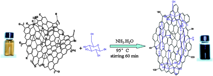 | ||
| Fig. 4 Illustration of the preparation of graphenes based on glucose reduction (reprinted with permission from Zhu et al.59). | ||
Dextran is a polysaccharide and one of the most widely used biocompatible biopolymers. Kim et al. have described an environmentally friendly approach for the synthesis of biocompatible reduced graphene oxide (RGO) by using dextran as a reducing agent and a surface functionalization agent.60 The obtained RGO is highly water-soluble and biocompatible and could be used for biological purpose. Green chemical approaches to the synthesis of biocompatible graphene were also reported using triethylamine61 or Ginkgo biloba extract62 as reducing and stabilizing agents. Glycine, a low price, environmentally friendly amino acid, has also been used in the reduction of GO, whereby the amine groups covalently interact with GO and, under reflux conditions, reduce GO to graphene.63 All the methods mentioned here are potentially cost-effective alternative routes to produce large-scale, RGO nanosheets.
2.3 Composite materials
Composite or hybrid materials consisting of more than two building blocks typically have enhanced properties as compared to the simple linear combination of the individual components. The combination of 1D or 2D building blocks can be used to produce hierarchical materials with multi-functionality. Among various building blocks, CNT and graphene are two of the most powerful materials that have been used in many composite materials.64,65 Nanocarbon composite or hybrid materials can be prepared or produced by various methods and have found many applications.66 Examples where one of the components is produced using either renewable or natural materials are briefly reviewed below.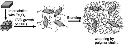 | ||
| Fig. 5 Growth procedure of CNTs on clay platelets and incorporation of CNT–clay hybrid filler into PA6 matrix for making the PA6/CNT–clay composite. Reprinted with permission from ref. 69. | ||
Wei's group has made outstanding progress regarding the preparation of hybrid composites consisting of alternating, vertically aligned CNTs between inorganic layers.70–72 Metal catalysts were prepared via the ion-exchange of iron into naturally existing layered vermiculites (from China) – a kind of layered double hydroxide. The vermiculites were exfoliated to speed up the ion exchange. CVD growth was conducted in a quartz reactor at high temperatures using diluted ethylene as the carbon source. It is interesting to note that the intercalated CNTs were vertically aligned. This phenomenon may be explained by the unique chemical environment of the layered compounds. For example, vermiculite exhibits a high-ion exchange capability.73 A higher number of the catalytic ions can be exchanged and absorbed within the layers, leading to a higher density of catalytic particles promoting the synchronous growth of aligned CNTs. The length and density of the aligned CNT arrays between the sheets are controllable, which allows for a periodic and hierarchical macrostructure with tailored interlayer distances. Other CNT-containing composites have also been prepared by CVD including CNT–AC composites that have been successfully used for removing chromate from aqueous solution.74
2.4 Applications
The graphitic carbon materials obtained with the aforementioned methods can be applied to applications most commonly associated with other carbon-based materials. For instance, CNTs/CNFs obtained using natural materials as catalyst precursors or carbon sources have been used as catalysts,30,76 and as energy/shock-absorbing materials.71 CNT–clay hybrids have been used as ideal filler for high-performance polymer nanocomposites. Zhang et al. prepared a PA6/CNT–clay composite by melt blending the CNT–clay hybrid with nylon-6 (PA6).69 Incorporation of only 1 wt% of the CNT–clay hybrid led to a significant improvement in the mechanical properties of PA6 with the tensile modulus and strength improving by 290% and 150%, respectively (as compared with neat PA6). The synergistic effect of the CNT–clay hybrid as a filler resulted in a homogeneous dispersion and an improved interface, and therefore a strong interaction with the polymeric matrix. Functional microporous conducting carbon synthesised by a single-step pyrolysis of dead neem leaves has produced useful electrode materials for high energy density supercapacitors.77 Graphene–sand composite can effectively remove contaminants from water.75 Some special bio-applications can be envisioned for graphene or RGO produced using green reducing agents (e.g., sugar) as they do not contain any toxic components and are therefore potentially more biocompatible.59,61–632.5 Perspectives on sustainable graphitic structures
It has been demonstrated that natural materials can be successfully used for the synthesis of graphitic nanomaterials, aimed at developing low cost, environmentally benign, and resource-saving processes for large-scale production. The presence of trace catalytically-active metals in natural materials is a prerequisite for this development. However, sustainability is not that straightforward and needs multiple discussions. Therefore we must take into account that such a natural product must be collected onsite, transported to the plant for crushing and sieving, and maybe purified before use in the CVD process, which may result in additional costs and energy consumption.Another disadvantage is that the amount of metals present in such natural materials is very low and the size of metal/metal oxide constituent grains in the minerals is the result of long geophysical or natural processes and therefore cannot be easily controlled. This will lead to unreproducible and uncontrolled CNTs. Therefore pre-treatments might be necessary to prevent such issues, involving additional costs, energy and harmful emissions. Of course, actions looking for natural minerals with proper amounts and suitable sizes of metal/metal oxide particles should be continued.
However, we must not neglect other research directions such as low cost and abundant transitional metals directing catalytic graphitization at low temperatures using low cost and renewable precursors. These have the potential to produce controlled and well defined graphitic nanostructures. Natural minerals as catalysts and supports are more suitable for production of CNTs for the applications in which the diameter requirement is not so strict, for example, in catalysis or as a catalyst support.
With respect to graphene, the biggest challenge at the moment is to produce it in large amounts with well-defined properties. This is particularly difficult, even when very precise tailor-made organic precursors are used in conjunction with CVD techniques. Obviously, using natural precursors and/or natural catalysts will make this task even more challenging. Therefore, graphene should perhaps only be used for those high-end applications where its exceptional physical properties (i.e., conductivity, flexibility, transparency and mechanical strength) are strictly necessary. Not every carbon-based product and device today must contain graphene. Applications such as electrodes in energy storage devices (batteries, supercapacitors, fuel cells) should perhaps make use of graphene composite materials that combine the exceptional properties of graphene, especially electronic conductivity, with those of other sustainable carbon materials (i.e., tailored porosities and functionality). Some of these sustainable alternatives will be described below.
3. Carbon materials from deep eutectic solvents (DES)
3.1 Synthesis of DES-derived porous carbons
One of the most common synthetic processes used for carbon preparation is the carbonization of polymers obtained by polycondensation between resorcinol and formaldehyde (RF).78–80 This process typically needs the presence of certain additives (e.g., block copolymers) if one desires to control the porous structure of the resulting carbon.81,82 This is by no means a trivial issue given that hierarchical structures – comprising both small (e.g., micro- and meso-) and large (e.g., macro-) pores have been proved more effective than non-hierarchical ones in most of the applications explored for carbons such as adsorbents, filters or electrodes.83–85 Unfortunately, the wasteful use of block copolymers as structure directing agents raises concerns about the overall greenness of such a material structuration approach. Recovery of the block copolymer after polycondensation (e.g., by extraction) and reuse could be an option, but this is often inhibited by diffusion of pseudo-high molecular weight substances through small pores or complex pore morphologies. Clearly, this lack of recovery has detrimental implications in terms of both atom economy and generation of waste after carbonization.The group of del Monte has recently demonstrated the use of different eutectic mixtures (so-called deep eutectic solvents or DESs)88 as interesting alternatives for the synthesis of hierarchical carbons.86,87 DESs are molecular complexes typically formed between quaternary ammonium or phosphonium salts and hydrogen-bond donors. The charge delocalisation occurring through the hydrogen bonding of a halide anion and the hydrogen-donor moiety is responsible for a decrease in the freezing point of the mixture relative to the melting points of the individual components. DESs share many characteristics of conventional ionic liquids (ILs) (e.g., water insensitive, non-volatile and biodegradable) while offering certain advantages. For instance, the preparation of eutectic mixtures in a pure state can be accomplished more easily than ILs, with no post-synthesis purification necessary as the purity of the resulting DES will depend simply on the purity of the individual components. Moreover, the low cost of eutectic mixtures based on readily available components makes them particularly desirable (more so than conventional ILs) for large-scale synthetic applications. Examples of low cost eutectic mixtures include DESs based on choline chloride (ChCl) first described by Abbott and coworkers,89–91 low melting eutectic mixtures of sugar, urea, and salts first described by König and coworkers,92–94 “natural deep eutectic solvents” (NADES) first described by Choi et al.95,96 and low-transition-temperature mixtures (LTTMs) first described by Kroon and coworkers.97 Interestingly, the use of ChCl, natural carboxylic acids, amino acids, different sugars, and even water provide certain biodegradable and renewable features to the resulting eutectic mixtures.
In the field of hierarchical carbons, Carriazo et al. have reported the preparation of DESs from mixtures of resorcinol and ChCl, or urea, resorcinol and ChCl (Fig. 6) that resulted in the formation of, first, phenolic resins after polycondensation with formaldehyde and, second, carbons after thermal treatment of the phenolic resin in an inert atmosphere. Interestingly, the carbons resulting from these DESs exhibited a bimodal porosity that comprised both micropores and large mesopores (diameters > 10 nm).98 The morphology of the resulting carbons consisted of a bicontinuous porous network built of highly cross-linked clusters that aggregated and assembled into a stiff, interconnected structure. This sort of morphology is typical of carbons obtained via spinodal decomposition processes where the formation of a rich-polymer phase by polycondensation is accompanied by the segregation of the non-condensed matter (creating first a poor-polymer phase that, ultimately, becomes a depleted-polymer phase). Eventually, the elimination of the non-condensed matter (either before carbonisation by washing or during carbonisation by thermal decomposition) results in the formation of the above-mentioned bi-continuous porous structure.
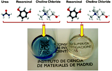 | ||
| Fig. 6 Picture shows the liquid aspect of the eutectic mixtures based on urea, resorcinol and choline chloride (left) and resorcinol and choline chloride (right). Adapted with permission from ref. 86 and 87. | ||
Carriazo et al. hypothesized that one of the components forming the DES (e.g., resorcinol) acts as a precursor of the polymer phase while the second component (e.g., ChCl) segregated into the polymer-depleted phase This mechanism actually resembles that described for DES-assisted synthesis of zeolites via ionothermal synthesis,102 except that DES rupture results from RF polycondensation rather than from thermal decomposition. The wide range of DESs that can be prepared provides a remarkable structural and compositional versatility to the carbons that can be obtained through this synthetic approach. For instance, one can control the dimensions of the macro and the micropore,98,99 and/or the composition (e.g., N- or P-doped),100,103 of the resulting carbon. Finally, carbon–CNT composites can also be obtained (Fig. 7).101 Thus, compared with conventional polycondensation processes used for the preparation of hierarchical carbons, the use of DESs offers a greener alternative by reducing or even eliminating the residues and/or by-products eventually released after the synthetic process. That is, one of the components forming the DES (e.g., resorcinol or mixtures of resorcinol with other precursors) becomes the material itself with high yields of conversion, whereas the second one (e.g., ChCl) is fully recovered and can be reused in subsequent reactions. Interestingly, DES-assisted polycondensation also preserved the green features observed in the original ones with respect to use of renewable feedstock, whilst future exploitation of sustainable resorcinol alternatives (e.g., biorefinery-derived phenolics) in material synthesis will further enhance the green credentials.
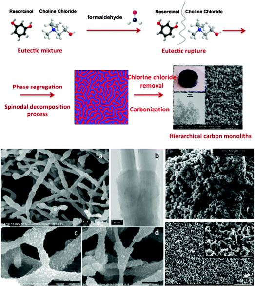 | ||
| Fig. 7 Top panel: scheme representing the formation of hierarchical carbon monoliths upon addition of formaldehyde to the eutectic mixture of resorcinol and ChCl, followed by eutectic rupture, phase segregation in a spinodal decomposition-like process, and carbonization. Bottom panel: SEM micrographs showing the hierarchical structure of carbon–CNT composites (a, c, and d), N-doped carbons (e), and P-doped carbons (f). TEM micrograph of carbon–CNT composites (b). Adapted with permission from ref. 86, 87, 98–101. | ||
3.2 Applications of porous carbon monoliths prepared from DESs
As mentioned above, DES-assisted syntheses provide both structural and compositional versatility that opens the path to the use of these porous carbons as supercapacitor electrodes and as substrates for CO2 capture and separation.![[thin space (1/6-em)]](https://www.rsc.org/images/entities/char_2009.gif) :
:![[thin space (1/6-em)]](https://www.rsc.org/images/entities/char_2009.gif) 1
1![[thin space (1/6-em)]](https://www.rsc.org/images/entities/char_2009.gif) :
:![[thin space (1/6-em)]](https://www.rsc.org/images/entities/char_2009.gif) 1 molar ratio was obtained. Polycondensation was carried out by the addition of formaldehyde and using phosphoric acid as a catalyst. Phosphorous-doped carbon monoliths were obtained upon the carbonization of the resulting RF resin while non-doped carbon monoliths were obtained when phosphoric acid was washed out of the phenolic resin prior to carbonization. The voltammograms of the P-doped carbon monoliths exhibited a rectangular shape that was maintained for remarkable voltages of ≥1.4 V (Fig. 8(a)). Actually, undoped carbons exhibited a clear deformation of the rectangular shape of the voltammogram at much lower voltages (e.g., 1 V) than the P-doped material. This widening of the operational-voltage-window was critical in achieving a significant enhancement in the energy density provided by the P-doped carbon monoliths.
1 molar ratio was obtained. Polycondensation was carried out by the addition of formaldehyde and using phosphoric acid as a catalyst. Phosphorous-doped carbon monoliths were obtained upon the carbonization of the resulting RF resin while non-doped carbon monoliths were obtained when phosphoric acid was washed out of the phenolic resin prior to carbonization. The voltammograms of the P-doped carbon monoliths exhibited a rectangular shape that was maintained for remarkable voltages of ≥1.4 V (Fig. 8(a)). Actually, undoped carbons exhibited a clear deformation of the rectangular shape of the voltammogram at much lower voltages (e.g., 1 V) than the P-doped material. This widening of the operational-voltage-window was critical in achieving a significant enhancement in the energy density provided by the P-doped carbon monoliths.
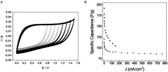 | ||
| Fig. 8 (a) Voltammograms of a P-doped carbon monolith recorded at 5 mV s−1 for voltages ranging up to 1.5 V. (b) Specific capacitance versus current density for a carbon–carbon nanotube monolithic composite (grey circles). For comparison, the same plot is represented for a monolith without MWCNT (black circles). Adapted with permission from ref. 101 and 103. | ||
It has been observed that the presence of graphitic carbon entities (e.g., CNTs,104 nanohorns,105 or even GO106) in such carbon monoliths may generate enhanced performance in terms of both mechanical properties and electrical conductivity. As discussed further, these carbon nanomaterials can be produced from sustainable resources. Thus, Gutiérrez et al. have described the preparation of MWCNT–carbon composites based on furfuryl alcohol (FA) and a protic DES – a complex of p-toluene sulfonic acid (pTsOH) and ChCl – as both the reaction medium and the protic catalyst promoting the polycondensation.101 The resulting carbons exhibited a bi-continuous porous network where a shell of FA-derived carbon coats the MWCNTs and forms strong junctions (Fig. 7(f)). The observed scaffold-like monolithic composite structure generates remarkable properties both in terms of electrical conductivity (≤4.8 S cm−1) and elastic character (Young modulus = 11 MPa). When these monoliths were used as supercapacitor electrodes, both features contributed to retain 75% of the initial capacitance at high current densities of 765 mA cm−2 (ca. 29 A g−1), well above the 55% at only 150 mA cm−2 found for bare porous carbon monoliths of similar dimensions (Fig. 8(b)). The rapid electrical response of the monolithic composites was also reflected in the power performance of the supercapacitor cell, with power densities of ca. 7.2 kW kg−1 at energy densities of 2.2 W h kg−1.
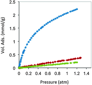 | ||
| Fig. 9 CO2 (blue), N2 (red) and CH4 (green) adsorption isotherms at 298 K of carbon monoliths prepared from resorcinol, 4-hexylresorcinol and tetraethylammonium bromide. Adapted with permission from ref. 100. | ||
3.3 Perspectives on DES-derived carbon materials
Summarizing, DESs offer a green alternative to conventional syntheses for carbon preparation. For instance, in terms of atom economy, DESs play an all-in-one role containing the precursor itself and some additional components that are either providing certain functionality to the resulting carbons or directing their formation with a particular structure (e.g., hierarchical-type). DESs also allow the co-condensation of different precursors, encompassing their kinetic reactions so that every precursor is finally distributed homogeneously throughout the final structure of the resulting carbon. These carbons with tailored composition and porosity are suitable as electrodes in supercapacitor cells as well as adsorbents for CO2 capture.Nonetheless, the challenge of DES-assisted polycondensations remains in producing mesoporous carbons and/or carbons with higher surface areas that will allow exploring new applications where these particular features are required. Obviously, the above-mentioned applications may also benefit from these features. Expanding the heteroatoms doped into the carbon network – to boron, for instance – and the percentage of heteroatom incorporated into the carbon network is also challenging. Within this context, the capability of DES-assisted syntheses to prepare carbons dually co-doped – with more than one heteroatom rather than with a single one – will have to be also explored in forthcoming works.
In addition, using natural DESs should further increase the green character of this methodology for the future production of carbon materials. Such DESs were found to serve some basic function in living cells and organisms and include sugars, some amino acids, choline, and organic acids such as malic acid, citric acid, lactic acid, and succinic acid.95
4. Starbons
4.1 Synthesis and background
Given their natural abundance and general low cost, coupled with a well-documented ability to form thermo-reversible aqueous gels, polysaccharides can be viewed as excellent precursors for the preparation of, firstly, porous polymer cryo-, xero- and aerogels,115 and if the useful porosity can be maintained into the final product, secondly as the precursor for porous carbon preparation. In their native form, polysaccharides typically have a low surface area and little developed porosity. The “expansion” of these compact (often semi-crystalline) polymers is therefore vital for the development of materials (e.g., sustainable porous carbons) that are suitable for applications where mass transport/diffusion (e.g., chromatography) and surface interactions (e.g., liquid phase catalysis) are critical to function. The work of Glenn et al. and Te Wierik et al.330 in the 1990s demonstrated the preparation of starch-based xerogels (SBET < 145 m2 g−1), based on a sol–gel-like process involving the thermal gelation and recrystallization (often to referred to as “retrogradation”) of starch, followed by the careful replacement of pore entrapped H2O for a lower surface tension solvent (e.g., CH3CH2OH) and eventually air (e.g., via supercritical extraction).116In more recent publications this approach has been generalized to “porous polysaccharides” that is in principle applicable to the majority of polysaccharides (Fig. 10).13 Gelatinisation temperature/heating mechanism (e.g., microwaves),118 polysaccharide type/structure,119 additive,120 and drying technique,121–123 have all been utilised to direct textural (e.g., micro- vs. meso- vs. macroporosity) and physicochemical properties (e.g., solid base vs. acid). The resulting porous polysaccharides are soft polymeric networks stabilised by dense hydrogen-bonding between chains and local domains. These inherent hydrophilic networks are metastable and unstable in the presence of protic reagents, limiting potential end applications. Therefore stabilisation of the porosity of these materials has been a crucial goal. Complimentary to other approaches discussed in this review, the transformation of porous polysaccharides to porous carbon represents an interesting alternative to extensively reported carbons prepared using soft or hard templating strategies (e.g., C-FDU-14,124 CMK-1,7etc.) or classical RF-derived carbons.125 This approach can also act to valorise otherwise low value polysaccharides, particularly when these polymers are sourced from wastes such as orange peel pectin.126
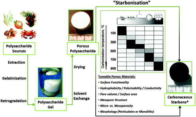 | ||
| Fig. 10 A generalised preparation of Starbons®, involving sourcing of the polysaccharide, followed by the preparation of an aqueous gel, its controlled drying and subsequent conversion to tuneable, functional porous carbonaceous materials – i.e., starch to carbon – Starbons®. Taken with permission from ref. 117. | ||
The first example of this approach, reported in 2006, demonstrated the conversion of mesoporous starch into carbonaceous derivatives, denoted under the trademark Starbons®.117 The general principles of the synthesis of 1st (starch-derived) and 2nd generation (alginic acid or pectin-derived) Starbons® has been discussed in previous reports.13,115,126,127 Briefly, highlighting recent insights, the synthesis involves introducing the acid catalyst p-toluene sulfonic acid to the surface of the neutral porous starch, followed by heating to the desired temperature under a non-oxidising atmosphere (normally > 150 °C) to induce cross-linking processes (e.g., dehydration) at temperatures lower than the melt of the hydrogen-bonded polymer network. In this manner 1st generation Starbons® are based on the acid-catalysed decomposition of organised nano-scale structure of helix-forming amylose (poly-α-(1→4)-D-glucopyranose). Success in extending this synthetic approach to other helix-forming polysaccharides such as alginic acid and pectin indicates the necessity of polysaccharide helicity or a degree of glycosidic bond flexibility to allow nanopore stabilisation and opens access to a wide range of mesoporous materials.126,128,129 In this context, the decomposition chemistry of acid-doped starch and alginic acid have been found to be very similar as demonstrated by Shuttleworth et al. via detailed diffuse reflectance IR spectroscopy in Fourier transform mode (DRIFT) (Fig. 11).130
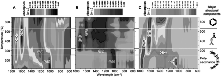 | ||
| Fig. 11 Composite DRIFT contour plot analysis for the decomposition of (A) Starbon® produced from acid-doped porous starch; (B) acid-free starch (non-porous); and (C) alginic acid; prepared as a function of carbonisation temperature. Reproduced with permission from ref. 130. | ||
Samples were prepared in the temperature range of 100–700 °C, with analysis demonstrating that at temperatures >300 °C the thermal decomposition of polysaccharides, independently of their functionality and the presence of an acid catalyst, leads to materials with similar functionality. This FTIR analysis indicated that external (acid-doped starch) and internal acidity (alginic acid) play a key role at temperatures between 180–300 °C in inducing intermolecular crosslinking/dehydration of hydroxyls to generate ethers (ν = 1209 cm−1) and carbonyls (e.g., carbon in sp2 hybridisation, ν = 1700 cm−1 at 200 °C). In contrast, native starch is thermally stable in this temperature range and hydroxyl groups predominate at ≥300 °C. The second major carbonisation event occurs in the 300–550 °C range. This event is relevant to all polysaccharides and is followed by further structural dehydration to induce the formation of C–C (olefinic) double bonds (ν = 1670 cm−1) conjugated with carbonyl groups. This is followed at Tp > 550 °C by the conversion of 1D linear conjugated groupings to 2D (surface plane) increasingly more condensed, aromatic structures (ν = 700–950 cm−1 (C–Haromatic)). The last carbonisation transition results in the formation of structures with increased long-range order and features increasingly more associated with classical carbons.
Shuttleworth et al. also observed for starch-derived Starbons® the formation of wormhole-like inter-pore connections after heating to 300 °C, within which micropores develop via entrapped decomposition product/gas evolution to initiate the formation of a predominantly sp2-carbon structure. Starch-derived Starbons® prepared at T < 300 °C presented minimal microporosity, being composed of interconnecting network structures, as opposed to large mesoporous domains provided from the original starch structure. Carbonisation at T > 300 °C led to domain interconnection and the production of wormhole-like mesopores in the carbon, features beneficial in certain applications (e.g., supercapacitors).131,132 This work is significant as it provides the basis for a general understanding of the carbonisation process of polysaccharides used in Starbon® synthesis and the relationship between chemical functionality, decomposition temperature, surface energy/hydrophobicity/polarisability and structure – an understanding that is essential for the future optimised design of porous carbonaceous materials for specific applications.
Whilst the decomposition chemistry may be of a general nature for acidic polysaccharides and the acid-doped neutral polysaccharides, the material porosity of Starbons® is very subtly effected by the choice of polysaccharide precursor – presumably related to phase separation behaviour (e.g., as a result of surface charge) and polysaccharide self-associations (e.g., helical domains). 1st generation Starbons® typically present higher micropore content as a function of Tp as compared to 2nd generation Starbons®, arising presumably from a difference in kinetics between a surface initiated/catalysed vs. a bulk decomposition process. Starbons® prepared from inherently anionic/acidic polysaccharides typically produce larger mesopore volumes (e.g., >0.8 cm3 g−1) and diameters (e.g., >10 nm). More subtle influences on material porosity relating to polysaccharides self-association and indeed charge – e.g., as double helical structures in the amylose homopolymer vs. the polyuronide block alginic acid copolymer (composed of (1→4)-linked-β-D-mannuronic acid (M), and α-L-guluronic acid (G) residues as homo- or heteropolymer segments),133,134 – are currently under investigation.
Apart from offering access to Starbons® of differing textural properties, the use of highly acidic polysaccharides (e.g., pKa of alginic acid = 3.0 and 3.8,135–137) is particularly advantageous from a process and final end use point of view. It eliminates process steps involving the introduction of the p-toluene sulfonic acid decomposition catalyst (and any other steps for its removal), allowing access to more functional lower temperature Starbons®. The presence of residual “S” may also be problematic if the Starbon® material is ultimately to be used as a support in catalysis where the active site is sensitive to poisoning. Starbon® preparation from alginic acid, pectin, chitosan and carrageenan (e.g., –OH, –C(O)OH, –NH2, –SO3H) is significant as it extend interest beyond “neutral” polysaccharides and offers scope for simpler production, heteroatom doping, decomposition chemistry control and direction of physicochemical (e.g., electrochemical, polarisability, etc.) properties. Interestingly, it may also be possible to eliminate the polysaccharide extraction step and use naturally occurring structures or forms (e.g., macroalgae138) to directly prepare useful Starbon® materials.
4.2 Applications
4.2.1.1 Chromatographic stationary phases. Historically, the use of “Porous Graphitised Carbons” (PGCs)139–141 as stationary phases in the separation of highly polar analytes has proven relatively successful (compared to reverse phase C18-silica based columns).142,143 The preparation of PGC involves the impregnation/nanocasting/replication of silica spheres (e.g., 5 μμm diameter) which is arguably expensive, resource/step intensive and wasteful, whilst carbonisation of the carbon precursor at high temperatures (>1400 °C) to eliminate non-desirable microporosity, does not provide scope to modify the surface chemistry of the phase to optimise surface polarity or functionality for a given separation challenge. In this context, the flexibility of the Starbon® approach can open scope for the synthesis of designer stationary phases, whereby surface polarity/functionality is controlled via selection of the carbonisation temperature. This approach would allow control of the degree of the graphitic structure development and in turn the degree to which the surface features delocalised “π” clouds. Exploiting this concept, White et al. prepared an alginic acid-derived stationary phase with very low micropore content and large mesopore volumes.127 The material was carbonised at 1000 °C and the resulting HPLC column was shown to be a very useful carbon stationary phase for the separation of representative highly polar neutral sugars, glucose (mono-), sucrose (di-), raffinose (tri-), stachyose (tetra-) and verbascose (pentasaccharide), with separation efficiencies marginally improved as compared to PGC under the same separation conditions.13
However, a shortcoming of this initial report relates to the lack of defined particle morphology, with overall particle size and morphology unfortunately not easily controlled. The original alginic acid-derived Starbon® phase presented a broad particle size range (∼1 to 100 μm) composed of spherical to rod-shaped particles, which could lead to reduced column packing efficiency, which in turn affects overall column flow characteristics, leading to peak broadening and reduction in peak resolution. To improve the regularity of alginic acid-derived Starbon® phases, Clark et al. have recently reported the synthesis of Ca-alginate-derived Starbons® (denoted as AMCS) with increased particle regularity, without sacrificing the promising pore structuring of the original alginic acid-derived phase (Fig. 12).144
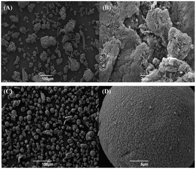 | ||
| Fig. 12 SEM images of alginic acid-derived mesoporous carbon (Starbon®) (A) ×250 and (B) ×6000 magnification and AMCS (C) ×250 and (D) ×5000 magnification. Both samples were prepared at a carbonisation temperature of 800 °C. Reproduced with permission from ref. 144. | ||
This approach relies on the classical “egg-box” interaction between the anionic polysaccharide structure and Ca2+,145 and electrospray ionization solution spraying to form spherical alginate precursors. The AMCS-derived Starbons® produced high quality spherical particles (i.e., 0.795 vs. 0.777 (PGC) vs. 0.594 (alginic acid-derived Starbon®) – based on mean particle circularity measurements), although the mean particle diameter was significantly larger than the PGC comparison (i.e., 23.4 vs. 7.0 μm). As an extension to the previously reported LC-MS separation of neutral polar sugar analytes,127 the separation of a sugar and sugar alcohol mixture (i.e., glucose, mannitol, sucrose, maltitol, raffinose, stachyose and verbascose) was attempted using columns (100 × 4.6 mm) packed with A800, and ACMS-800 °C, using a commercial PGC column for comparison (denoted as Starbon®-LC-MS, ACMS-LC-MS and PGC-LC-MS, respectively) (Fig. 13).144 The representative ESI for the seven investigated sugar and sugar alcohol analytes indicated a similar elution order for the three investigated stationary phases with maltitol eluting marginally earlier than sucrose, and raffinose, stachyose and verbascose co-eluting. The retention time spread for these five analytes was found to be marginally narrower for the Starbon®-LC-MS system (0.2 min) than for the other two systems (0.7 min), which could indicate a reduced resolving capability for this phase. Interestingly, the largest retention time variation over the three systems was observed for the glucose and mannitol with the AMCS-LC-MS system (4.9 min and 5.1 min, respectively) appearing to retain these analytes longer as a consequence of improved phase packing efficiency and the presence of strongly binding micropores in this phase.
 | ||
| Fig. 13 Extracted ion chromatograms (ESI) of 50 mg mL−1 standard solution of a mixture of glucose, mannitol, sucrose, maltitol, raffinose, stachyose and verbascose obtained for (A) AMCS-LC-MS and (B) Van Deemter curves for a 50 mg mL−1 sucrose standard solution eluting at various flow rates from the AMCS-LC-MS (■), Starbon®-LC-MS (●) and PGC-LC-MS (▲) systems. Adapted with permission from ref. 144. | ||
In order to quantitatively assess the efficiency of the three investigated separation systems, the corresponding Van Deemter (VD) curves were constructed based on the retention time and peak width at half maximum values for a standard 50 mg mL−1 solution of sucrose standard eluting under isocratic conditions at various flow rates (Fig. 13(B)). VD plots for Starbon®-LC-MS commence at larger plate height values compared to the other two systems, indicative of a greater eddy diffusion contribution to peak broadening, with the authors suggesting this may be the result of a wide particle size distribution and poor particle shape limiting packing efficiency. Interestingly, at low flow rates, the AMCS-LC-MS system plate height value resembled closely that of PGC-LC-MS demonstrating that the packing efficiency is markedly improved as a result of the improvement of the Starbon® particle sphericity.
In a complimentary report, Brydson et al. have examined the differences in microstructure and bonding of these two alginic acid-derived stationary phases and commercial PGC.146 A combination of HRTEM, electron energy loss spectroscopy (EELS), N2 porosimetry and XPS described the relative differences between the three phases, demonstrating that the planar carbon sp2-content of all three materials was similar to that of traditional non-graphitising carbons, although both alginic acid-derived materials presented a larger percentage of fullerene character (i.e., curved graphene sheets) than a non-graphitizing carbon pyrolysed at the same temperature. HRTEM images demonstrate that the alginic acid-derived Starbon-800 °C (A800) are less ordered than the commercial PGC phase, presenting only minimal ordering of (002) graphitic planes, (ca. 2–3 aligned layers) (Fig. 14(a)–(d)).
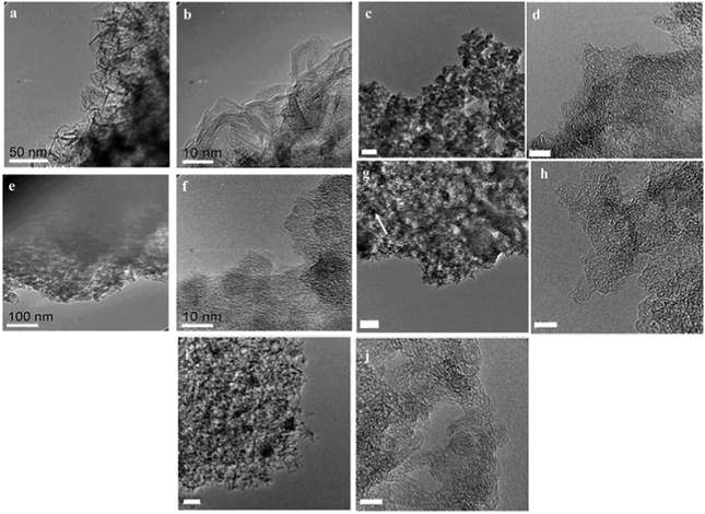 | ||
| Fig. 14 High resolution TEM images of commercial PGC at (a) low and (b) high magnification; alginic acid-derived Starbon® prepared at 800 °C (A800) at (c) low (scale bar = 50 nm) and (d) high magnification (scale bar = 5 nm); A1000 (e) low and (f) high magnification; and AMCS-NW (g) low (scale bar = 50 nm) and (h) high magnification (scale bar = 5 nm) and AMCS-W (i) low (scale bar = 50 nm) and (j) high magnification (scale bar = 5 nm). Reproduced with permission from ref. 146. | ||
For A1000, low magnification images indicate the same microparticles and pore structuring as observed in A800 (Fig. 14(e)). Increasing magnification revealed that the fullerene-like character and loop structuring is more pronounced, with an increase in graphitic layer thickness (ca. 3–5 layers of graphene), which resembles typical non-graphitizing carbon (Fig. 14(f)). AMCS prepared at 800 °C showed extensive fullerene-like character (Fig. 14(g) and (h)). The addition of Ca2+ to the alginic acid precursor leads, after carbonisation at 800 °C, to a Starbon® with a high degree of smooth curvature and a more open porous network. This sample was washed free of calcium to reveal slightly thicker stacking layers (4–5 graphene layers) (Fig. 14(i) and (j)). A comparison of A800 and A1000 with AMCS demonstrates that the addition of Ca2+ to the synthesis has a dramatic impact on the overall material morphology. Whilst A800 and A1000 are composed of agglomerated particulates, AMCS-derived samples present a morphology which is more akin to an expanded carbon-based material, with a more open mesoporous structure (Fig. 14(g)). This work highlights the impact of altering the polysaccharide conformation in the gel phase and demonstrates the significant differences between the microstructures of the commercial PGC, alginic acid- and AMCS-derived Starbons®. These observed nanostructural differences, in tandem with XPS analysis, were proposed to be the result of Ca2+-catalysed fullerene structure formation. The A800 and ACMS phase have extensive graphitic layer curvature due to the high-fullerene character whilst the microstructure of PGC predominantly features extended planar graphitic stacks. Brydson et al. comment that even though chromatographic properties of the three phases are similar, that at the molecular level, retention on fullerene-like and turbostratic graphite sites for an analyte is essentially equivalent, whilst the development of graphitic stacking with a layer number >6 has a minimal effect on retention behaviour. Whilst both the reported alginic acid-based Starbon® phases show excellent promise in analytical chromatography, particularly as green (and possibly less costly) replacements for PGC, further research is needed to optimise/reduce particle size and improve mesopore structure/ordering (to improve mass transfer at higher flow rates) to enable these materials to realise their full potential.
4.2.1.2 Reversible sorbents in waste water purification. The use of ACs as a physical adsorption matrix is well known and considerable attention has focused on their use in a range of water purification applications including the adsorption of phenolic and dye pollutants (e.g., azo-dyes).148–150 As discussed briefly above, predominantly microporous ACs are typically derived from a wide variety of biomass (e.g., rice husks, coconut shells, etc.151,152) that whilst effective in adsorption applications, can be inaccessible in terms of price or availability, and from a materials standpoint the limitation of extensive microporosity results in the need for large volumes to enhance extraction rates. Hunt et al. have recently exploited the starch- and alginic acid-derived Starbon® materials in the removal of dyes (i.e., methylene blue (MB) and acid blue (AB) 92),147 and recovery of phenols153 from aqueous solutions. With regard to the adsorption of MB and AB from waste water, mesoporous Starbon® materials were prepared at carbonisation temperatures of 300 and 800 °C (i.e., S300, S800, A300 and A800) (Table 1). Starbon® adsorbents were evaluated against commercial AC (Norit) and it was found that A300 presented a larger adsorption capacity of MB (i.e., 186 mg g−1vs. 42 mg g−1). The kinetic activity analysis also demonstrated that A800 had the fastest rate of adsorption as compared to S800 and Norit, suggesting that it is a more suitable material for water purification. This work demonstrated highly efficient dye adsorption from wastewater using Starbon® adsorbents, and the important inter-relationship between mesoporosity, surface functionality and efficient adsorption behaviour. The significance of this finding is that it contradicts conventional theory, with the presented results suggesting that a large surface area is not absolutely necessary for high adsorption capacities and that large pore volume and diameters are principally important for efficient dye uptake. In particular, A300 and A800 adsorbents with very high mesoporosity outperform the commercial, high surface area Norit in both adsorption capacity (four times greater for MB) and speed of adsorbate uptake.
| Adsorbent | Methylene blue | Acid blue 92 | ||
|---|---|---|---|---|
| Adsorbent capacity (mg g−1) | Surface area (m2 g−1) | Adsorbent capacity (mg g−1) | Surface area (m2 g−1) | |
| S300 | 36 | 72 | 27 | 41 |
| S800 | 52 | 104 | 39 | 59 |
| A300 | 186 | 373 | 82 | 124 |
| A800 | 97 | 195 | 108 | 164 |
| Norit | 42 | 83 | 49 | 74 |
The use of S800 and A800 for the adsorption and desorption of polar aromatic compounds from aqueous solution has also been successfully demonstrated (Fig. 15). Adsorption capacities were found in range between 87–139 mg g−1, comparable or better than other bio-based adsorbents. Extensive isotherm analysis based on the Langmuir, Freundlich, and Dubinin–Radushkevich (DR) models, revealed that adsorption was multilayer for both S800 and A800 – typical of such mesoporous sorbents. Derivation of the mean adsorption energy using the DR model demonstrated that all the investigated phenols were adsorbed via physisorption mechanisms, with adsorption by A800 found to be strongly dependent on the substituent group on the phenol ring, with monolayer adsorption capacity increasing as the electron-withdrawing effect of the phenol substituent increased – contrary to behaviour observed for the S800 sorbent.
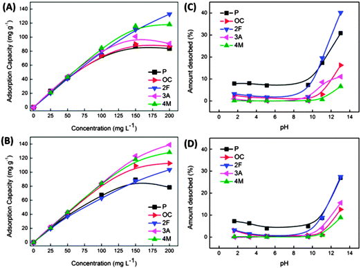 | ||
| Fig. 15 Equilibrium adsorption capacities obtained at different initial phenolic concentrations and corresponding desorption behaviour (by varying pH) S800 (A and C) and A800 (B and D) Starbon® sorbents. Adsorbates: phenol (P), o-cresol (OC), 2-fluorophenol (2F), 3-aminophenol (3A), and 4-methoxyphenol (4M). Reproduced with permission from ref. 153. | ||
This observation coupled with the associated thermodynamic parameters suggests adsorption occurs via different mechanisms for S800 and A800 as a product of the larger micropore content of S800 as compared to the higher mesoporosity and enhanced degree of surface aromatization for A800 (i.e., 28 vs. 45% (from XPS analysis)). Importantly in terms of sorbent recycling and recovery of the phenolic compounds, desorption of adsorbed compounds could also be achieved, resulting in 7 to 40% mass recovery (depending on the substituent on the phenol ring) (Fig. 15(C) and (D)) by exposing the sorbents to basic solutions with a pH > 11 with the highest removal achieved for S800. This work is significant as it lays the basis for the development of reversible sorbent technology based on a tuneable, green and accessible Starbon® materials platform.
4.2.2.1 Platform chemical conversion – hydrogenation. The hydrogenation of biorefinery platform chemicals (e.g., succinic acid (SA)) is of serious interest if this new refinery concept is to satisfy our future chemical production needs. Luque et al. have reported on the hydrogenation of SA under mild reaction conditions (i.e., 10 bar H2, 100 °C) in aqueous ethanol.156 In this initial communication, starch-derived Starbon®-300 °C (S300) was used as the functional carbonaceous support for Pt, Pd, Rh, and Ru nanoparticles (5 wt% loading). This Starbon® was selected as a support due to its highly heterogeneous (e.g., oxygenated) functionality and stability under aqueous conditions. Ru–S300 and Pt–S300 were found to present the highest conversion, with aberration-corrected high angle annular dark field STEM (AC-HAADF-STEM) analysis suggesting high activity was a consequence of these noble metal NPs being of a smaller diameter and more evenly dispersed as compared to the other investigated materials (Fig. 16(a)–(d)). Selectivity was different for Ru–S300 (i.e., hydrogenation to tetrahydrofuran – 60–82%) as compared to Pd, Pt, and Rh–S300 materials, demonstrated by a greater selectivity to 1,4-butanediol. Significantly, the reaction conditions could be selected to maximize γ-butyrolactone production from Pd–S300 or Ru–S300 (e.g., ≥65% selectivity at 45% conversion/10 h/5% Pd–S300). Importantly, the reported S300-supported catalysts were shown to maintain >95% of their initial activity after five reaction cycles. Using Ru–S300, the hydrogenation of itaconic acid in aqueous/ethanolic solution (100 °C; 1 MPa H2; 5 wt% Ru) was found to afford a 95% yield of 2-methylsuccinic acid.157
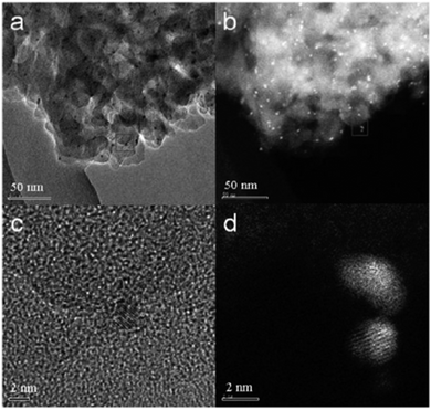 | ||
| Fig. 16 (a) AC-TEM and (b) AC-HAADF-STEM images of the 5% Ru–S300 catalyst. (c) and (d) are high-resolution AC-TEM and AC-HAADF-STEM images corresponding to the areas marked by squares in (a) and (b), respectively; reproduced with permission from ref. 156. | ||
The application of Starbon®/noble metal catalysts has recently been extended to the hydrogenation of levulinic acid (LA) to 2-methyltetrahydrofuran (MTHF) – a potential biofuel or green solvent – under microwave irradiation (MW).158 The authors reported on a different hydrogenation pathway compared to Cu-based catalysis for S300-supported catalysts (e.g., Pd, Ru, Rh). The formation of γ-valerolactone (GVL) was observed (e.g., when catalysed by Ru–S300) and was proposed to be the key intermediate in the hydrogenation scheme via three competitive processes (Fig. 17(A)). Angelica lactone (AL) was produced (as observed for S300-based catalysts) and subsequently hydrogenated to GVL.
 | ||
| Fig. 17 (A) Proposed reaction pathways for levulinic acid conversion to a variety of important compounds based on the use of noble metal catalytic systems [key steps (bold arrows)] and the favoured/promoted catalysed chemistries; (B) S300 supported Pd nanoparticles (5 wt% loading). Adapted with permission from ref. 158. | ||
Luque et al. report that GVL is also favoured via hydrogenation of the LA carbonyl group at the 4-position to yield 4-hydroxyvaleric acid (HVA) on noble metal sites, with in situ generated hydrogen from formic acid decomposition, followed by dehydration/cyclisation to GVL. The lactone intermediate can then be hydrogenated to either pentanoic acid or 1,4-pentanediol (PDO), with a short batch reaction favouring PDO (and then MTHF via dehydration), with PA forming in increasing quantity at longer reaction times under flow conditions. TEM images of S300-supported noble metal catalysts (e.g., Pd–S300; Fig. 17(B)) indicated very finely dispersed small (<9 nm) metallic NPs within the mesoporous carbonaceous support.
4.2.2.2 Platform chemical conversion – esterification. As a follow up to the initial work of Clark et al. regarding the use of Starbon®–SO3H catalysts in the aqueous phase esterification of succinic acid, Du et al.159 applied these solid acids in fresh and sea water “biorefineries”. The catalyst employed in these studies was the S400–SO3H (loading of ca. 0.5 mmol g−1), for the esterification and amidation of SA under saline or fresh conditions. S400–SO3H was tested in the esterification of a SA-enriched seawater-pure fermentation broth (FB) as compared to pure SA crystals, FB recovered SA crystals and a SA enriched plain water FB (Fig. 18). Reaction rates were significantly slower compared to reactions performed with pure or recovered SA crystals and only high conversions with relevant selectivities to the diester (diethyl succinate, (DIES)) were observed after 12 h. The replacement of ethanol for methanol in the esterification reaction improved the rate, provided high conversions and selectivities to DIES (close to 70%) after 4 h. However, whilst the catalyst maintained satisfactory activity, the reported results were still far from the quantitative conversion and selectivity to DIES observed for pure or recovered SA crystals.
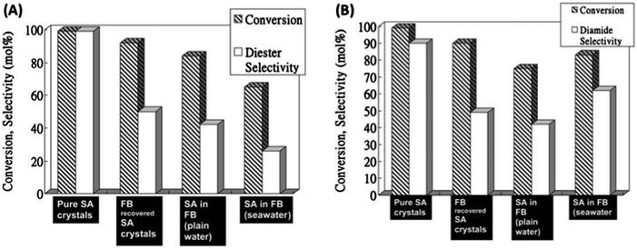 | ||
| Fig. 18 (A) Esterification reactions of succinic acid (SA) with ethanol using: pure SA crystals, FB recovered SA crystals, SA-enriched plain water FB (pH = 4) and SA-enriched FB using seawater; reaction conditions: 1 mmol SA (3 mL FB), 30 mmol EtOH, 50 mmol H2O (no water added in the case of FB experiments), 0.1 g S400–SO3H, 80 °C, and 4 h; (B) amidation of SA with benzylamine using pure SA crystals, FB recovered SA crystals, SA-enriched plain water FB (pH = 4), and SA-enriched seawater FB. Reaction conditions: 1 mmol SA (3 mL FB), 2 mL benzylamine, 0.1 g S400–SO3H, 120 °C, and 8 h. Adapted with permission from ref. 159. | ||
4.2.2.3 Biofuel synthesis. Starbon®-based catalysts have been employed in the production of biodiesel-like fuels (i.e., fatty acid methyl esters (FAMEs)) (Fig. 19).160 Waste oils containing high free fatty acid (FFA) concentrations were converted to biodiesel-like fuels employing S400–SO3H under both conventional and microwave heating. The Starbon® acids were found to be active in the esterification of FFA with methanol and also triglyceride (TG) transesterification found in the waste oil to yield biodiesel and glycerol. S400–SO3H (loading = 0.4 mmol g−1) was active for the production of biodiesel from waste oil with high FFA content (>10 wt%), with conversion to FAMEs reported to be >95 mol% (e.g., reaction time = 15 h, T = 80 °C, rapeseed waste frying oil containing 10 wt% FFA). The reaction followed a simultaneous FFA esterification and TG trans-esterification pathway, demonstrating recyclability and higher activity as compared to similar materials (i.e., DARCO-G60–SO3H and Silica–SO3H) and commercial solid acids (e.g., Amberlyst – 70% FAME conversion; Beta25 zeolite – 25% FAME conversion) (Fig. 19(B)). Reactions rates could be increased by employing MW, reducing reaction times from ≥12 h (using conventional heating) to <45 min, without a reduction in activity. The Starbon®-based catalyst maintained high FAME conversions after five recycle runs (>70 mol%), with the use of MW heating proving to be beneficial in terms of prolonging the high activity of the catalyst over a high number of catalytic runs (Fig. 19(C)).
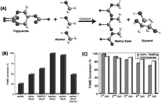 | ||
| Fig. 19 (A) Transesterification of triglycerides to produce fatty acid methyl esters (FAME biodiesel); (B) activity comparison of different solid acids in the production of FAMES from waste oils under optimized reaction conditions; and (C) a comparison of subsequent uses of Starbon® acid in the trans-esterification of rapeseed waste frying oil under conventional heating and MW. Reaction conditions – conventional heating: waste oil (1 mL), methanol (3 mL), starbon acid (0.1 g), T = 80 °C, t = 12 h; MW: waste oil (1 mL), methanol (3 mL), S400–SO3H (0.1 g), 300 W, Tmax = 108 °C/Taverage = 83 °C, t = 30 min. Adapted with permission from ref. 160. | ||
4.2.2.4 Alkylation and acetylation reactions. Recently, Luque et al. reported the synthesis of various Starbon®-supported acids (i.e., Starbon®–SO3H, Starbon®–C(O)OH, ZnCl2–Starbon® and BF3–Starbon®), which were used in the acetylation of 5-acetyl-methylsalicylate and the alkylation of phenol with cyclohexene (Table 2).161
| Catalyst | Brønsted/Lewis ratiob | Time (h) | Conv. (mol%) | Selectivity (mol%) | ||
|---|---|---|---|---|---|---|
| O-alkylation | (o-) C-alkylation | (p-) C-alkylation | ||||
| a Reaction conditions: 1 mmol phenol, 2 mmol cyclohexene, 3 mL toluene, 0.2 g catalyst, 110 °C. b Brønsted/Lewis ratio of the different investigated catalysts [obtained from pyridine-DRIFT spectra dividing areas under Brønsted (1540 cm−1) and Lewis (1440 cm−1) bands]. | ||||||
| Blank | — | 24 | — | — | — | — |
| S500–SO3H | 0.80 | 1 | 35 | 74 | 21 | 5 |
| 4 | 60 | 71 | 24 | 5 | ||
| 8 | 75 | 68 | 27 | 5 | ||
| 12 | 95 | 65 | 30 | 5 | ||
| S300–C(O)OH | 1.6 | 4 | — | — | — | — |
| 8 | <10 | >90 | Traces | <10 | ||
| 22 | 25 | >90 | Traces | <10 | ||
| 48 | 85 | 78 | 5 | 17 | ||
| 10 wt%-ZnCl2–S300 | 0.31 | 4 | <15 | 82 | 15 | 3 |
| 8 | 39 | 80 | 15 | 5 | ||
| 22 | 60 | 60 | 27 | 13 | ||
| 48 | >99 | 68 | 22 | 10 | ||
| 10 wt%-BF3–S300 | 0.43 | 8 | 18 | >90 | <5 | <5 |
| 22 | 31 | >90 | <5 | <5 | ||
| 48 | >95 | 80 | 16 | 4 | ||
| FeCl3–clay | 0.08 | 8 | — | — | — | — |
| 22 | <15 | >90 | <5 | <5 | ||
| 48 | 35 | 79 | 9 | 12 | ||
| Sulfated-ZrO2 | 1.05 | 8 | 28 | 17 | 15 | 68 |
| 22 | 55 | 30 | 19 | 51 | ||
| 48 | >99 | 13 | 27 | 60 | ||
| Beta25 Zeolite | 0.75 | 1 | 47 | 18 | 22 | 60 |
| 4 | 73 | 15 | 20 | 65 | ||
| 8 | >99 | 14 | 18 | 58 | ||
Of the investigated catalysts, S500®–SO3H was found to be the most active for alkylation of phenol with cyclohexene, affording a quantitative conversion after 10 h, with activity quite similar (based on conversions) to the strongly acidic Beta25 zeolite (Table 2). Luque et al. reported that S300-supported Lewis acids (e.g., BF3–S300) were less active than Starbon–SO3H, beta zeolite and sulfated zirconia. The low activity of S300–C(O)OH, despite its high Brønsted acidity, was proposed to be the result of strong phenol adsorption (via H-bonding) at acid sites, leading to partial deactivation. Of the possible alkylation products, O-alkylation (to yield cyclohexyl phenyl ether) was favoured for all catalysts (selectivities ranging from 70 to 95%). Significantly, starbon acids were found to be highly active and selective in both the test reactions, preserving their activities after four reuses. These materials were also found to be more active and selective to the target products as compared to other solid acids (i.e., sulfated zirconia, clay supported Lewis acids and zeolites), whilst further optimisation of surface chemistry for higher activity or alteration of selectivity is still possible, given the flexibility of the Starbon® synthesis.
4.2.2.5 Photocatalysis. The interest and potential of Starbon® materials in general and specifically in catalysis has resulted in the production of a raft of patents and an associated spin-off company “Starbon® Technologies Ltd.”.163 Sigma-Aldrich has a license to distribute S300 and S800 materials and are available for purchase via their internet site.164 This provides the opportunity for other researchers to utilise these materials in applications perhaps not initially envisioned during material development. A recent example in this context, describes the development of Starbon®-supported TiO2 NP photocatalysts.162 TiO2 NPs of average particle size of ca. 30 nm were supported on S800. The resulting material was found to be a highly promising photocatalysts for aqueous phase total mineralization of phenol.
TiO2/S800 was found to have improved activity compared TiO2/Norit and TiO2/GO. The resulting activity of the Starbon®-based photocatalyst was proposed to be the result of reversible phenol adsorption on the hydrophobic S800 support and the highly dispersed TiO2, anchored to the mesoporous support via an ultrasound-induced impregnation method (Fig. 20). Colmenares et al. suggest the enhanced activity may also be due to a pure, highly crystalline anatase phase leading to a reduction in the electron–hole recombination rate at the Starbon® surface. TiO2 NPs are strongly anchored and have good contact to the S800 structure (i.e., no leaching after 240 min of photocatalysis), believed to enhance the photo-electron conversion (i.e., as compared Norit and GO supports) of TiO2 by reducing the recombination of photo-generated electron–hole pairs. This report is significant as it highlights that the potential of semiconductor/Starbon® composites in photochemical application, the activity/properties of which (e.g., charge transfer properties) may in principle be modulated (e.g., via selection of Starbon® preparation temperature), leading ultimately to designer novel hybrid mesoporous photocatalysts.
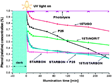 | ||
| Fig. 20 Photocatalyst activities in the aqueous phase degradation of phenol (reaction conditions: 150 mL of mother solution, 150 mg of photocatalyst, Cphenol = 50 ppm, temperature = 30 °C, pressure = 1 bar). P25 = commercial TiO2; Ti/GO = TiO2/graphene oxide; Ti/Norit = TiO2 supported on commercial carbon, Norit; Ti/Starbon® = TiO2 supported on S800. Reproduced with permission from ref. 162. | ||
4.3 Perspectives on Starbon®
In summary, Starbon® technology provides a useful and sustainable route to highly mesoporous carbonaceous materials with tuneable surface chemistry properties, arguably a material feature not accessible via conventional hard or soft template routes. By selection of gelation conditions, polysaccharide type and carbonisation temperature, a wide range of carbonaceous materials may be synthesised using inexpensive and readily available renewable sugar-based precursors. It is very significant that Starbon® technology could be easily synthesised from polysaccharides derived from different food waste such as pastry waste (source of starch), orange peel (source of pectin) and seaweed (source of alginic acid). The flexibility of the starbon technology combined with the stability and tunability of obtained materials makes them ideal candidates for application in future aqueous biorefinery chemistry, where they may be employed as both the heterogeneous catalyst support, and product separation media – a potentially elegant synergistic outcome for tomorrow's sustainable society. To develop these applications, a number of challenges have to be tackled such as reduction of solvent usage during Starbon® preparation as well as improving the electrical conductivity and mechanical stability of the Starbon® monoliths. There are a number of opportunities to solve these problems and further research in this regard is currently ongoing.5. Hydrothermal carbons
5.1 State of art
The first experiments on hydrothermal carbonisation (HTC) were performed by Nobel laureate, Friedrich Bergius as early as 1911, as a consequence of interest in producing H2via coal oxidation (and inhibit CO formation) using the “Water Gas Shift Reaction” according to the formula C + 2H2O = CO2 + 2H2.165 Working at temperatures <600 °C, (where steam has practically no effect on coal), Bergius managed to oxidize coal with liquid water at 200 bars yielding CO and H2, a reaction catalysed by transitional metals. Concurrently Bergius observed that when peat was used as the carbon source in this reaction, exceptionally large amounts of CO formed, and that the carbonaceous residue remaining in the vessel had the same elemental composition of natural coal. Further investigations by Bergius suggested that the plant biomass decomposition was very similar to natural coalification processes that occur over millions of years. Preventing super-heating of the system reduced the propensity for cellulosics to decompose and the resulting “carbonised” products have a very similar composition to natural coal.166 Bergius discovered that the biomass precursor required intimate contact with liquid water, which, at those mild temperatures (200 °C) in the high-pressure vessel, could not decompose into gases and instead formed “humins” or “hydrothermal carbon”.166,167 Bergius and his assistant Hugo Specht followed up this work,168 with their experiments leading to the production of liquid and soluble compounds from coal – the “coal liquefaction” process169 – and the award of the Nobel prize to Bergius in 1931.170 Following on from this seminal work, a number of researchers have investigated this process in the context of coal formation.171 In 1932, Berl and Schmidt varied the biomass source and treated the different samples in the presence of water at temperatures between 150 and 350 °C, contributing heavily to the understanding of coal structure at this time.172,173 Later, Schuhmacher et al. analysed the influence of pH on the outcome of the reaction and found serious differences in the decomposition schemes, as identified by the C–H–O composition.174,175Whilst somewhat forgotten during the course of the 20th century, a relatively recent renaissance of interest in this “synthetic coalfication” has occurred, starting with reports on the low temperature hydrothermal synthesis of carbon spheres (∼200 °C) derived from sugars such as glucose 2001.176,177 The addition of metal cations to the recipe was also found to accelerate the HTC of starch, shortening reaction times to several hours, resulting in the synthesis of various metal–carbon nanoarchitectures, including Ag@carbon nanocables,178 CNFs,179 and spheres.171 The Yu group (Hefei, China) is continuing great and valuable research on this topic.14 Following on from these initial works, the Titirici group has since focused efforts on demonstrating the potential of HTC-derived materials as sustainable alternatives to traditional carbons for renewable energy and environmental applications as published recently in a book with Wiley.180 Significant contributions to this topic have also been made by the Sevilla and Fuertes groups (e.g., mechanism, applications in gas storage; Ovideo, Spain),181–183 and the Berge group at the University of South Carolina (e.g., conversion of municipal waste into valuable carbon materials).184,185
Whilst a basic chemical understanding is critical to the development of these materials, research efforts focussed on fundamental engineering aspects and process parameters are also worth noting.186–192 Several spin-off companies and small-to-medium sized enterprises have taken an interest in large scale HTC production, as the resulting carbon chars have coal-like properties and are expected to exhibit favourable combustion and gasification behaviour (e.g., for decentralized applications), whilst the energy content of HTC chars has been measured as 25 to 35 MJ kg−1 – ca. 40% higher than that of the staring biomass precursor.193
5.2 HTC chemical structure
Whilst many characterisation studies have been performed, solid-state NMR (ssNMR) spectroscopy coupled with cross polarization (CP) and magic angle spinning (MAS) techniques has provided extremely useful and detailed insights into the complex chemical structure of HTC materials. Elemental analysis of typical HTC materials indicates the carbonaceous nature (>60 wt% C), FT-IR and XPS provides surface “functionality” information (e.g., C–OH, C![[double bond, length as m-dash]](https://www.rsc.org/images/entities/char_e001.gif) O, etc.) and XRD indicates that materials are typically amorphous after the hydrothermal synthesis. However, it is advanced 13C ssNMR techniques that can provide the most detail of HTC carbon chemical structure. However, as the finer details regarding the characterisation of HTC materials by NMR are published elsewhere,194,329 a brief overview of the main observations will provided in this review.
O, etc.) and XRD indicates that materials are typically amorphous after the hydrothermal synthesis. However, it is advanced 13C ssNMR techniques that can provide the most detail of HTC carbon chemical structure. However, as the finer details regarding the characterisation of HTC materials by NMR are published elsewhere,194,329 a brief overview of the main observations will provided in this review.
A typical 13C-MAS-CP spectrum of a glucose-derived HTC prepared at 180 °C presents three main regions: I – the aliphatic region (0–80 ppm); II – the aromatic region characteristic of sp2 hybridised carbons, where oxygen-bound sp2 carbons are detected ((100–160 ppm); and III – functionality typical of carbonyls, such as carboxylic acids, ketones, aldehydes, esters (175–225 ppm; Fig. 21(a)). Further details can be obtained using NMR pulse techniques such as Inverse Recovery Cross Polarisation (IRCP)195 making the discrimination of CH, CH2 and CH3 carbons possible in region I. INEPT (Insensitive Nuclei Enhanced by Proton Transfer),196 enables visualisation of carbon atoms directly having a chemical bond with hydrogen. 2D 13C homonuclear DQ–SQ (double quantum–single quantum) mapping enables the main structural units and the major bonding patterns of a carbonaceous framework structure to be deduced and allows identification of the structural motifs (e.g., Fig. 21(b))).
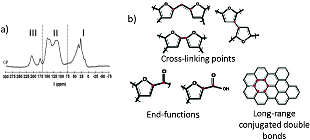 | ||
| Fig. 21 HTC chemical structure using 13C solid state NMR studies: (a) 13C-MAS-CP-NMR spectra of HTC-derived glucose at 180 °C; (b) structural motifs derived from 2D DQ–SQ 13C–13C correlation spectrum (from ref. 194). | ||
It is interesting to note that when synthesis is based on a pentose such as xylose, the final HTC structure is slightly different as a result of a synthetic pathway based on furfural and not 5-HMF (as hexoses), resulting in a “slightly more aromatic” structure due to lack of extra oxygen incorporation.197 These results are in good agreement with recent studies performed by Weckhuysen et al. A study on the HTC molecular structure using elemental analysis, IR, solid state 13C NMR spectra and pyrolysis-GC-MS revealed, in good agreement with our observations, a furanic structure with alcohol, acid, ketone and aldehyde functional groups, which is formed via a dehydration pathway. Based on this information a model for the molecular structure for glucose-derived humins was proposed. It was also found that xylose-derived humins have a more conjugated molecular structure.198
However, hexose-based cellulose makes the exception to this rule and the chemical structure of cellulose-derived material deserves special attention (Fig. 22). 13C CPMAS NMR spectra of cellulose-derived material produced at 180 °C presents similar resonances to pure cellulose, suggesting that there is a degree of resistance to the hydrolysis/dehydration process at this synthesis temperature. Increasing the synthesis temperature to ∼200 °C results in the formation of a product with resonances characteristic of hexose-derived HTC materials (aliphatic, aromatic and functional groups). However, a strong difference in the aromatic region (i.e., 120–130 ppm) can be observed. This peak is not observed for pure glucose-based HTC prepared at <200 °C. At higher temperatures, the spectra of hexose-derived HTC and cellulose-derived HTC are very similar suggesting a difference in the reaction mechanism. Further analysis reveals that the transformation of cellulose into HTC material in the absence of any catalyst does not occur below 200 °C via HMF as in the case of hexose precursors.199 Instead, the major conversion mechanism is more similar to “classical” pyrolysis where the cellulosic substrate is directly converted into the final carbonaceous material composed of an aromatic “arene”-like network. For cellulose-derived HTC material, Berge et al. discovered that using the ratio between the furan/arene resonances in 13C ssNMR, it is possible to isolate furan-rich intermediates at short reaction times (generally < 5 h depending on reaction temperature) and slow heating rates.200
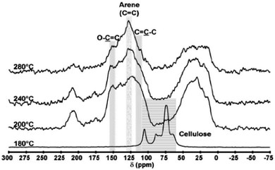 | ||
| Fig. 22 13C CP MAS NMR spectra recorded on HTC obtained from cellulose and prepared as a function of temperature. Reproduced with permission from ref. 199. | ||
One of the most important features of a general HTC synthesis (and indeed the aforementioned Starbon® synthesis) is that its chemical structure and surface chemistry can be directed using a secondary (post-synthesis) thermal carbonisation step. 13C CP MAS NMR spectroscopy of a glucose-derived HTC thermally carbonised at 350 °C demonstrates the high level of arene groups. This is supported by an increased intensity of the central resonance at δ = 125–129 ppm and a partial loss of the furanic shoulder at δ = 110–118 ppm, as compared to the parent HTC material. Increasing the temperature from 350 to 550 °C, the complete disappearance of the peaks corresponding to aliphatic and other functional groups (e.g., carbonyls, alcohols) is observed as well as of the furanic shoulder. Increasing the temperature to 750 °C leads to extensive material aromatisation, as indicated by broadening and drifting of the central aromatic resonance to a lower chemical shift (δ = 125 ppm), indicative of an extended delocalized π-system and of a reduced mobility of the carbon species.
It is also interesting to compare the structural differences between thermally pyrolised carbohydrate-derived carbons and hydrothermally carbonized examples (i.e., by 2D DQ–SQ 13C NMR experiments).201 Directly pyrolysed material does not present the shoulder at the δ = 118–110 ppm that is indicative of furanic units. Resonances in the δ = 148–151 ppm region (which are present in both examples) are attributed to aromatic carbons of oxygen-substituted arene-type moieties. The comparison of carbonaceous materials obtained from pyrolysis and glucose HTC strongly highlights that hydrothermal treatment offers an intermediate “material” stage between the features of the parent sugar and the polyaromatic char structure obtained via the direct pyrolysis route. These studies are in good agreement with results reported by Cao et al. in which two types of swine-manure chars, hydrothermally produced hydrochar and slow-pyrolysis char, and raw swine-manure solid were compared.202 The differences occurring in the resulting HTC chemical structure upon washing the product only with water or acetone was also investigated. Acetone extracted soluble intermediates deposited on the hydrochar, as shown by a decrease in O-alkyl features, corresponding to a relative increase in aromatic/olefinic carbon resonances and complete removal of OCH3 groups. This is in good agreement with Soxhlet extracted HTC samples, which demonstrated significant amount of levulinic acid can be extracted from glucose-derived HTC.203 Clearly the chemical structure of HTC material and thermally carbonised derivatives is very complex and the full mechanistic discussion and material characterisation represents a significant challenge. In this regard, future work using in situ monitoring and chemical isotope labelling techniques will provide further insights.
5.3 Nanostructuring and functionalisation
One of the main drawbacks of HTC materials produced directly from either carbohydrates or biomass is their lack of intrinsic porosity. However, performing a post-synthesis thermal carbonisation step (>350 °C) results in the development of very narrow diameter porosity and increase in the specific surface area (e.g., at 750 °C, > 500 m2 g−1) as a consequence of micropore evolution as revealed by CO2 and N2 sorption analysis.203 In this context the ability to control and manipulate HTC material porosity and surface area properties (in tandem with surface chemistry) for a specific application is highly desirable and several approaches to this end have been reported (Fig. 23). Using hard templating/nanocasting approaches,6 various HTC architectures could be prepared including mesoporous carbons,204 hierarchically porous carbon monoliths (Fig. 23(a)),205 hollow carbon nanotubes,206 hollow spheres207 as well as inverse opal-like architectures (Fig. 23(b)).208Via “soft templating” of block co-polymer micelles,209 ordered mesoporous HTC carbon materials have also been synthesised using an amphiphilic triblock copolymer (F127) and fructose as the carbon precursor (Fig. 23(c)).210 Emulsion templating has been recently used to produce a macroporous carbon monoliths based on the CarboHIPE approach (Fig. 23(d)).211
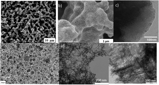 | ||
| Fig. 23 Various nanostructured HTC morphologies: (a) porous carbon monoliths;205 (b) inverse-opal-like carbon;208 (c) F127 soft-templated carbon;210 (d) CarboHIPE emulsion template carbon;211 (e) glucose–phenol carbon aerogel;213 (f) carbon obtained from shrimps shells.215 | ||
In terms of sustainable synthetic practices, the use of templates, whilst advantageous in some respects (e.g., in terms of materials morphology control), is somewhat wasteful. In this regard, HTC carbon aerogels have been synthesised based on an “additive” approach. The additive acts, during the HTC process, to stabilise the formation of small initial carbonaceous nuclei during the early stages of nucleation and cross-link them into 3D interdigitated network with interstitial porosity. Various stabilisers/cross-linkers have been for used for such a purpose including borax,212 and phenols213 (Fig. 23(e)).
The synthesis of carbonaceous monoliths via the HTC platform can also take its inspirations from naturally occurring reaction or biocomposites. In this respect the addition of the glycoprotein, ovalbumine, to the HTC recipe of glucose leads to the formation of very attractive N-doped carbon monoliths. The carbon network is formed via Maillard chemistry between the reducing sugar and protein amine groups, sugar dehydration to HMF and subsequent co-condensation/resinification (e.g., with imines/amadori products) to form an N-doped carbonaceous monolith. The protein degradation and Maillard products act as surface stabilising agents altering the phase separation/demixing of the forming network, promoting the formation of highly porous structures with good nitrogen incorporation (>6 wt% N).214 Regarding biocomposites, the natural hierarchical organisation of CaCO3 nanoparticles and chitin in the exoskeleton of shrimps and lobsters has also been exploited for the synthesis of high surface area (>400 m2 g−1), mesoporous N-doped carbonaceous scaffolds (Fig. 23(f)).215,216
Sponge-like carbogels were recently developed by Wu et al. by a simple one-pot approach directly from the hydrothermal treatment of the soft tissue of watermelon waste.217 This approach does not need any additive since watermelons naturally contain water and carbohydrates. The native watermelon pieces could be easily cut into shapes ranging from 10 mL up to 1 L hydrogels. After drying, low density (∼0.58 g cm−3), flexible, sponge-like aerogels, made of nanospheres/nanofibers together with larger aggregated microparticules, were obtained (Fig. 24). Fe3O4 nanoparticles were subsequently embedded into the gel, via a facile in situ solution approach, leading after further calcination under inert atmosphere to magnetite–carbon hybrid aerogels. Besides the interesting magnetic properties inherent to the supported Fe3O4 nanoparticles, the as-synthesised materials showed excellent specific capacitances when used as electrodes in supercapacitors, up to 330 F g−1 over 1000 cycles at a current density of 1 A g−1. Despite the fact that the watermelon direct approach is simple and inexpensive, the control over the final morphology/porosity is quite limited and closely dependant of the native fruit. In addition, there might be some issues related to the competition with the food chain as it is not clear how much watermelon waste our world is producing, and if this is the right application rather than animal feed.
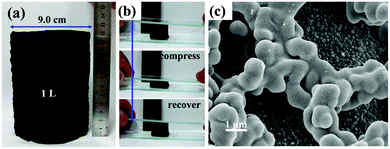 | ||
| Fig. 24 (a) Pictures of a watermelon-derived hydrogel. Mechanical properties (b) and SEM micrograph (c) of the corresponding carbonaceous aerogel. Reproduced with permission from ref. 217. | ||
Another route to sustainable and inexpensive organic aerogels is to substitute the traditional phenolic compounds by non-toxic flavonoids of natural origin. In this context, tannins, widely used in the textile, food and commercial resin industries, have been recently employed as precursors for the sol–gel synthesis of hydrogels based on the hydrothermal polycondensation of the tannin with furfural218,219 or formaldehyde.220,221 Gelation was performed in an oven at 85 °C for 5 days and aerogels were dried with supercritical acetone at 150 °C and 140 bars. After a further thermal treatment at 900 °C under high purity nitrogen, carbon aerogels presenting SBET in the region of 700 m2 g−1, similar to those reported for traditional RF aerogel systems were obtained. The authors calculated the cost of their materials and concluded that they were only one fifth as expensive as traditional aerogels derived from resorcinol, making them the cheapest carbon aerogels ever prepared.220 More recently, Celzard et al. have focused on lowering the amount of formaldehyde involved within the tannin gelation process in order to develop “greener” and cheaper organic aerogels. In this way, two different synthetic procedures were reported: (i) the partial substitution of tannin by lignin, a biopolymer derived from wood;222 and (ii) the use of denatured then formylated soy proteins as natural cross-linkers within wattle tannin-based hydrogels.223 The former synthetic pathway reduced the formaldehyde content to 9.4 wt% (vs. 42.5 wt% for tannin–formaldehyde aerogels220), while conserving relatively high SBET (i.e., 478 m2 g−1) for the organic aerogel product. The tannin gelation approach was recently transferred to produce polyHIPEs, foams and hybrid polyHIPE-foam materials.224 After carbonization at 900 °C, macrocellular carbon monoliths with >97% total porosity could be obtained. The green or sustainable credentials of this synthesis approach are greatly enhanced through the use of sunflower oil as the dispersed phase. Interestingly, the Celzard group has recently combined the HTC and tannin approaches to synthesize nitrogen-doped carbon microspheres.225 Control of the synthetic mixture composition, processing conditions and the use of secondary additives (e.g., proteins) allowed a variety of interesting carbonaceous xero- and aerogel materials and represents a very interesting development in the field of biomass-derived porous carbonaceous materials (Fig. 25).226–228 These reports open new opportunities for the design of sustainable carbogels, particularly via the hydrothermal “tannin-sugar” approach.
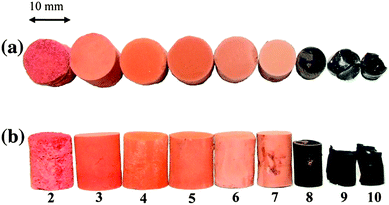 | ||
| Fig. 25 Pictures of xerogels prepared from the gelation of a tannin-based resin at different pHs in the presence of F127 Pluronic surfactant – pHs ranging from 2 to 10: (a) top view; (b) side view. Reproduced with permission from ref. 230. | ||
The initial low temperature (130–220 °C) of the hydrothermal synthesis generates materials with low levels of structural condensation and oxygenated functionalities (e.g., COOH and OH). Therefore HTC materials are typically hydrophilic and the surface functionality can be relatively easily modified with desired compounds, such as polymers.229 Thus, we successfully modified HTC materials with amines,230 thermoresponsive polymers,229 or even redox polymer/glucose oxidase biocatalytic mixtures.211 Besides post modification, HTC materials can also be functionalised in a one-step manner based on the introduction of suitable polymerisation partners (e.g., acrylic acid or vinyl imidazole) to introduce additional material functionality (e.g., carboxylic acid or imidazolium groups).231,232
N-doped carbons are being increasingly recognised for their remarkable properties including enhanced conductivity, performance in rechargeable batteries and intrinsic catalytic activity in electrochemical reactions (e.g., the oxygen reduction reaction (ORR) in fuel cells).233 Various types of N-doped carbons have been prepared via one-step HTC approaches.234 Aside from the benefits of the low temperature synthesis, the chemistry of reducing sugars and amines groups (e.g., Maillard- or Strecker-type reactions) can be utilised to facilitate the introduction of significant nitrogen content in the final material.235 As the nitrogen is covalently incorporated into the structure, it remains part of the material after further thermal carbonisation treatment and can be employed to enhance conductivity. This is in contrast to solely pyrolysis-based synthetic approaches that often result in a substantial reduction in relative nitrogen content with increasing temperature. The HTC process allows the production of various sustainable N-doped carbon materials from numerous precursors such as glucosamine,236 amminated tannin,226 chitosan and chitin,237 algae,238 carbohydrates–protein mixtures,214 amongst others. These materials have subsequently found applications in CO2 adsorption239 and metal free electrocatalysis.240
Given the bottom-up nature of the HTC approach, a variety of hybrid materials have been synthesised based on the incorporation or coating of a variety of inorganic nanostructures and nanoparticles, achieved via post- or in situ synthesis approaches. Perhaps the best example of post-synthesis strategy is the preparation of Te@carbonaceous composite nanocables by coating pre-formed Te nanowires of several nanometer diameters (Fig. 26(a)).241 The Te nanowires can be subsequently removed if desired via dissolution resulting in the production of ultralong hollow carbon fibres. These structures can be further decorated with various noble metal NPs (e.g., Pd, Pt or Au),242 based on simple redox chemistry between the noble metal salt precursor and the HTC surface functionality.177
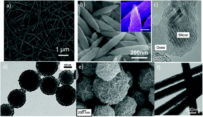 | ||
| Fig. 26 Various HTC–inorganic hybrid materials: (a) HTC@Te nanowires;241 (b) Fe3O4 nanoparticles coated with HTC;243 (c) SiO2@Si@C nanocomposites;244 (d) layer-by-layer HTC spheres decorated with Au nanoparticles;245 (e) MnO2 hollow spheres using hard HTC spheres as templates;246 (f) Ag@cross-linked PVA@HTC coaxial nanocables.247 | ||
Besides Te nanowires, other inorganic materials can be used as substrates for HTC coating including energy-related materials such as Fe3O4 NPs (Fig. 26(b)). The resulting composite was found to be a superior anode material for Li-ion battery electrodes (relative to bare, uncoated Fe3O4 NPs).243 Similarly, Si NPs can be coated with HTC carbon, followed by a thermal carbonisation step, leading to the preparation of materials exhibiting remarkable performance in Li-ion battery applications (Fig. 26(c)).244 HTC materials have also been found to self-assemble with various NPs (e.g., citrate-stabilized Au NPs) via electrostatic interactions and subsequently applied in the fabrication of biosensors (Fig. 26(d)).245
Performing the HTC of glucose in the presence of various inorganic salts has been found to produce a variety of HTC/metal/metal oxide NPs, as a result of the reductive properties of glucose. The HTC part in the resulting hybrids can, if desired, be removed (i.e., to act as templates for the production of nanostructured hollow spheres (Fig. 26(e))).246 An interesting work in this regard is the poly(vinyl alcohol) (PVA)-assisted synthesis of coaxial Ag nanocables (Fig. 26(f)),247 which have been shown to pack in a parallel fashion, forming a bundle structure. This approach has since been extended to synthesis of Cu@cross-linked PVA fibres forming this time a necklace-like Cu@cross-linked PVA coaxial cable-based structure.248
5.4 Applications of hydrothermal carbons in energy storage
Some metals and semiconductors are known to react through electrochemical processes with Li to form alloys according to general formula, LixMy.253–255 The reaction is partially reversible and involves a large number of atoms per formula unit. The specific volumetric and gravimetric capacities exceed those of graphite. For example Li4.4Sn has a gravimetric capacity of 993 vs. 372 mA h g−1 for graphite. The corresponding values for Li4.4Si are 4200 mA h g−1 owing to their high theoretical capacities; many efforts have been made to apply such materials as anodes in Li-ion batteries. However such alloying reactions are normally associated with severe volume changes during lithium insertion–extraction leading to a very fast decay in capacity with cycling. In order to overcome these problems, a thin layer of HTC material has been employed to coat Si NPs to inhibit volume change during Li insertion–desertion and improve the electrical conductivity.244 Such hybrid materials exhibited remarkable performance in LIBs with an excellent cycling performance. The reversible capacity was as high as 1100 mA h g−1 at a current density of 150 mA h g−1 with no capacity decay even after 60 cycles.
Whilst LIBs are commonly employed, the highest energy storage possible is insufficient for the long-term needs of society (e.g., in extended-range electrical vehicles). One solution to increase the overall capacity might be the development of Li–S batteries (LSBs).256,257 LSBs function using a different principle than LIBs, whereby the cathode is formed of elemental S and the anode is metallic Li.258 Under battery operation, S reacts reversibly with Li forming polysulfides which ideally should regenerate the sulfur cathode. The theoretical capacity for this reaction is 1675 mA h g−1. Thus, compared with intercalation cells, LSBs have the opportunity to provide a significantly higher energy density. However, LSBs currently face several challenges that potentially can inhibit their large scale commercialisation. These problems mainly relate to the fact that the polysulfides generated at the cathode during discharging are soluble in the electrolyte and thus migrate to the anode where they can react with the Li electrode to form lower-order polysulfides. They are subsequently transported back to the S cathode and regenerate the higher form of polysulfides. Such a “shuttle” process decreases the overall active material mass utilisation during discharge and leads to poor cyclability and reduced columbic efficiency.
Some of these challenges can be overcome by using nanostructured sulfur–mesoporous carbon composites as demonstrated by Nazar et al.260 In this context, HTC hollow spheres prepared using SiO2 hard templates have been infiltrated with S and used as a LSB cathode (Fig. 27(a) and (b)).259 Two different infiltration procedures were used: melt diffusion and simple physical mixing. These two hollow spheres materials loaded with S were compared with a non-porous HTC material also loaded with S. Stable cycling properties can be obtained when using the nanostructured hollow spheres (Fig. 27(c)), suggesting that the highly porous shell acts as an adsorbent for soluble polysulfides. Finally, the rate capability of this hollow sphere/S cathode was investigated and a remarkably higher specific power was observed as compared with traditional HTC microspheres. (Fig. 27(d)).
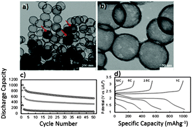 | ||
| Fig. 27 TEM images (a–b) of carbon-based hollow spheres obtained after HTC at 180 °C in presence of glucose, pyrolysis at 950 °C and silica removal, 950-CarbHS-G. Red arrows highlight the presence of residual silica within the carbon hollow spheres. (c) Cycling performances at 1 C for various electrodes using hydrothermal carbons. The cycling stability of the HS HTC–S composite made by melt diffusion method is indicated by circles. The cycling performance of the simple mixture of HS HTC–S is indicated by squares, while the one associated with the mixture of HTC non-hollow microspheres and S is indicated by triangles. (d) Rate performance for HS-HTC–S composite prepared by melt diffusion. The specific capacity was calculated based on the mass of sulfur. Reproduced with permission from ref. 259. | ||
In this context, as a solution to increase activity towards the ORR and provide a long-term alternative to Pt, a variety of non-noble metals have been investigated as promising cathode catalysts. The choice of suitable materials for this purpose is obviously restricted by the conditions required to obtain a long lifetime under the working conditions of a FC. Since Jasinski's first report on the ORR catalytic activity of cobalt phthalocyanines,263 transition metal porphyrins have been thoroughly studied as potential candidates for active and reliable catalysts for fuel cell cathodes.264,265 More recently N-doped carbons have received considerable interest either as supports for non-precious metal catalysts or as catalysts themselves. They can either enhance the ORR reaction for non-precious metal catalysts,266 or show methanol tolerant oxygen reduction (in the case of direct methanol FCs).267 Significantly N-doped carbons have been shown to have catalytic properties themselves, importantly in the absence of any metal.268,269 Thus the development of N-doped (and other heteroatom-doped) carbons in the context of FC chemistry has recently become a hot topic.270–273
In the context of sustainable carbons and more specifically the HTC synthesis platform, hydrothermal carbons have been employed as catalyst supports or catalysts with intrinsic properties for both anodic methanol oxidation (e.g., in direct methanol FCs).274–276 With specific regard to heteroatom-doped materials, complementarily to N doping, S is also now receiving increasing attention in the development of suitable metal-free ORR catalysts. Overall, reports suggest that N-doping is preferred in terms of tuning the electrode's electronic properties, whereas S, as a consequence of its larger size, has been used employed more frequently in applications where its easily polarizable lone pairs (and thus chemical reactivity) are of importance. As an extension of the previously discussed N-doped carbon aerogels,214 Wohlgemuth et al. showed that dual doping with both N and S enables a better electrocatalytic activity compared with solely N-doped carbons in the ORR (Fig. 28).240 In 0.1 M KOH, the performance of the doped aerogels is comparable with that of Pt@C. Compared to Vulcan, the solely nitrogen doped carbon shows an improved onset potential of −185 mV as well as slightly improved current densities within the scanned potential range. The onset potential of the sulfur and nitrogen containing aerogels is more positive and the maximum current density is considerably higher than for Vulcan (Fig. 28(c)). The chronoamperic responses (12![[thin space (1/6-em)]](https://www.rsc.org/images/entities/char_2009.gif) 000 s at a constant rotation speed of 1600 rpm) of all aerogels and Pt@C in O2-saturated 0.1 M KOH show that all aerogels exhibit better stability than Pt@C (Fig. 28(d)). Based on mechanistic discussion in the literature for solely N- and S-doped carbons, a synergistic mechanism between S and N was proposed, whereby N activates the O2 (either directly or indirectly via the adjacent carbon atom), while S facilitates proton transfer during the reduction process. However, careful theoretical studies are necessary in order to understand the electron transfer process and the role of each individual dopant as well as the synergetic effect.
000 s at a constant rotation speed of 1600 rpm) of all aerogels and Pt@C in O2-saturated 0.1 M KOH show that all aerogels exhibit better stability than Pt@C (Fig. 28(d)). Based on mechanistic discussion in the literature for solely N- and S-doped carbons, a synergistic mechanism between S and N was proposed, whereby N activates the O2 (either directly or indirectly via the adjacent carbon atom), while S facilitates proton transfer during the reduction process. However, careful theoretical studies are necessary in order to understand the electron transfer process and the role of each individual dopant as well as the synergetic effect.
5.5 Perspectives on hydrothermal carbonization
Hydrothermal carbonization (HTC) has proven to be a powerful method to synthesise various carbon nanostructures with applications ranging from advanced carbon materials and tailored chemicals to fertilizers and solid fuels for decentralized bioenergy. There are still many challenges to overcome, however, and this can only be achieved by understanding the fundamental chemistry behind this complex process.In the context of advanced carbon materials, it is not yet clear how these materials form. What are the chemical reactions leading to the formation of HTC materials? How does nucleation occur and how can the final particle size be controlled? How do the temperature, pressure and pH affect the resulting carbon morphology and the final chemical structure? Can these materials be made porous and conductive in one simple hydrothermal treatment step?
The direct use of lignocellulosic biomass and waste materials is very challenging due to its heterogeneous nature, even when the same source of biomass is used. Therefore, in order to understand how to process lignocellulosic biomass without any pre-treatment/separation, we need to understand the role of each individual component. Most studies of HTC have used glucose as a precursor, and this may be too simplistic to model HTC of more complex biomolecules. A great deal of research effort is currently dedicated toward understanding the conversion of cellulose into nanostructured materials while lignin is still mostly ignored.
Many questions and challenges concerning HTC remain: can we use the inorganic materials already existing in the lignocellulosic biomass as an in situ activation source for the direct production of highly porous carbon nanomaterials? And if so, is this process reproducible? What is the best application of the HTC process? Advanced carbons, fertilizers, bioenergy, chemicals or a combination of these? If the answer is a combination, how can this process become feasible and sustainable on a large scale? What does the liquid phase contain after the HTC process? Can we efficiently extract valuable chemicals from the liquid phase to improve the economics and environmental impact of the HTC process? Can we minimise amount of water used and recycle the water after we have extracted all the valuable products? Are there any harmful products produced and how do they affect our daily life?
HTC is a very new process with many unanswered questions. Even the simple synthesis of carbon materials via HTC is poorly understood, and things become much more complex when trying to understand and optimise their applicability. More research is urgently needed to address these issues and to ensure a strong future for carbon materials from HTC.
6. Chiral carbon materials derived from biopolymer chiral nematic phases
Biomolecules that are used as sustainable precursors for carbon materials – chitin, cellulose, oligosaccharides – are mostly chiral substances. This chirality stems from the presence of stereocentres in their structures. Many nanocrystalline biomaterials are also known to have morphological chirality on their surfaces, as exemplified by the screw-like morphology of cellulose nanocrystals (CNCs). It is intriguing to consider the development of a chiral carbon material where chirality transfer occurs from the molecular or supramolecular chirality of the biomolecules to the carbon product. There are very few examples of chiral carbon materials that are known (e.g., fullerenes).277 Indeed chiral nanotubes may be useful for developing sensors that respond to single enantiomers, but to date they have proven impossible to prepare as an enantiopure bulk product.278 Creating chiral porous carbons from biomolecules may lead to new opportunities in stereoselective adsorption/separation, sensing of enantiomers, and stereoselective (electro)catalysis. Although the morphology of biomolecules is often retained during carbonization,215,216,278–280 the transfer of chirality from the biomolecule to the carbon product has proven elusive. This is not surprising considering the extensive bond-breaking, bond-forming, and reorganization that occur in conjunction with elimination of water and carbon dioxide during calcination of biomolecules.Cellulose and chitin nanofibres have been shown to form lyotropic liquid crystalline phases in water that can be retained in films after water evaporation.281,282 In these films, the rod-shaped particles of cellulose or chitin are organized into a lamellar structure where the orientation of the nanofibers in each layer rotates through the film (Fig. 29). In fact, this hierarchical structure is similar to the organization of cellulose in the fruit of Pollia condensata and chitin in the cuticles of Scarabaeid beetles;283,284 in the solid-state, the organization is often referred to as a Bouligand structure.285 The orientation of the rods (the director) rotates in either a left-handed or right-handed direction, rendering the assembly chiral. Utilising this chiral nematic assembly as a template for creating chiral carbon materials is an attractive concept. In fact, White et al. proposed that chiral nematic chitin assemblies may potentially be converted to chiral carbon nanostructures.215 However, this has not yet been demonstrated with chitin.
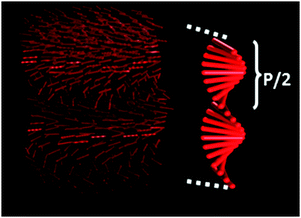 | ||
| Fig. 29 Illustration of chiral nematic order in CNC films. The CNCs have alignment within each layer, but their orientation twists through the stack. Selective diffraction of light occurs when its wavelength, λ, matches n(P/2), where n is the refractive index and P/2 is the half pitch of the structure. Taken with permission from ref. 287. | ||
In 2011, MacLachlan and coworkers reported the synthesis of a chiral nematic form of carbon using cellulose as the precursor.286 Initially, films of CNCs, organised as a chiral nematic assembly, were calcined in order to prepare porous carbon films. Unfortunately, the microporous carbon obtained by this simple approach showed no evidence for retention of the chiral structure as determined by electron microscopy.
Carbonisation of the CNCs entrapped in a silica matrix proved to be the key to capturing the chiral nematic order of the cellulose (Fig. 30). First, CNCs were combined with Si(OMe)4 in water. After evaporation and drying in a petri dish, a composite film of CNCs–silica was obtained.287 Circular dichroism (CD) spectroscopy, SEM, and UV-visible spectroscopy confirmed that the chiral nematic order of the cellulose was retained within the composite. Upon calcination of the composite at 900 °C, the cellulose was transformed into carbon (∼30% yield) within the silica matrix. The material appeared iridescent, indicating the presence of the chiral nematic order (Fig. 31(a)). After etching the silica with NaOH(aq), freestanding films of carbon were obtained (Fig. 31(b)). At 900 °C, the semiconducting carbon obtained is a mixture of sp2 (graphitic) and sp3 hybridized carbon, and only broad peaks were present in the X-ray diffractogram, confirming that the carbon network itself is amorphous. Gas adsorption measurements indicated that the carbon is mesoporous with pores ∼3 nm in diameter and with a high surface area (∼1500 m2 g−1). The porosity of the carbon films could be modified by changing the proportion of cellulose to silica used in the procedure. Furthermore, large films of chiral nematic mesoporous carbon could be prepared by adding polyols (e.g., glucose) to the preparation of the composite precursors.288
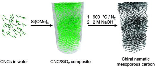 | ||
| Fig. 30 Preparation of chiral nematic mesoporous carbon films (with permission from ref. 286). | ||
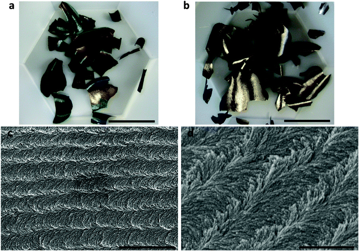 | ||
| Fig. 31 (a) Photograph of the carbon–silica composite after calcination at 900 °C (scale bar = 2 cm). (b) Photograph of the chiral nematic mesoporous carbon films after etching of the silica with NaOH (scale bar = 2 cm). (c) Scanning electron micrograph of the carbon material along a fracture (scale bar = 2 μm) (d) high resolution scanning electron micrograph of the carbon film reveals a twisted fibrous structure (scale bar = 500 nm). Reproduced with permission from ref. 286. | ||
SEM micrographs of the carbon films revealed a twisting, nanofibrillar structure to the carbon that is reminiscent of the chiral nematic silica composites and pure CNC films. These results confirmed that the carbon retained the morphology of the CNC–silica composites and suggested that the chiral nematic structure was transferred to the carbon. Unfortunately, the main characterization tool to prove chiral nematic ordering – CD spectroscopy – could not be performed on the strongly absorbing carbon films. Instead, to prove that the carbon was chiral nematic, it was itself used as a template to prepare thin films of silica. After pyrolysis of the carbon, the resulting silica films showed intense reflections of left-handed circularly polarized light that are diagnostic of the chiral nematic order, thus proving that the mesoporous carbon also has chiral nematic order.
The freestanding films of the synthesised chiral nematic mesoporous carbon proved useful for supercapacitor electrodes as there is no need to add a binder in order to use them. Tuning of the pore size will allow for control of electrolyte diffusion within the structures, an important parameter for tuning the performance of supercapacitors. Applications that utilise the chirality of the carbon, however, have not yet been demonstrated except for its use as a template for other chiral nematic nanomaterials.
Efforts to convert chitin nanofibers into chiral nematic carbon have been met with only limited success. Layered composites of chitin/silica have been prepared that preserve nematic order,289–291 but it has not yet been possible to form chiral nematic composites from released chitin nanocrystals. Calcination of the composites followed by removal of the silica host afforded mesoporous N-doped carbon films that show aligned mesopores by electron microscopy, but no evidence for chirality transfer.292 Very recently, chitin membranes isolated from the cuticles of king crab shells were employed to make chiral nematic mesoporous carbon films, utilizing the natural helicoidal organization present in the cuticle.293
The development of chiral porous carbon materials is still its infancy. As these materials are promising for separations, adsorbents, catalysis, and electrodes, we expect that there will be extensive efforts to develop new forms of porous carbon with chiral structures. Whilst the most promising approaches to chiral carbon materials have used chitin and cellulose as precursors, there are numerous other chiral biomolecules (e.g., DNA, RNA, collagen) and synthetic compounds (e.g., helicenes) that could be used. Creating new forms of chiral carbon from sustainable resources and developing their applications – especially ones that take advantage of the chiral superstructure – will be an important challenge for the future.
7. Other examples of sustainable carbon materials
7.1 Carbon quantum dots
A new family of carbon nanomaterials has recently emerged: carbon quantum dots, also called carbogenic nanodots because of the oxygenated (and other) functional groups, which lowers their carbon content. These intriguing materials are on the order of a few nanometers (below 15 nm) in diameter and exhibit excitation wavelength-dependent photoluminescence (PL) behaviour. Although this phenomenon has not yet been understood at a fundamental level, it is believed that such properties are due to a radiative recombination of excitons located at surface energy traps. This is related to their typical core–shell structure containing a graphitized sp2 hybridized core surrounded by polar functional groups. These materials are attracting considerable attention as they represent benign and low-cost alternatives to the classic semiconductor-based quantum dots. Additionally, their polar functional groups allow for easy functionalization and therefore their surface can be decorated with various (bio) molecules.Carbon quantum dots can be prepared by either top-down or bottom-up approaches. The first category normally involves rather harsh methods where larger graphitic materials are “broken” into small C-dots using arc discharge, laser ablation or electrochemical oxidation. The bottom-up approach fits better with the sustainability topic of this review paper, as they are formed from molecular precursors. A comprehensive review on luminescent carbon quantum dots has been recently published by Baker et al.294 Here, we will focus only on “green” examples that utilise renewable precursors, few synthetic steps and low energy consumption methods.
One of the first reports to synthesize “greener” C-dots was a microwave approach where PEG200 and monosaccharides (i.e., glucose, fructose) were heated in water in a 500 W microwave oven for 2–10 min.295 The authors found that the size of the resulting C-dots was dependent on the duration of the microwave carbonization process; the longer the time, the larger the resulting carbon nanoparticles and the longer the emission wavelength. The authors also discovered that the PL properties were not necessarily related to the passivation with PEG 200, although the non-passivated materials exhibited weaker PL properties.
Another report on the aqueous synthesis of C-dots from carbohydrates involved the dehydration of carbohydrates using concentrated sulfuric acid to form bulky carbon materials followed by reflux in HNO3 to break the resulting material into small nanoparticles. This is obviously a combination of bottom-up and top-down approaches, and does not use the mildest or greenest reagents. After neutralization and dialysis, the CQDs were passivated with 4,7,10-trioxa-1,13-tridecanediamine (TTDDA), ethylenediamine, oleylamine or PEG1500N at 120 °C for 72 h under N2.296
Liu et al. explored a one-step synthetic method to produce amino-functionalized fluorescent C-dots by hydrothermal carbonization of chitosan at elevated temperature (180 °C).297 The resulting carbon nanoparticles were monodisperse and had a narrow size distribution (4–7 nm). Furthermore, as they showed a strong UV/Vis adsorption feature centred at 288 nm and exhibited excitation-dependent emission PL properties, the C-dots could be used for bioimaging (Fig. 32).
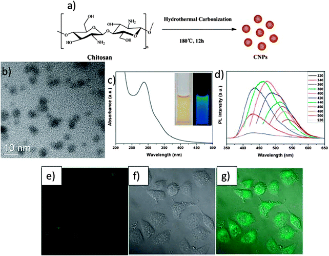 | ||
| Fig. 32 (a) A schematic illustration of the preparation procedure of CNPs by hydrothermal carbonization of chitosan; (b) HRTEM image of CNPs; (c) absorption spectra of the CNPs (inset: photograph of the samples excited by daylight and a 365 UV lamp); (d) emission spectra of the CNPs at different excitation wavelengths as indicated; (e) confocal fluorescence microphotograph of A549 cells labeled with the CNPs at 37 °C for 24 h. (λexc: 405 nm); (f) a brightfield microphotograph of the cells; (g) an overlay image of (e) and (f). Taken with permission from ref. 297. | ||
There are many recent reports on the synthesis of fluorescent carbon quantum dots by hydrothermal carbonization from biomass/waste derivatives such as orange peel waste,298 grass,299 bamboo leaves,300 potato waste,301 or direct pyrolysis of xylitol302 or alginate.303 Most of these publications are related to bioimaging applications and none of them provides a fundamental insight on the PL mechanism.
7.2 Lignin-derived carbons
At present, 98% of lignin is treated as a waste product and is burnt in the process of producing cellulose from wood for the production of paper and cardboard. Lignin is also released when cellulose–ethanol is made from biomass, and it is commonly used as an adhesive in cement. However, lignin is also a perfect alternative for value-added products. Many researchers are now focusing on the conversion of lignin into aromatic chemicals, which can be further used as building blocks in polymer chemistry and other industries.304–307 Efforts directed at the conversion of lignin into carbon materials are far less encountered but represent a rapidly growing research area. Among such materials, lignin-derived carbon fibers play a very important role.Carbon fibers are currently manufactured from polyacrylonitrile (PAN) precursors while small amounts are derived from pitches, notably mesophase pitches (MPP). Unfortunately, owing to the high cost of these petroleum-based precursors and their associated processing costs, carbon fibers remain a specialty product and as such have been limited for use in aerospace, sporting goods, high-end automotive, and specialist industrial applications.
Lignin is the only biopolymer containing large quantities of aromatic, i.e., phenolic moieties, and therefore most suitable for the production of carbon fibers similar to the ones from PAN. Lignin was first investigated as a precursor for carbon fibers in the late 1960s,308 but received very little attention in the following decades. In the 1990s, Sudo et al. modified lignin with hydroxyl groups to obtain carbon fibers with moderate strength and conductivity.309
Recent important investigations on the preparation of lignin-derived carbon fibers come from the Oak Ridge National Laboratory (ORNL) and are focused on hardwood lignin and blends of softwood and hardwood lignin.310–314 More details on lignin-derived carbon fibers prepared using both melt-spinning and electro-spinning, with or without polymer additives, can be found in a recent review paper by the same group,315 and are therefore not discussed here.315
Besides the interest in the production of high-end carbon fibers with similar mechanical properties to the PAN-derived carbon fibers, another objective in research related to lignin-derived carbons is to apply these materials in the field of renewable energy. Lee, Park et al. reported the fabrication of polyacrylonitrile/lignin-based carbon nanofibers by electrospinning (Fig. 33(a)) for high-power lithium ion battery anodes.316 When the content of lignin was increased up to 50 wt%, the fabricated carbon nanofibers exhibited high rate and cycle performances similar to those produced from the PAN precursor (Fig. 33(b)).
There have been several studies on the production of activated carbons using lignin, and a review on this topics can be found in ref. 317. Recently, Ruiz-Rosas et al. published an interesting approach where lignin was used as a precursor for the preparation of hierarchical porous carbon materials using zeolites as hard templates.318 These lignin-based templated carbons have interesting surface chemistry features, such as a variety of surface oxygen groups. Furthermore, they are easily electro-oxidized in a sulfuric acid electrolyte under positive polarization to produce a large amount of surface oxygen groups that boosts the pseudocapacitance. The lignin-based templated carbons showed a specific capacitance as high as 250 F g−1 at 50 mA g−1, with a capacitance retention of 50% and volumetric capacitance of 75 F cm−3 at current densities higher than 20 A g−1 thanks to their suitable porous texture.
Fierro et al. synthesised microporous–mesoporous carbons via colloidal silica templating using Kraft lignin as a carbon precursor.319 A unique feature of these carbons is uniform spherical mesopores achieved after dissolving colloidal silica used as a hard template, while micropores were created by post-synthesis CO2 activation. The resulting activated lignin-based carbons have high specific surface area (up to 2000 m2 g−1) and microporosity and mesoporosity that is easily tuned by adjusting activation conditions and optimizing the amount and particle size of the colloidal silica used. The total pore volumes of activated carbons obtained by using 20 and 13 nm silica colloids as a hard template exceeded 1 and 2 cm3 g−1, respectively.
Dinjus et al. carefully investigated the influence of lignin during the hydrothermal carbonisation of lignocellulosic biomass.320 Similarly, Berge, Libra et al. performed similar studies and discovered that the presence of lignin in bark led to a much lower biochemical oxygen demand (BOD) than lignin in sugar beet and increasing trends of BOD after carbonization. Compared with hydrochars prepared at 200 °C, those prepared at 250 °C were more aromatic and depleted of carbohydrates. Longer residence time (20 h versus 3 h) at 250 °C resulted in the enrichment of nonprotonated aromatic carbons. Both bark and sugar beet pulp underwent deeper carbonization during aqueous hydrothermal carbonization than during steam hydrothermal carbonization (200 °C, 3 h) in terms of more abundant aromatic C but less carbohydrate C in water hydrochars.321
Kang et al. also looked at structural differences between the carbons obtained by hydrothermal carbonization of lignin, xylose, cellulose and wood meal at temperatures between 225–265 °C.322 The hydrochar yield was between 45 and 60%, and the yield trend of the feedstock is lignin > wood meal > cellulose > D-xylose. The hydrochars are stable below 300 °C, and aromatic groups are formed in all of these hydrochars. The C content, C recovery, energy recovery, ratio of C/O, and ratio of C/H in all of these hydrochars are 63–75%, 80–87%, 78–89%, 2.3–4.1, and 12–15, respectively. In terms of the carbonization mechanism, furfural was found to be an important intermediate product during D-xylose hydrochar production, while lignin hydrothermal carbonization products are made of polyaromatic hydrochar and phenolic hydrochar. The formation of microspheres on the surface of cellulose and wood meal hydrochars is discussed, and transformation of the hemicellulose should be responsible for wood meal microsphere production. However, up to now there is no clear study on the final chemical structure of lignin-derived hydrothermal carbons depending on the lignin type and processing conditions.
Given the rapid development of lignocellulosic biomass processing technologies for the second generation of biofuels, we expect that the number of publications related to the use of lignin for the production of low-cost, sustainable carbon materials will increase rapidly in the next few years.
7.3 Other nanostructured carbon materials
The use of cellulose as a precursor for the preparation of aerogel and cryogels is well documented.323 However, the transformation of cellulose aerogels into their carbonaceous or carbon equivalents has not been significantly reported until a short time ago. Wu et al. recently demonstrated the preparation of carbon aerogels using bacterial cellulose as the precursor polysaccharide.324 Whilst the presented CNF aerogels derived from bacterial cellulose have interesting and potentially unique mechanical properties, it is unclear exactly how the morphology of the bacterial cellulose material is retained upon carbonization, given the generally understood thermal decomposition chemistry of polysaccharides (see earlier discussion relating to the synthesis of Starbons®). Another concern here will be the low carbonisation yield resulting from such a methodology, especially in the absence of a carbonisation catalyst. In the field of energy storage, Zhi et al. recently synthesized carbon aerogels from bacterial cellulose and demonstrated their use as an anode in Li-ion batteries in conjunction with deposited SnO2 and Ge nanoparticles.325 With respect to sustainability, bacterial cellulose is normally produced using glucose and used in the food industry, especially in Asia. Therefore, whether the use of bacterial cellulose for making porous carbon materials is truly sustainable is debatable.The leather industry generates voluminous amounts of protein wastes, primarily collagen, at a level of 600 kg per ton of skins/hides processed. Ashokkumar et al. recently produced onion-like nitrogen-doped graphitic structures by simple high temperature carbonization of collagen.326 This synthetic route from bio-waste raw material provides a cost-effective alternative to existing chemical vapor deposition methods for the synthesis of functional nanocarbon materials and is a sustainable approach to tailored nanocarbons for various applications.
Schnepp et al. recently used gelatin left over from various food industries to produce a macroporous carbon gel, controlling the mesopore structure with MgO nanoparticles generated in situ (Fig. 34).327 This approach demonstrates a versatile one-pot synthesis of nitrogen-doped carbons that exploits the templating ability of biological polymers. Starting with just metal nitrates and gelatin, multiphase C/Fe3C/MgO nanomaterials are formed, which are then etched to produce active carbon electrocatalysts with accessible trimodal porosity. The new nanomaterials show remarkable performance in the oxygen reduction reaction – a key process in proton exchange membrane fuel cells.
 | ||
| Fig. 34 One-pot route to C/Fe3C/MgO foams and etching to generate carbon with trimodal porosity. Reproduced with permission from ref. 327. | ||
For more details on the use of biopolymers in materials science, an interesting review on the use of biopolymers as a flexible resource for nanochemistry has been recently published.328
8. Conclusions and outlook
This review intended to provide the reader with an overview of the most recent developments in the field of sustainable carbon materials, highlighting various approaches towards the design and production of nanostructured materials ranging from carbon nanotubes and graphene to some new classes of porous carbon materials such as deep-eutectic solvent-derived carbons, Starbons®, hydrothermal carbons as well as a highly new and exciting family of carbon materials namely porous chiral carbon materials. The application of these carbon materials in a range of important fields of renewable energy and environmental applications have been also described. We have also provided a short perspective summarizing the major successes, limitations and challenges associated with each type of carbon.A significant challenge in materials science at the moment is to quantify sustainability. Materials scientists of the future will need to be creative and realistic and consider all contributions when it comes to designing a truly sustainable material, from precursors to processing (catalysts, number of steps, energy requirements, solvents) to CO2 emissions, harmful releases as well as end of life. Using renewable resources that do not compete with the food chain is clearly important, but it is not the only condition towards making a truly green and sustainable material.
An increased number of materials scientists have understood that sustained research efforts in the field of clean energy are required in order to maintain our current living standards without compromising those of future generations. There are three important elements to be considered while addressing the “sustainable energy trilema”: reducing emissions; improving security of supply; and reducing costs. However, such a transformation to a sustainable society cannot occur without the use of sustainable materials.
We hope that our review paper will be a powerful resource to stimulate a growth in sustainable materials research, particularly to strengthen the efforts towards novel materials for clean energy and environmental applications. This is a Herculean challenge that will require a highly interdisciplinary approach that brings together environmental scientists, economists, social scientists, chemists, materials scientists, theoreticians and engineers.
References
- T. Abbasi and S. A. Abbasi, Renewable Sustainable Energy Rev., 2011, 15, 1828 CrossRef CAS PubMed.
- Q. Zhang, E. Uchaker, S. L. Candelaria and G. Cao, Chem. Soc. Rev., 2013, 42, 3127 RSC.
- N. Linares, A. M. Silvestre-Albero, E. Serrano, J. Silvestre-Albero and J. García-Martínez, Chem. Soc. Rev., 2014 10.1039/c3cs60435g.
- R. Ryoo, S. H. Joo, M. Kruk and M. Jaroniec, Adv. Mater., 2001, 13, 677 CrossRef CAS.
- H. Yang and D. Zhao, J. Mater. Chem., 2005, 15, 1217 CAS.
- A. H. Lu and F. Schüth, Adv. Mater., 2006, 18, 1793 CrossRef CAS.
- R. Ryoo, S. H. Joo and S. Jun, J. Phys. Chem. B, 1999, 103, 7743–7746 CrossRef CAS.
- S. Rondeau-Gagné and J.-F. Morin, Chem. Soc. Rev., 2014, 43, 85 RSC.
- J. H. Clark, J. Chem. Technol. Biotechnol., 2007, 82, 603 CrossRef CAS.
- J. H. Clark, V. Budarin, F. E. I. Deswarte, J. J. E. Hardy, F. M. Kerton, A. J. Hunt, R. Luque, D. J. Macquarrie, K. Milkowski, A. Rodriguez, O. Samuel, S. J. Tavener, R. J. White and A. J. Wilson, Green Chem., 2006, 8, 853 RSC.
- R. Rinaldi and F. Schueth, Energy Environ. Sci., 2009, 2, 610 CAS.
- O. Ioannidou and A. Zabaniotou, Renewable Sustainable Energy Rev., 2007, 11, 1966 CrossRef CAS PubMed.
- R. J. White, V. Budarin, R. Luque, J. H. Clark and D. J. Macquarrie, Chem. Soc. Rev., 2009, 38, 3401–3418 RSC.
- B. Hu, K. Wang, L. Wu, S.-H. Yu, M. Antonietti and M.-M. Titirici, Adv. Mater., 2010, 22, 813–828 CrossRef CAS PubMed.
- M. M. Titirici and M. Antonietti, Chem. Soc. Rev., 2010, 39, 103 RSC.
- D. Mohan and C. U. Pittman, Jr., J. Hazard. Mater., 2006, 137, 762 CrossRef CAS PubMed.
- D. Mohan and C. U. Pittman, Jr., J. Hazard. Mater., 2007, 142, 1 CrossRef CAS PubMed.
- S. Choi, J. H. Dresse and C. W. Jones, ChemSusChem, 2009, 2 CrossRef CAS PubMed.
- A. G. Pandolfo and A. F. Hollenkamp, J. Power Sources, 2006, 157, 11 CrossRef CAS PubMed.
- F. Rodriguez-Reinoso, Carbon, 1998, 36, 159 CrossRef CAS.
- E. Auer, A. Freund, J. Pietsch and T. Tacke, Appl. Catal., A, 1998, 173, 259 CrossRef CAS.
- D. S. Su, ChemSusChem, 2011, 4, 811–813 CrossRef PubMed.
- P. Harris, Carbon Nanotube Science Synthesis, Properties and Applications, Cambridge University Press, 2009 Search PubMed.
- J. P. Tessonnier and D. S. Su, ChemSusChem, 2011, 4, 824–847 CrossRef CAS PubMed.
- Q. Zhang, J. Q. Huang, M. Q. Zhao, W. Z. Qian and F. Wei, ChemSusChem, 2011, 4, 864–889 CrossRef CAS PubMed.
- D. S. Su, ChemSusChem, 2009, 2, 1009–1020 CrossRef CAS PubMed.
- D. S. Su and X. W. Chen, Angew. Chem., Int. Ed., 2007, 46, 1823–1824 CrossRef CAS PubMed.
- D. S. Su, A. Rinaldi, W. Frandsen and G. Weinberg, Phys. Status Solidi B, 2007, 244, 3916–3919 CrossRef CAS.
- M. Endo, K. Takeuchi, Y. A. Kim, K. C. Park, T. Ichiki, T. Hayashi, T. Fukuyo, S. Linou, D. S. Su, M. Terrones and M. S. Dresselhaus, ChemSusChem, 2008, 1, 820–822 CrossRef CAS PubMed.
- A. Rinaldi, J. Zhang, J. Mizera, F. Girgsdies, N. Wang, S. B. A. Hamid, R. Schlogl and D. S. Su, Chem. Commun., 2008, 6528–6530 RSC.
- R. R. Bacsa, P. de Parseval, F. Martin and P. Serp, Carbon, 2013, 64, 219–224 CrossRef CAS PubMed.
- S. Kawasaki, M. Shinoda, T. Shimada, F. Okino and H. Touhara, Carbon, 2006, 44, 2139–2141 CrossRef CAS PubMed.
- X. W. Chen, D. S. Su, S. B. A. Hamid and R. Schlogl, Carbon, 2007, 45, 895–898 CrossRef CAS PubMed.
- X. W. Chen, O. Timpe, S. B. A. Hamid, R. Schlogl and D. S. Su, Carbon, 2009, 47, 340–343 CrossRef CAS PubMed.
- J. G. Zhao, X. Y. Guo, Q. G. Guo, L. Gu, Y. Guo and F. Feng, Carbon, 2011, 49, 2155–2158 CrossRef CAS PubMed.
- A. Rinaldi, J. P. Tessonnier, M. E. Schuster, R. Blume, F. Girgsdies, Q. Zhang, T. Jacob, S. B. A. Hamid, D. S. Su and R. Schlogl, Angew. Chem., Int. Ed., 2011, 50, 3313–3317 CrossRef CAS PubMed.
- R. A. Afre, T. Soga, T. Jimbo, M. Kumar, Y. Ando, M. Sharon, P. R. Somani and M. Umeno, Microporous Mesoporous Mater., 2006, 96, 184–190 CrossRef CAS PubMed.
- P. Ghosh, T. Soga, R. A. Afre and T. Jimbo, J. Alloys Compd., 2008, 462, 289–293 CrossRef CAS PubMed.
- P. Ghosh, R. A. Afre, T. Soga and T. Jimbo, Mater. Lett., 2007, 61, 3768–3770 CrossRef CAS PubMed.
- S. Paul and S. K. Samdarshi, New Carbon Mater., 2011, 26, 85–88 CrossRef CAS.
- R. Kumar, R. S. Tiwari and O. N. Srivastava, Nanoscale Res. Lett., 2011, 6, 90 CrossRef PubMed.
- A. B. Suriani, A. A. Azira, S. F. Nik, R. M. Nor and M. Rusop, Mater. Lett., 2009, 63, 2704–2706 CrossRef CAS PubMed.
- A. B. Suriani, S. Muhamad, P. S. M. Saad, S. A. M. Zobir, R. M. Nor, Y. M. Siran, S. A. M. Rejab, A. J. Asis, S. Tahiruddin, S. Abdullah and M. M. Rusop, Defect Diffus. Forum, 2011, 312–315, 906–911 Search PubMed.
- M. S. Azmina, A. B. Suriani, A. N. Falina, M. Salina, J. Rosly and M. Rusop, in Nanomaterials: Synthesis and Characterization, ed. Z. A. Ahmad, M. A. Yarmo, F. Haji, A. Aziz, M. Y. M. Sulaiman, B. Ahmad, K. N. Ismail, A. R. Jamaludin, M. A. Sulaiman and M. F. A. Rahman, Trans Tech Publications Ltd, Stafa-Zurich, 2012, vol. 364, pp. 408–411 Search PubMed.
- M. Kumar and Y. Ando, Diamond Relat. Mater., 2003, 12, 998–1002 CrossRef CAS.
- A. B. Suriani, A. R. Dalila, A. Mohamed, M. H. Mamat, M. Salina, M. S. Rosmi, J. Rosly, R. M. Nor and M. Rusop, Mater. Lett., 2013, 101, 61–64 CrossRef CAS PubMed.
- S. Glatzel, Z. Schnepp and C. Giordano, Angew. Chem., Int. Ed., 2013, 52, 2355–2358 CrossRef CAS PubMed.
- M. Sevilla and A. B. Fuertes, Chem. Phys. Lett., 2010, 490, 63–68 CrossRef CAS PubMed.
- V. G. Pol and P. Thiyagarajan, J. Environ. Monit., 2010, 12, 455–459 RSC.
- K. S. Novoselov, A. K. Geim, S. V. Morozov, D. Jiang, Y. Zhang, S. V. Dubonos, I. V. Grigorieva and A. A. Firsov, Science, 2004, 306, 666–669 CrossRef CAS PubMed.
- W. S. Hummers and R. E. Offeman, J. Am. Chem. Soc., 1958, 80, 1339 CrossRef CAS.
- C. K. Chua and M. Pumera, Chem. Soc. Rev., 2014, 43, 291–312 RSC.
- G. D. Ruan, Z. Z. Sun, Z. W. Peng and J. M. Tour, ACS Nano, 2011, 5, 7601–7607 CrossRef CAS PubMed.
- A. K. Ray, R. K. Sahu, V. Rajinikanth, H. Bapari, M. Ghosh and P. Paul, Carbon, 2012, 50, 4123–4129 CrossRef CAS PubMed.
- K. Min, T. H. Han, J. Kim, J. Jung, C. Jung, S. M. Hong and C. M. Koo, J. Colloid Interface Sci., 2012, 383, 36–42 CrossRef CAS PubMed.
- X. B. Fan, W. C. Peng, Y. Li, X. Y. Li, S. L. Wang, G. L. Zhang and F. B. Zhang, Adv. Mater., 2008, 20, 4490–4493 CrossRef CAS.
- L. A. L. Tang, W. C. Lee, H. Shi, E. Y. L. Wong, A. Sadovoy, S. Gorelik, J. Hobley, C. T. Lim and K. P. Loh, Small, 2012, 8, 423–431 CrossRef CAS PubMed.
- J. H. Liu, L. Cao and X. Wang, Nano LIFE, 2010, 1, 153–161 CrossRef CAS.
- C. Z. Zhu, S. J. Guo, Y. X. Fang and S. J. Dong, ACS Nano, 2010, 4, 2429–2437 CrossRef CAS PubMed.
- Y. K. Kim, M. H. Kim and D. H. Min, Chem. Commun., 2011, 47, 3195–3197 RSC.
- S. Gurunathan, J. W. Han and J. H. Kim, Int. J. Nanomed., 2013, 8, 2719–2732 CrossRef PubMed.
- S. Gurunathan, J. W. Han, J. H. Park, V. Eppakayala and J. H. Kim, Int. J. Nanomed., 2014, 9, 363–377 CrossRef PubMed.
- S. Bose, T. Kuila, A. K. Mishra, N. H. Kim and J. H. Lee, J. Mater. Chem., 2012, 22, 9696–9703 RSC.
- Q. Zhang, J. Q. Huang, W. Z. Qian, Y. Y. Zhang and F. Wei, Small, 2013, 9, 1237 CrossRef CAS PubMed.
- X. Q. X. Huang, F. Boey and H. Zhang, Chem. Soc. Rev., 2012, 41, 666 RSC.
- D. Eder, Chem. Rev., 2010, 110, 1348–1385 CrossRef CAS PubMed.
- D. Gournis, M. A. Karakassides, T. Bakas, N. Boukos and D. Petridis, Carbon, 2002, 40, 2641–2646 CrossRef CAS.
- A. Bakandritsos, A. Simopoulos and D. Petridis, Chem. Mater., 2005, 17, 3468–3474 CrossRef CAS.
- W. D. Zhang, I. Y. Phang and T. X. Liu, Adv. Mater., 2006, 18, 73–77 CrossRef CAS.
- M. Q. Zhao, Q. Zhang, J. Q. Huang and F. Wei, Adv. Funct. Mater., 2012, 22, 675–694 CrossRef CAS.
- Q. Zhang, M. Q. Zhao, Y. Liu, A. Y. Cao, W. Z. Qian, Y. F. Lu and F. Wei, Adv. Mater., 2009, 21, 2876–2880 CrossRef CAS.
- Q. Zhang, M. Q. Zhao, J. Q. Huang, Y. Liu, Y. Wang, W. Z. Qian and F. Wei, Carbon, 2009, 47, 2600–2610 CrossRef CAS PubMed.
- S. Petit, D. Righl and J. Madejova, Appl. Clay Sci., 2006, 34, 22–30 CrossRef CAS PubMed.
- D. S. Su, X. W. Chen, G. Weinberg, A. Klein-Hofmann, O. Timpe, S. B. A. Hamid and R. Schlogl, Angew. Chem., Int. Ed., 2005, 44, 5488–5492 CrossRef CAS PubMed.
- S. Sen Gupta, T. S. Sreeprasad, S. M. Maliyekkal, S. K. Das and T. Pradeep, ACS Appl. Mater. Interfaces, 2012, 4, 4156–4163 Search PubMed.
- D. S. Su, X. W. Chen, X. Liu, J. J. Delgado, R. Schlogl and A. Gajovic, Adv. Mater., 2008, 20, 3597–3600 CrossRef CAS.
- M. Biswal, A. Banerjee, M. Deo and S. Ogale, Energy Environ. Sci., 2013, 6, 1249–1259 CAS.
- R. W. Pekala, J. Mater. Sci., 1989, 24, 3221–3227 CrossRef CAS.
- A. Taguchi, J. H. Smätt and M. Lindén, Adv. Mater., 2003, 15, 1209–1211 CrossRef CAS.
- S. A. Al-Muhtaseb and J. A. Ritter, Adv. Mater., 2003, 15, 101–114 CrossRef CAS.
- Y. Huang, H. Cai, D. Feng, D. Gu, Y. Deng, B. Tu, H. Wang, P. A. Webley and D. Zhao, Chem. Commun., 2008, 2641–2643 RSC.
- M. C. Gutiérrez, F. Picó, F. Rubio, J. Manuel Amarilla, F. Javier Palomares, M. L. Ferrer, F. Del Monte and J. M. Rojo, J. Mater. Chem., 2009, 19, 1236–1240 RSC.
- X. Zhuang, Y. Wan, C. Feng, Y. Shen and D. Zhao, Chem. Mater., 2009, 21, 706–716 CrossRef CAS.
- Z. Wu, P. A. Webley and D. Zhao, Langmuir, 2010, 26, 10277–10286 CrossRef CAS PubMed.
- D. Carriazo, F. Picó, M. C. Gutiérrez, F. Rubio, J. M. Rojo and F. Del Monte, J. Mater. Chem., 2010, 20, 773–780 RSC.
- D. Carriazo, M. C. Serrano, M. C. Gutiérrez, M. L. Ferrer and F. Del Monte, Chem. Soc. Rev., 2012, 41, 4996–5014 RSC.
- D. C. F. del Monte, M. C. Serrano, M. C. Gutierrez and M. L. Ferrer, ChemSusChem, 2014, 7, 999–1009 CrossRef PubMed.
- A. P. Abbott, G. Capper, D. L. Davies, R. K. Rasheed and V. Tambyrajah, Chem. Commun., 2003, 70–71 RSC.
- A. P. Abbott, R. C. Harris and K. S. Ryder, J. Phys. Chem. B, 2007, 111, 4910–4913 CrossRef CAS PubMed.
- A. P. Abbott, G. Capper and S. Gray, ChemPhysChem, 2006, 7, 803–806 CrossRef CAS PubMed.
- A. P. Abbott, D. Boothby, G. Capper, D. L. Davies and R. K. Rasheed, J. Am. Chem. Soc., 2004, 126, 9142–9147 CrossRef CAS PubMed.
- G. Imperato, E. Eibler, J. Niedermaier and B. König, Chem. Commun., 2005, 1170–1172 RSC.
- G. Imperato, S. Höger, D. Lenoir and B. König, Green Chem., 2006, 8, 1051–1055 RSC.
- G. Imperato, R. Vasold and B. König, Adv. Synth. Catal., 2006, 348, 2243–2247 CrossRef CAS.
- Y. H. Choi, J. van Spronsen, Y. Dai, M. Verberne, F. Hollmann, I. W. C. E. Arends, G. J. Witkamp and R. Verpoorte, Plant Physiol., 2011, 156, 1701–1705 CrossRef CAS PubMed.
- Y. Dai, G. J. Witkamp, R. Verpoorte and Y. H. Choi, Anal. Chem., 2013, 85, 6272–6278 CrossRef CAS PubMed.
- M. Francisco, A. Van Den Bruinhorst and M. C. Kroon, Angew. Chem., Int. Ed., 2013, 52, 3074–3085 CrossRef CAS PubMed.
- D. Carriazo, M. C. Gutiérrez, M. L. Ferrer and F. Del Monte, Chem. Mater., 2010, 22, 6146–6152 CrossRef CAS.
- J. Patiño, M. C. Gutierrez, D. Carriazo, C. O. Ania, J. B. Parra, M. L. Ferrer and F. d. Monte, Energy Environ. Sci., 2012, 5, 8699–8707 Search PubMed.
- M. C. Gutiérrez, D. Carriazo, C. O. Ania, J. B. Parra, M. L. Ferrer and F. Del Monte, Energy Environ. Sci., 2011, 4, 3535–3544 Search PubMed.
- M. C. Gutiérrez, D. Carriazo, A. Tamayo, R. Jiménez, F. Picõ, J. M. Rojo, M. L. Ferrer and F. Del Monte, Chem. – Eur. J., 2011, 17, 10533–10537 CrossRef PubMed.
- E. R. Cooper, C. D. Andrews, P. S. Wheatley, P. B. Webb, P. Wormald and R. E. Morris, Nature, 2004, 430, 1012–1016 CrossRef CAS PubMed.
- D. Carriazo, M. C. Gutiérrez, F. Picó, J. M. Rojo, J. L. G. Fierro, M. L. Ferrer and F. Del Monte, ChemSusChem, 2012, 5, 1405–1409 CrossRef CAS PubMed.
- M. A. Worsley, S. O. Kucheyev, J. D. Kuntz, A. V. Hamza, J. H. Satcher Jr and T. F. Baumann, J. Mater. Chem., 2009, 19, 3370–3372 RSC.
- Y. Tao, D. Noguchi, C. M. Yang, H. Kanoh, H. Tanaka, M. Yudasaka, S. Iijima and K. Kaneko, Langmuir, 2007, 23, 9155–9157 CrossRef CAS PubMed.
- M. A. Worsley, P. J. Pauzauskie, T. Y. Olson, J. Biener, J. H. Satcher Jr and T. F. Baumann, J. Am. Chem. Soc., 2010, 132, 14067–14069 CrossRef CAS PubMed.
- Q. Wang, J. Luo, Z. Zhong and A. Borgna, Energy Environ. Sci., 2011, 4, 42–55 CAS.
- A. Wahby, J. M. Ramos-Fernández, M. Martínez-Escandell, A. Sepúveda-Escribano, J. Silvestre-Albero and F. Rodríguez-Reinoso, ChemSusChem, 2010, 3, 974–981 CrossRef CAS PubMed.
- M. Sevilla and A. B. Fuertes, Energy Environ. Sci., 2011, 4, 1765–1771 CAS.
- G. P. Hao, W. C. Li, D. Qian and A. H. Lu, Adv. Mater., 2010, 22, 853 CrossRef CAS PubMed.
- S. Sircar, T. C. Golden and M. B. Rao, Carbon, 1996, 34, 1–12 CrossRef CAS.
- X. Xu, X. Zhao, L. Sun and X. Liu, J. Nat. Gas Chem., 2008, 17, 391–396 CrossRef CAS.
- Z. Zhang, S. Xian, H. Xi, H. Wang and Z. Li, Chem. Eng. Sci., 2011, 66, 4878–4888 CrossRef CAS PubMed.
- B. Wang, A. P. Côté, H. Furukawa, M. O'Keeffe and O. M. Yaghi, Nature, 2008, 453, 207–211 CrossRef CAS PubMed.
- R. J. White, N. Brun, V. L. Budarin, J. H. Clark and M. M. Titirici, ChemSusChem, 2014, 7, 670–689 CrossRef CAS PubMed.
- G. M. Glenn and D. W. Irving, Cereal Chem., 1995, 72, 155–161 CAS.
- V. Budarin, J. H. Clark, J. J. E. Hardy, R. Luque, K. Milkowski, S. J. Tavener and A. J. Wilson, Angew. Chem., Int. Ed., 2006, 45, 3782–3786 CrossRef CAS PubMed.
- R. J. White, V. L. Budarin and J. H. Clark, ChemSusChem, 2008, 1, 408–411 CrossRef CAS PubMed.
- F. Quignard, R. Valentin and F. D. Renzo, New J. Chem., 2008, 32, 1300–1310 RSC.
- C. A. Garcia-Gonzalez, E. Carenza, M. Zeng, I. Smirnova and A. Rolg, RSC Adv., 2012, 2, 9816–9823 RSC.
- C. A. Garcia-Gonzalez and I. Smirnova, J. Supercrit. Fluids, 2013, 79, 152–158 CrossRef CAS PubMed.
- C. A. Garcia-Gonzalez, J. J. Uy, M. Alnaief and I. Smirnova, Carbohydr. Polym., 2012, 88, 1378–1386 CrossRef CAS PubMed.
- R. R. Mallepally, I. Bernard, M. A. Marin, K. R. Ward and M. A. McHugh, J. Supercrit. Fluids, 2013, 79, 202–208 CrossRef CAS PubMed.
- F. Zhang, Y. Meng, D. Gu, Y. Yan, C. Yu, B. Tu and D. Zhao, J. Am. Chem. Soc., 2005, 127, 13508–13509 CrossRef CAS PubMed.
- R. W. Pekala, J. C. Farmer, C. T. Alviso, T. D. Tran, S. T. Mayer, J. M. Miller and B. Dunn, J. Non-Cryst. Solids, 1998, 225, 74–80 CrossRef CAS.
- R. J. White, V. L. Budarin and J. H. Clark, Chem. – Eur. J., 2010, 16, 1326–1335 CrossRef CAS PubMed.
- R. J. White, C. Antonio, V. L. Budarin, E. Bergström, J. Thomas-Oates and J. H. Clark, Adv. Funct. Mater., 2010, 20, 1834–1841 CrossRef CAS.
- N. B. C. Falco and M. M. Titirici, Green Chem., 2011, 13, 3273–3281 RSC.
- A. Buleon, P. Colonna, V. Planchot and S. Ball, Int. J. Biol. Macromol., 1998, 23, 85–112 CrossRef CAS.
- P. S. Shuttleworth, V. Budarin, R. J. White, V. M. Gun'ko, R. Luque and J. H. Clark, Chem. – Eur. J., 2013, 19, 9351–9357 CrossRef CAS PubMed.
- Y. Liang, F. Liang, Z. Li, D. Wu, F. Yan, S. Li and R. Fu, Phys. Chem. Chem. Phys., 2010, 12, 10842–10845 RSC.
- Y. Liang, F. Liang, D. Wu, Z. Li, F. Xu and R. Fu, Phys. Chem. Chem. Phys., 2011, 8852–8856 RSC.
- E. D. T. Atkins, I. A. Nieduszynski, W. Mackie, K. D. Parker and E. E. Smolko, Biopolymers, 1973, 12, 1879–1887 CrossRef CAS PubMed.
- D. F. Pindar and C. Bucke, Biochem. J., 1975, 152, 617–622 CAS.
- J. E. Scott, Biochim. Biophys. Acta, 1968, 170, 468–473 CrossRef.
- S. T. Moe, G. Skjak-Braek, A. Elgsaeter and O. Smidsrod, Macromolecules, 1993, 26, 3589–3597 CrossRef CAS.
- A. L. Ching, C. V. Liew, L. W. Chan and P. W. S. Heng, Eur. J. Pharm. Sci., 2008, 33, 361–370 CrossRef CAS PubMed.
- J. R. Dodson, V. L. Budarin, A. J. Hunt, P. S. Shuttleworth and J. H. Clark, J. Mater. Chem. A, 2013, 1, 5203–5207 CAS.
- J. H. Knox and P. Ross, Adv. Chromatogr., 1997, 37, 73–119 CAS.
- E. Forgacs, J. Chromatogr. A, 2002, 975, 229–243 CrossRef CAS.
- L. Pereira, J. Liq. Chromatogr. Relat. Technol., 2008, 31, 1687–1731 CrossRef CAS.
- C. Antonio, C. Pinheiro, M. M. Chaves, C. P. Ricardo, M. F. Ortuño and J. Thomas-Oates, J. Chromatogr. A, 2008, 1187, 111–118 CrossRef CAS PubMed.
- C. Antonio, T. Larson, A. Gilday, I. Graham, E. Bergström and J. Thomas-Oates, J. Chromatogr. A, 2007, 1172, 170–178 CrossRef CAS PubMed.
- E. B. A. S. Marriott, A. J. Hunt, J. Thomas-Oates and J. H. Clark, RSC Adv., 2014, 4, 222–228 RSC.
- E. R. Morris, G. T. Grant, D. A. Rees, P. J. C. Smith and D. Thom, FEBS Lett., 1973, 32, 195–198 CrossRef.
- A. S. Marriott, A. J. Hunt, E. Bergström, K. Wilson, V. L. Budarin, J. Thomas-Oates, J. H. Clark and R. Brydson, Carbon, 2014, 67, 514–524 CrossRef CAS PubMed.
- H. L. Parker, A. J. Hunt, V. L. Budarin, P. S. Shuttleworth, K. L. Miller and J. H. Clark, RSC Adv., 2012, 2, 8992–8997 RSC.
- J. Avom, K. J. Mbadcam, C. Noubactep and P. Germain, Carbon, 1997, 35, 365–369 CrossRef CAS.
- K. K. H. Choy, G. McKay and J. F. Porter, Resour., Conserv. Recycl., 1999, 27, 57–71 CrossRef.
- B. H. Hameed, A. L. Ahmad and K. N. A. Latiff, Dyes Pigm., 2007, 75, 143–149 CrossRef CAS PubMed.
- M. Streat, J. W. Patrick and M. J. Camporro-Perez, Water Res., 1995, 29, 467–472 CrossRef CAS.
- L. J. Kennedy, J. J. Vijaya, G. Sekaran and K. Kayalvizhi, J. Hazard. Mater., 2007, 149, 134–143 CrossRef CAS PubMed.
- H. L. Parker, V. L. Budarin, J. H. Clark and A. J. Hunt, ACS Sustainable Chem. Eng., 2013, 1, 1311–1318 CrossRef CAS.
- V. L. Budarin, R. Luque, D. J. Macquarrie and J. H. Clark, Chem. – Eur. J., 2007, 13, 6914–6919 CrossRef CAS PubMed.
- V. Budarin, R. Luque, J. H. Clark and D. J. Macquarrie, Chem. Commun., 2007, 634–636 RSC.
- R. Luque, J. H. Clark, K. Yoshida and P. L. Gai, Chem. Commun., 2009, 5305–5307 RSC.
- R. Luque and J. H. Clark, Catal. Commun., 2010, 11, 928–931 CrossRef CAS PubMed.
- J. M. Bermudez, J. A. Menéndez, A. A. Romero, E. Serrano, J. Garcia-Martinez and R. Luque, Green Chem., 2013, 15, 2786–2792 RSC.
- C. S. K. Lin, R. Luque, J. H. Clark, C. Webb and C. Du, Energy Environ. Sci., 2011, 4, 1471–1479 CAS.
- R. Luque and J. H. Clark, ChemCatChem, 2011, 3, 594–597 CrossRef CAS.
- R. Luque, V. Budarin, J. H. Clark, P. S. Shuttleworth and R. J. White, Catal. Commun., 2011, 12, 1471–1476 CrossRef CAS PubMed.
- J. C. Colmenares, P. Lisowski and D. Łomot, RSC Adv., 2013, 3, 20186–20192 RSC.
- http://www.starbon-technologies.com/ .
- V. Budarin, J. H. Clark, R. Luque and R. J. White, Mater. Matters, 2009, 4, 19–22 CAS.
- F. Bergius, Zeitschrift fur Komprimierte und Flussige Gase, 1915, 17 CAS.
- F. Bergius, Naturwissenschaften, 1928, 16, 1–10 CrossRef CAS.
- J. A. Rice, Soil Sci., 2001, 166, 848–857 CrossRef CAS PubMed.
- F. Bergius, J. Soc. Chem. Ind., 1913, 32 CrossRef.
- F. Bergius, Z. Ver. Dtsch. Ing., 1925, 69, 1359–1362 Search PubMed.
- F. Bergius, Z. Elektrochem., 1912, 18 CAS.
- M. W. Haenel, Fuel, 1992, 71, 1211–1223 CrossRef CAS.
- E. Berl and A. Schmidt, Justus Liebigs Ann. Chem., 1928, 461, 192–220 CrossRef CAS.
- E. Berl, A. Schmidt and H. Koch, Angew. Chem., 1932, 45, 517–519 CrossRef CAS.
- J. P. Schuhmacher, H. A. Vanvucht, M. P. Groenewege, L. Blom and D. W. Vankrevelen, Fuel, 1956, 35, 281–290 CAS.
- J. P. Schuhmacher, F. J. Huntjens and D. W. Vankrevelen, Fuel, 1960, 39, 223–234 CAS.
- Q. Wang, H. Li, L. Chen and X. Huang, Carbon, 2001, 39, 2211–2214 CrossRef CAS.
- X. Sun and Y. Li, Angew. Chem., Int. Ed., 2004, 43, 597–601 CrossRef PubMed.
- S. H. Yu, X. J. Cui, L. L. Li, K. Li, B. Yu, M. Antonietti and H. Colfen, Adv. Mater., 2004, 16, 1636–1640 CrossRef CAS.
- H. S. Qian, S. H. Yu, L. B. Luo, J. Y. Gong, L. F. Fei and X. M. Liu, Chem. Mater., 2006, 18, 2102 CrossRef CAS.
- M. M. Titirici, Sustainable Carbon Materials via Hydrothermal Processes, Wiley, 2013 Search PubMed.
- L. Wei, M. Sevilla, A. B. Fuertes, R. Mokaya and G. Yushin, Adv. Energy Mater., 2011, 1, 356–361 CrossRef CAS.
- M. Sevilla, J. A. Macia-Agullo and A. B. Fuertes, Biomass Bioenergy, 2011, 35, 3152–3159 CrossRef CAS PubMed.
- M. Sevilla and A. B. Fuertes, Carbon, 2009, 47, 2281–2289 CrossRef CAS PubMed.
- N. D. Berge, K. S. Ro, J. Mao, J. R. V. Flora, M. A. Chappell and S. Bae, Environ. Sci. Technol., 2011, 45, 5696–5703 CrossRef CAS PubMed.
- N. Berge, K. Ro, K. Kammann and J. Libra, in Sustainable Carbon Materials from Hydrothermal Processes, ed. M. Titirici, Wiley, 2013 Search PubMed.
- A. Funke and F. Ziegler, Biofuels, Bioprod. Biorefin., 2010, 4, 160–177 CrossRef CAS.
- E. Dinjus, A. Kruse and N. Tröger, Chem. Eng. Technol., 2011, 34, 2037–2043 CrossRef CAS.
- X. Lu, B. Jordan and N. D. Berge, Waste Manage., 2012, 32(7), 1353–1365 CrossRef CAS PubMed.
- F. B. A. Kruse, R. Grandl and D. Wüst, Chem. Ing. Tech., 2012 Search PubMed.
- S. K. Hoekman, A. Broch and C. Robbins, Energy Fuels, 2011, 25, 1802–1810 CrossRef CAS.
- S. M. Heilmann, L. R. Jader, L. A. Harned, M. J. Sadowsky, F. J. Schendel, P. A. Lefebvre, M. G. von Keitz and K. J. Valentas, Appl. Energy, 2011, 88, 3286–3290 CrossRef CAS PubMed.
- S. M. Heilmann, H. T. Davis, L. R. Jader, P. A. Lefebvre, M. J. Sadowsky, F. J. Schendel, M. G. von Keitz and K. J. Valentas, Biomass Bioenergy, 2010, 34, 875–882 CrossRef CAS PubMed.
- S. K. Hoekman, A. Broch and C. Robbins, Energy Fuels, 2011, 25, 1802–1810 CrossRef CAS.
- N. Baccile, G. Laurent, F. Babonneau, F. Fayon, M.-M. Titirici and M. Antonietti, J. Phys. Chem. C, 2009, 113, 9644–9654 CAS.
- D. G. Cory, Chem. Phys. Lett., 1988, 152, 431–434 CrossRef CAS.
- B. Elena, A. Lesage, S. Steuernagel, A. Bockmann and L. Emsley, J. Am. Chem. Soc., 2005, 127, 17296–17302 CrossRef CAS PubMed.
- M. M. Titirici, M. Antonietti and N. Baccile, Green Chem., 2008, 10, 1204–1212 RSC.
- M. Zhang and A. A. Ogale, Carbon, 2014, 69, 626–629 CrossRef CAS PubMed.
- C. Falco, N. Baccile and M.-M. Titirici, Green Chem., 2011, 13, 3273–3281 RSC.
- X. Lu, P. J. Pellechia, J. R. V. Flora and N. D. Berge, Bioresour. Technol., 2013, 139, 180–190 CrossRef PubMed.
- C. Falco, F. Perez Caballero, F. Babonneau, C. Gervais, G. Laurent, M.-M. Titirici and N. Baccile, Langmuir, 2011, 27, 14460–14471 CrossRef CAS PubMed.
- X. Cao, K. S. Ro, M. Chappell, Y. Li and J. Mao, Energy Fuels, 2010, 25, 388–397 CrossRef.
- L. Yu, C. Falco, J. Weber, R. J. White, J. Y. Howe and M.-M. Titirici, Langmuir, 2012, 28, 12373–12383 CrossRef CAS PubMed.
- M. M. Titirici, A. Thomas and M. Antonietti, Adv. Funct. Mater., 2007, 17, 1010–1018 CrossRef CAS.
- L. H. Yu, N. Brun, K. Sakaushi, J. Eckert and M. M. Titirici, Carbon, 2013, 61, 245–253 CrossRef CAS PubMed.
- S. Kubo, I. Tan, R. J. White, M. Antonietti and M.-M. Titirici, Chem. Mater., 2010, 22, 6590–6597 CrossRef CAS.
- R. J. White, K. Tauer, M. Antonietti and M.-M. Titirici, J. Am. Chem. Soc., 2011, 132, 17360–17363 CrossRef PubMed.
- S. Kubo, R. J. White, K. Tauer and M. M. Titirici, Chem. Mater., 2013, 25, 4781–4790 CrossRef CAS.
- C. Liang, K. Hong, G. A. Guiochon, J. W. Mays and S. Dai, Angew. Chem., Int. Ed., 2004, 43, 5785–5789 CrossRef CAS PubMed.
- S. Kubo, R. J. White, N. Yoshizawa, M. Antonietti and M.-M. Titirici, Chem. Mater., 2011, 23, 4882–4885 CrossRef CAS.
- N. Brun, L. Edembe, S. Gounel, N. Mano and M. M. Titirici, ChemSusChem, 2013, 6, 701–710 CrossRef CAS PubMed.
- T.-P. Fellinger, R. J. White, M.-M. Titirici and M. Antonietti, Adv. Funct. Mater., 2012, 22, 3254–3260 CrossRef CAS.
- N. Brun, S. Wohlgemuth, P. Osiceanu and M. Titirici, Green Chem., 2013, 15, 2514 RSC.
- R. J. White, N. Yoshizawa, M. Antonietti and M.-M. Titirici, Green Chem., 2011, 13, 2428–2434 RSC.
- R. J. White, M. Antonietti and M.-M. Titirici, J. Mater. Chem., 2009, 19, 8645–8650 RSC.
- M. Soorholtz, R. J. White, T. Zimmermann, M.-M. Titirici, M. Antonietti, R. Palkovits and F. Schuth, Chem. Commun., 2013, 49, 240–242 RSC.
- X. Wu, T. Wen, H. Guo, S. Yang, X. Wang and A. Xu, ACS Nano, 2013, 7, 3589–3597 CrossRef CAS PubMed.
- K. Kraiwattanawong, S. Mukai, H. Tamon and A. Lothongkum, Microporous Mesoporous Mater., 2007, 98, 258–266 CrossRef CAS PubMed.
- K. Kraiwattanawong, S. Mukai, H. Tamon and A. Lothongkum, J. Porous Mater., 2008, 15, 695–703 CrossRef CAS.
- A. Szczurek, G. Amaral-Labat, V. Fierro, A. Pizzi, E. Masson and A. Celzard, Carbon, 2011, 49, 2773–2784 CrossRef CAS PubMed.
- A. Szczurek, G. Amaral-Labat, V. Fierro, A. Pizzi and A. Celzard, Carbon, 2011, 49, 2785–2794 CrossRef CAS PubMed.
- L. Grishechko, G. Amaral-Labat, A. Szczurek, V. Fierro, B. Kuznetsov, A. Pizzi and A. Celzard, Ind. Crops Prod., 2013, 41, 347–355 CrossRef CAS PubMed.
- G. Amaral-Labat, L. Grishechko, A. Szczurek, V. Fierro, A. Pizzi, B. Kuznetsov and A. Celzard, Green Chem., 2012, 14, 3099–3106 RSC.
- A. Szczurek, V. Fierro, A. Pizzi and A. Celzard, Carbon, 2013, 58, 238–251 CrossRef PubMed.
- F. Braghiroli, V. Fierro, M. Izquierdo, J. Parmentier, A. Pizzi and A. Celzard, Carbon, 2012, 50, 5411–5420 CrossRef CAS PubMed.
- F. L. Braghiroli, V. Fierro, M. T. Izquierdo, J. Parmentier, A. Pizzi and A. Celzard, Carbon, 2012, 50, 5411–5420 CrossRef CAS PubMed.
- A. Szczurek, V. Fierro, A. Pizzi and A. Celzard, Carbon, 2014, 74, 352–362 CrossRef CAS PubMed.
- A. Szczurek, V. Fierro, A. Pizzi, M. Stauber and A. Celzard, Carbon, 2013, 65, 214–227 CrossRef CAS PubMed.
- H. Urakami, A. G. Yilmaz, P. Osiceanu, Y. Yagci, F. Vilela and M. M. Titirici, Macromol. Rapid Commun., 2013, 34, 1080–1084 CrossRef CAS PubMed.
- M.-M. Titirici, A. Thomas and M. Antonietti, J. Mater. Chem., 2007, 17, 3412–3418 RSC.
- R. Demir-Cakan, N. Baccile, M. Antonietti and M.-M. Titirici, Chem. Mater., 2009, 21, 484–490 CrossRef CAS.
- R. Demir-Cakan, P. Makowski, M. Antonietti, F. Goettmann and M. M. Titirici, Catal. Today, 2010, 150, 115–118 CrossRef CAS PubMed.
- J. P. Paraknowitsch and A. Thomas, Energy Environ. Sci., 2013, 6, 2839–2855 CAS.
- M. Titirici, L. Zhao and R. White, Green, 2011, 2, 25–40 Search PubMed.
- V. A. Yaylayan and A. Huyghuesdespointes, Crit. Rev. Food Sci. Nutr., 1994, 34, 321–369 CrossRef CAS PubMed.
- L. Zhao, N. Baccile, S. Gross, Y. Zhang, W. Wei, Y. Sun, M. Antonietti and M.-M. Titirici, Carbon, 2010, 48, 3778–3787 CrossRef CAS PubMed.
- N. Baccile, G. Laurent, C. Coelho, F. Babonneau, L. Zhao and M.-M. Titirici, J. Phys. Chem. C, 2011, 115, 8976–8982 CAS.
- C. Falco, M. Sevilla, R. J. White, R. Rothe and M.-M. Titirici, ChemSusChem, 2012, 5, 1834–1840 CrossRef CAS PubMed.
- M. Sevilla, C. Falco, M.-M. Titirici and A. B. Fuertes, RSC Adv., 2012, 2, 12792–12797 RSC.
- S. A. Wohlgemuth, R. J. White, M. G. Willinger, M. M. Titirici and M. Antonietti, Green Chem., 2012, 14, 1515–1523 RSC.
- H.-S. Qian, S.-H. Yu, L.-B. Luo, J.-Y. Gong, L.-F. Fei and X.-M. Liu, Chem. Mater., 2006, 18, 2102–2108 CrossRef CAS.
- Z. Wen, Q. Wang and J. Li, Adv. Funct. Mater., 2008, 18, 959–964 CrossRef CAS.
- W. M. Zhang, X. L. Wu, J. S. Hu, Y. G. Guo and L. J. Wan, Adv. Funct. Mater., 2008, 18, 3941–3946 CrossRef CAS.
- Y. S. Hu, R. Demir-Cakan, M. M. Titirici, J. O. Muller, R. Schlogl, M. Antonietti and J. Maier, Angew. Chem., Int. Ed., 2008, 47, 1645–1649 CrossRef CAS PubMed.
- R. Cui, C. Liu, J. Shen, D. Gao, J.-J. Zhu and H.-Y. Chen, Adv. Funct. Mater., 2008, 18, 2197–2204 CrossRef CAS.
- M.-M. Titirici, M. Antonietti and A. Thomas, Chem. Mater., 2006, 18, 3808–3812 CrossRef CAS.
- L. B. Luo, S. H. Yu, H. S. Qian and T. Zhou, J. Am. Chem. Soc., 2005, 127, 2822–2823 CrossRef CAS PubMed.
- J. Y. Gong, S. H. Yu, H. S. Qian, L. B. Luo and T. W. Li, J. Phys. Chem. C, 2007, 111, 2490–2496 CAS.
- N. A. Kaskhedikar and J. Maier, Adv. Mater., 2009, 21, 2664–2680 CrossRef CAS.
- Q. Wang, H. Li, L. Chen and X. Huang, Carbon, 2001, 39, 2211–2214 CrossRef CAS.
- K. Tang, R. J. White, X. Mu, M.-M. Titirici, P. A. van Aken and J. Maier, ChemSusChem, 2012, 5, 400–403 CrossRef CAS PubMed.
- T. Kun, F. Lijun, R. J. White, Y. Linghui, M. M. Titirici, M. Antonietti and J. Maier, Adv. Energy Mater., 2012, 2, 873–877 CrossRef.
- L. Y. Beaulieu, K. C. Hewitt, R. L. Turner, A. Bonakdarpour, A. A. Abdo, L. Christensen, K. W. Eberman, J. L. Krause and J. R. Dahn, J. Electrochem. Soc., 2003, 150, A149–A156 CrossRef CAS PubMed.
- R. A. Huggins, J. Power Sources, 1999, 81, 13–19 CrossRef.
- H. Li, Z. X. Wang, L. Q. Chen and X. J. Huang, Adv. Mater., 2009, 21, 4593–4607 CrossRef CAS.
- P. G. Bruce, S. A. Freunberger, L. J. Hardwick and J. M. Tarascon, Nat. Mater., 2012, 11, 19–29 CrossRef CAS PubMed.
- X. Ji and L. F. Nazar, J. Mater. Chem., 2010, 20, 9821–9826 RSC.
- R. D. Rauh, K. M. Abraham, G. F. Pearson, J. K. Surprenant and S. B. Brummer, J. Electrochem. Soc., 1979, 126, 523–527 CrossRef CAS PubMed.
- N. Brun, K. Sakaushi, L. Yu, L. Giebeler, J. Eckert and M. M. Titirici, Phys. Chem. Chem. Phys., 2013, 15, 6080–6087 RSC.
- X. Ji, K. T. Lee and L. F. Nazar, Nat. Mater., 2009, 8, 500–506 CrossRef CAS PubMed.
- L. Zhao, L.-Z. Fan, M.-Q. Zhou, H. Guan, S. Qiao, M. Antonietti and M.-M. Titirici, Adv. Mater., 2010, 22, 5202–5206 CrossRef CAS PubMed.
- H. S. Liu, C. J. Song, L. Zhang, J. J. Zhang, H. J. Wang and D. P. Wilkinson, J. Power Sources, 2006, 155, 95–110 CrossRef CAS PubMed.
- R. Jasinski, Nature, 1964, 201, 1212–1213 CrossRef CAS.
- B. Wang, J. Power Sources, 2005, 152, 1–15 CrossRef CAS PubMed.
- U. I. Koslowski, I. Abs-Wurmbach, S. Fiechter and P. Bogdanoff, J. Phys. Chem. C, 2008, 112, 15356–15366 CAS.
- T. Onodera, S. Suzuki, T. Mizukami and H. Kanzaki, J. Power Sources, 2011, 196, 7994–7999 CrossRef CAS PubMed.
- S.-H. Liu and J.-R. Wu, Int. J. Hydrogen Energy, 2011, 36, 87–93 CrossRef CAS PubMed.
- K. Gong, F. Du, Z. Xia, M. Durstock and L. Dai, Science, 2009, 323, 760–764 CrossRef CAS PubMed.
- M. Bron, S. Fiechter, M. Hilgendorff and P. Bogdanoff, J. Appl. Electrochem., 2002, 32, 211–216 CrossRef CAS.
- H. Wang, T. Maiyalagan and X. Wang, ACS Catal., 2012, 2, 781–794 CrossRef CAS.
- D. S. Su, J. Zhang, B. Frank, A. Thomas, X. Wang, J. Paraknowitsch and R. Schloegl, ChemSusChem, 2010, 3, 169–180 CrossRef CAS PubMed.
- Y. Zhou, K. Neyerlin, T. S. Olson, S. Pylypenko, J. Bult, H. N. Dinh, T. Gennett, Z. Shao and R. O'Hayre, Energy Environ. Sci., 2010, 3, 1437–1446 CAS.
- J. P. Paraknowitsch and A. Thomas, Macromol. Chem. Phys., 2012, 213, 1132–1145 CrossRef CAS.
- R. Yang, X. Qiu, H. Zhang, J. Li, W. Zhu, Z. Wang, X. Huang and L. Chen, Carbon, 2005, 43, 11–16 CrossRef CAS PubMed.
- M. Sevilla, G. Lota and A. B. Fuertes, J. Power Sources, 2007, 171, 546–551 CrossRef CAS PubMed.
- M. Sevilla, C. Sanchís, T. Valdés-Solís, E. Morallón and A. B. Fuertes, Electrochim. Acta, 2009, 54, 2234–2238 CrossRef CAS PubMed.
- R. Kessinger, J. Crassous, A. Herrmann, M. Rüttimann, L. Echegoyen and F. Diederich, Angew. Chem., Int. Ed., 1998, 37, 1919–1922 CrossRef CAS.
- Y. Chen, Y. Hu, M. Liu, W. Xu, Y. Zhang, L. Xie and J. Zhang, Nano Lett., 2013, 13, 5666–5671 CrossRef CAS PubMed.
- K.-Y. Lee, H. Qian, F. H. Tay, J. J. Blaker, S. G. Kazarian and A. Bismarck, J. Mater. Sci., 2013, 48, 367–376 CrossRef CAS.
- M. Nogi, F. Kurosaki, H. Yano and M. Takano, Carbohydr. Polym., 2010, 81, 919–924 CrossRef CAS PubMed.
- J. F. Revol, H. Bradford, J. Giasson, R. H. Marchessault and D. G. Gray, Int. J. Biol. Macromol., 1992, 14, 170–172 CrossRef CAS.
- J. F. Revol and R. H. Marchessault, Int. J. Biol. Macromol., 1993, 15, 329–335 CrossRef CAS.
- S. Vignolini, P. J. Rudall, A. V. Rowland, A. Reed, E. Moyroud, R. B. Faden, J. J. Baumberg, B. J. Glover and U. Steiner, Proc. Natl. Acad. Sci. U. S. A., 2012, 109, 15712–15715 CrossRef CAS PubMed.
- A. C. Neville and S. Caveney, Biol. Rev., 1969, 44, 531–562 CrossRef CAS PubMed.
- Y. Bouligand, C. R. Hebd. Seances Acad. Sci., 1965, 261, 4864–4867 CAS.
- K. E. Shopsowitz, W. Y. Hamad and M. J. MacLachlan, Angew. Chem., Int. Ed., 2011, 50, 10991–10995 CrossRef CAS PubMed.
- K. E. Shopsowitz, H. Qi, W. Y. Hamad and M. J. MacLachlan, Nature, 2010, 468, 422–425 CrossRef CAS PubMed.
- J. A. Kelly, M. Yu, W. Y. Hamad and M. J. MacLachlan, Adv. Opt. Mater., 2013, 1, 295–299 CrossRef.
- B. Alonso and E. Belamie, Angew. Chem., Int. Ed., 2010, 49, 8201–8204 CrossRef CAS PubMed.
- E. Belamie, M. Y. Boltoeva, K. Yang, T. Cacciaguerra and B. Alonso, J. Mater. Chem., 2011, 21, 16997–17006 RSC.
- T.-D. Nguyen, K. E. Shopsowitz and M. J. MacLachlan, Chem. – Eur. J., 2013, 19, 15148–15154 CrossRef CAS PubMed.
- T.-D. Nguyen, K. E. Shopsowitz and M. J. MacLachlan, J. Mater. Chem. A, 2014, 2, 5915–5921 CAS.
- T.-D. Nguyen and M. J. MacLachlan, Adv. Opt. Mater., 2014 DOI:10.1002/adom.201400279.
- S. N. Baker and G. A. Baker, Angew. Chem., Int. Ed., 2010, 49, 6726–6744 CrossRef CAS PubMed.
- H. Zhu, X. Wang, Y. Li, Z. Wang, F. Yang and X. Yang, Chem. Commun., 2009, 5118–5120 RSC.
- H. Peng and J. Travas-Sejdic, Chem. Mater., 2009, 21, 5563–5565 CrossRef CAS.
- Y. H. Yang, J. H. Cui, M. T. Zheng, C. F. Hu, S. Z. Tan, Y. Xiao, Q. Yang and Y. L. Liu, Chem. Commun., 2012, 48, 380–382 RSC.
- A. Prasannan and T. Imae, Ind. Eng. Chem. Res., 2013, 52, 15673–15678 CrossRef CAS.
- S. Liu, J. Tian, L. Wang, Y. Zhang, X. Qin, Y. Luo, A. M. Asiri, A. O. Al-Youbi and X. Sun, Adv. Mater., 2012, 24, 2037–2041 CrossRef CAS PubMed.
- Y. Liu, Y. Zhao and Y. Zhang, Sens. Actuators, B, 2014, 196, 647–652 CrossRef CAS PubMed.
- Y. X. Sun, Z. W. He, X. B. Sun and Z. D. Zhao, in Eighth China National Conference on Functional Materials and Applications, ed. G. M. Zhao, L. Chen, Y. Tang, B. Long, Z. Nie, L. He and H. Chen, Trans Tech Publications Ltd, Stafa-Zurich, 2014, vol. 873, pp. 770–776 Search PubMed.
- D. Kim, Y. Choi, E. Shin, Y. K. Jung and B. S. Kim, RSC Adv., 2014, 4, 23210–23213 RSC.
- P. Atienzar, A. Primo, C. Lavorato, R. Molinari and H. García, Langmuir, 2013, 29, 6141–6146 CrossRef CAS PubMed.
- D. E. Akin, Biofuels, Bioprod. Biorefin., 2008, 2, 288–303 CrossRef CAS.
- S. Kang, X. Li, J. Fan and J. Chang, Renewable Sustainable Energy Rev., 2013, 27, 546–558 CrossRef CAS PubMed.
- S. Laurichesse and L. Averous, Prog. Polym. Sci., 2014, 39, 1266–1290 CrossRef CAS PubMed.
- H. W. Park, J. K. Kim, U. G. Hong, Y. J. Lee, J. H. Song and I. K. Song, Catal. Surv. Asia, 2013, 17, 119–131 CrossRef CAS PubMed.
- S. Otani, Y. Fukuoka, B. Igarashi and K. Sasaki, US Pat., 3461082, 1969 Search PubMed.
- K. Sudo and K. Shimizu, J. Appl. Polym. Sci., 1992, 44, 127–134 CrossRef CAS.
- D. A. Baker, N. C. Gallego and F. S. Baker, J. Appl. Polym. Sci., 2011, 124, 227 CrossRef.
- M. Foston, G. A. Nunnery, X. Meng, Q. Sun, F. S. Baker and A. Ragauskas, Carbon, 2013, 52, 65–73 CrossRef CAS PubMed.
- D. P. Harper, D. Baker and D. Penumadu, Abstr. Pap. Am. Chem. Soc., 2013, 245 Search PubMed.
- S. E. Harton, S. V. Pingali, G. A. Nunnery, D. A. Baker, S. H. Walker, D. C. Muddiman, T. Koga, T. G. Rials, V. S. Urban and P. Langan, ACS Macro Lett., 2012, 1, 568–573 CrossRef CAS.
- C. D. Warren, F. L. Paulauskas, F. S. Baker, C. C. Eberle and A. Naskar, SAMPE J., 2009, 45, 24–36 CAS.
- D. A. Baker and T. G. Rials, J. Appl. Polym. Sci., 2013, 130, 713–728 CrossRef CAS.
- D. I. Choi, J.-N. Lee, J. Song, P.-H. Kang, J.-K. Park and Y. M. Lee, J. Solid State Electrochem., 2013, 17, 2471–2475 CrossRef CAS.
- Suhas, P. J. M. Carrott and M. M. L. Ribeiro Carrott, Bioresour. Technol., 2007, 98, 2301–2312 CrossRef CAS PubMed.
- R. Ruiz-Rosas, M. J. Valero-Romero, D. Salinas-Torres, J. Rodríguez-Mirasol, T. Cordero, E. Morallón and D. Cazorla-Amorós, ChemSusChem, 2014, 7, 1458–1467 CrossRef CAS PubMed.
- C. M. Fierro, J. Górka, J. A. Zazo, J. J. Rodriguez, J. Ludwinowicz and M. Jaroniec, Carbon, 2013, 62, 233–239 CrossRef CAS PubMed.
- E. Dinjus, A. Kruse and N. Tröger, Chem. Ing. Tech., 2011, 83, 1734–1741 CrossRef CAS.
- X. Cao, K. S. Ro, J. A. Libra, C. I. Kammann, I. Lima, N. Berge, L. Li, Y. Li, N. Chen, J. Yang, B. Deng and J. Mao, J. Agric. Food Chem., 2013, 61, 9401–9411 CrossRef CAS PubMed.
- S. M. Kang, X. H. Li, J. Fan and J. Chang, Ind. Eng. Chem. Res., 2012, 51, 9023–9031 CrossRef CAS.
- H. Jin, Y. Nishiyama, M. Wada and S. Kuga, Colloids Surf., A, 2004, 240, 63–67 CrossRef CAS PubMed.
- Z. Wu, C. Li, H. Liang, J. Chen and S. Yu, Angew. Chem., Int. Ed., 2013, 52, 2925–2929 CrossRef CAS PubMed.
- B. Wang, X. Li, B. Luo, J. Yang, X. Wang, Q. Song, S. Chen and L. Zhi, Small, 2013, 9, 2399–2404 CrossRef CAS PubMed.
- M. Ashokkumar, N. T. Narayanan, A. L. Mohana Reddy, B. K. Gupta, B. Chandrasekaran, S. Talapatra, P. M. Ajayan and P. Thanikaivelan, Green Chem., 2012, 14, 1689–1695 RSC.
- Z. Schnepp, Y. Zhang, M. J. Hollamby, B. R. Pauw, M. Tanaka, Y. Matsushita and Y. Sakka, J. Mater. Chem. A, 2013, 1, 13576–13581 CAS.
- Z. Schnepp, Angew. Chem., Int. Ed., 2013, 52, 1096–1108 CrossRef CAS PubMed.
- N. Baccile, C. Falco and M. M. Titirici, Green Chem., 2014 10.1039/C3GC42570C.
- G. H. P. Te Wierik, J. Bergsma, A. W. Arends, T. Boersma, A. C. Eissens and C. F. Lerk, Int. J. Pharm., 1996, 134, 27–36 CrossRef CAS.
| This journal is © The Royal Society of Chemistry 2015 |


