 Open Access Article
Creative Commons Attribution 3.0 Unported Licence
The emergence of copper(I)-based dye sensitized solar cells
Catherine E.
Housecroft
* and
Edwin C.
Constable
*
Department of Chemistry, University of Basel, Spitalstrasse 51, CH-4056 Basel, Switzerland. E-mail: catherine.housecroft@unibas.ch; edwin.constable @unibas.ch
First published on 10th September 2015
Abstract
Since the discovery of Grätzel-type dye sensitized solar cells (DSCs) in the early 1990s, there has been an exponential growth in the number of publications dealing with their optimization and new design concepts. Conventional Grätzel DSCs use ruthenium(II) complexes as sensitizers, and the highest photon-to-electrical current conversion efficiency for a ruthenium dye is ≈12%. However, ruthenium is both rare and expensive, and replacement by cheaper and more sustainable metals is desirable. In this Tutorial Review, we describe strategies for assembling copper(I) complexes for use as dyes in DSCs, a research area that has been active since ≈2008. We demonstrate design principles for (i) ligands to anchor the complex to a semiconductor surface and promote electron transfer from dye to semiconductor, and (ii) ancillary ligands to tune the light absorption properties of the dye and facilitate electron transfer from electrolyte to dye in the DSC. We assess the progress made in terms of light-harvesting and overall photoconversion efficiencies of copper(I)-containing DSCs and highlight areas that remain ripe for development and improvement.
Key learning points• Operation of a DSC• The need to move away from DSCs based on ruthenium – towards a sustainable future • Synthetic approaches to assemble anchored dyes on surfaces and a move to atom-efficient strategies • Strategies to broaden spectral response to approach the efficiencies of ruthenium dyes |
Introduction
Solar photons are a source of near-unlimited energy which could be utilized to satisfy the ever-increasing demand of our society for electrical and other energies. The energy demand of our planet is estimated to increase by 1.6% per year from 2011 to 2030, increasing the total global consumption by 36%.1 The total energy consumption in 2012 was 104![[thin space (1/6-em)]](https://www.rsc.org/images/entities/char_2009.gif) 426 TW h2 while the sunlight falling on the surface of the Earth per year delivers 1
426 TW h2 while the sunlight falling on the surface of the Earth per year delivers 1![[thin space (1/6-em)]](https://www.rsc.org/images/entities/char_2009.gif) 070
070![[thin space (1/6-em)]](https://www.rsc.org/images/entities/char_2009.gif) 300
300![[thin space (1/6-em)]](https://www.rsc.org/images/entities/char_2009.gif) 000 TW h.3 Solar energy conversion has the benefit of being environmentally benign in comparison with the use of nuclear or fossil fuels.
000 TW h.3 Solar energy conversion has the benefit of being environmentally benign in comparison with the use of nuclear or fossil fuels.
When an n-type semiconductor is irradiated with photons of an energy equal to or greater than the band gap, an electron can be excited from the valence band to the conduction band, and subsequently made to do work with concomitant light-to-current conversion. With most semiconductors, the band gap is so large that light with photon-energies greater (i.e. shorter wavelengths) than the visible region of the spectrum is required. As seen in Fig. 1, the spectrum of light falling on the surface of the Earth is rich in the visible and near-infrared (NIR) regions but deficient in the ultraviolet (UV); it is UV light that is required for photoexcitation into the conduction band of many semiconductors. This restriction is overcome in the dye-sensitized solar cell (DSC) by modifying the semiconductor surface with a coloured material (called the dye or sensitizer) which possesses a ground state (S) below the conduction band and an excited state (S*) above the conduction band of the semiconductor.
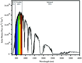 | ||
| Fig. 1 The AM 1.5 global solar spectrum. Reproduced with permission (Elsevier) from ref. 4 (AM = air mass). | ||
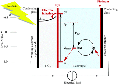
The Grätzel n-type DSC5,6 was developed in the early 1990s and converts solar energy to electrical energy; Fig. 2 presents a schematic diagram showing the working principle of the cell. Grätzel's landmark discovery was to use sintered nanoparticles of semiconductor,7 thereby providing a huge surface area that can be functionalized with dye, but at the same time keeping the device small in size and allowing electron transfer between particles. Nanoparticles of the semiconductor (most often, TiO2 in the form of anatase in an n-type DSC) are coated (e.g. by screen-printing) onto a transparent conducting oxide glass electrode usually fluorine-doped tin oxide, FTO, or indium-doped tin oxide, ITO. The surface is then functionalized with a dye.
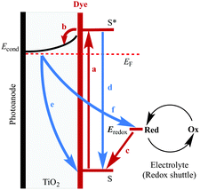
The absorption of visible light results in excitation of an electron from the highest occupied molecular orbital (HOMO) into the lowest unoccupied molecular orbital (LUMO) of the dye to give the excited state. This is followed by electron transfer (injection) into the conduction band of the semiconductor (Fig. 2) which formally oxidizes the dye. To regenerate the ground state of the dye, an electron is transferred from the electrolyte (which comprises a redox couple) to the dye. This, in turn, oxidizes the electrolyte, and the electrical circuit is completed by catalytic reduction of the electrolyte at a platinized counter-electrode. The electrolyte (also called a redox shuttle) is a critical component of the DSC.8,9 The potential of the redox couple is defined by the energy level Eredox in Fig. 2, and the difference in the potentials of the redox couple and the dye drives the electron transfer from electrolyte to dye. In the discussion that follows, it is important to note that electron-transfer processes can be discussed in terms of electrons or holes. For example, the electrolyte can be considered to be an electron or a hole transporter depending whether the principal charge propagation mechanism is reductive or oxidative. In conventional Grätzel n-type DSCs, the sensitizers are ruthenium(II) complexes and the electrolyte comprises the I−/I3− redox couple (eqn (1)).
| I3− + 2e− ⇌ 3I− | (1) |
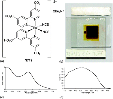
Ideally, dyes should absorb light over the whole of the solar spectrum, with as high an extinction coefficient as possible at any given wavelength. For a dye absorbing under an air mass 1.5 global spectrum (Fig. 1) at 100 mW cm−2 and with an absorption threshold of 900 nm (i.e. the longest wavelength at which the dyes absorbs light), the maximum photocurrent density theoretically possible is 33 mA cm−2.5 The wide spectral response of ruthenium dyes such as N3, black dye and N7195 and their high photon-to-current efficiency makes these the state-of-the-art dyes. N719 is typically used as a reference dye in the work overviewed in this article. Fig. 4 illustrates the structure of N719; its deep red colour (Fig. 4b) gives rise to the broad metal-to-ligand charge transfer (MLCT) band (λmax = 542 nm) which is shown in Fig. 4c in the solid-state absorption spectrum of N719 anchored to an FTO/TiO2 electrode.
When a DSC is irradiated, the voltage produced (the open-circuit voltage, VOC) is the difference between the redox potential of the electrolyte (Eredox) and the Fermi level (EF) of the semiconductor (Fig. 2). The overall power conversion efficiency (η, in %) of the DSC is given by eqn (2) where JSC is the short-circuit current density (in mA cm−2), FF is the fill factor of the cell (in %) and PIN is the total solar power incident on the DSC (100 mW cm−2 for air mass 1.5, see Fig. 1). More detailed discussion of these parameters can be found elsewhere.6,8 We will mostly be concerned with values of η, JSC and VOC (eqn (2)), and how these can be improved for copper-containing DSCs.
 | (2) |
A word of a warning before we go on to discuss the development of copper-containing DSCs. Since 1993, there has been an exponential growth in the number of papers reporting the performances of DSCs, and the reader must develop a critical eye when comparing data from different literature reports. In a recent review,14 we highlighted the varying standards of reporting DSC data, and the too common lack of an internal reference such as N719 and use of duplicate DSCs to validate data. The problems have also been brought home by Snaith in an aptly entitled commentary ‘The perils of solar cell efficiency measurements’.15 We shall refer later to ‘masked’ DSCs; masking is a means of ensuring that the photocurrent produced by the cell is not overestimated,16 but it is a technique that is not universally applied in research laboratories.15
Why choose copper?
If the DSC technology is established and improving in efficiency, why fix it, if it ain't broke? Dye sensitizers such as N719 are complexes containing ruthenium, which is one of the rarest (crustal abundance 0.000037)17 and most expensive (US$1447 per kilogram, 29 June 2015)18 metals. In considering the development of sustainable technologies, it is relevant to ask whether ruthenium compounds can be replaced by complexes of more abundant metals. The metal that has attracted most attention is copper which is more abundant than ruthenium (crustal abundance 27 ppm),17 cheaper (US $5.8 per kilogram, 4 July 2015),19 and forms bis(diimine) complexes that possess photophysical properties which resemble those of ruthenium(II) diimine complexes.20,21Both [RuL3]2+ and [CuL2]+ (L = diimine ligand) are typically orange with absorptions between 400 and 550 nm, although the absorption coefficients of the copper complexes are usually lower (≈5000 M−1 cm−1) than those of the ruthenium species (≈15![[thin space (1/6-em)]](https://www.rsc.org/images/entities/char_2009.gif) 000 M−1 cm−1). The excited states in both cases are primarily MLCT, arising from the excitation of an electron from the metal d-manifold to an antibonding π* orbital of the ligand. The MLCT excited state has rather different characteristics in ruthenium(II) and copper(I) complexes. In the case of ruthenium compounds, there is relatively little change in the equilibrium geometry between the ground and excited states. In contrast, the formal description of the copper MLCT state is a d9 copper(II) species which is expected to undergo Jahn–Teller distortion if the lifetime is long enough. Typically, copper(I) complexes are tetrahedral whereas copper(II) species favour a square-planar arrangement and the flattening in the MLCT state leads to extensive solvent interactions with consequent shortening of the excited state lifetime. Substituents in the ligands lead to significant distortions from the idealized tetrahedral geometry in the ground state and this in turn can dramatically influence the excited state characteristics and lifetimes.22
000 M−1 cm−1). The excited states in both cases are primarily MLCT, arising from the excitation of an electron from the metal d-manifold to an antibonding π* orbital of the ligand. The MLCT excited state has rather different characteristics in ruthenium(II) and copper(I) complexes. In the case of ruthenium compounds, there is relatively little change in the equilibrium geometry between the ground and excited states. In contrast, the formal description of the copper MLCT state is a d9 copper(II) species which is expected to undergo Jahn–Teller distortion if the lifetime is long enough. Typically, copper(I) complexes are tetrahedral whereas copper(II) species favour a square-planar arrangement and the flattening in the MLCT state leads to extensive solvent interactions with consequent shortening of the excited state lifetime. Substituents in the ligands lead to significant distortions from the idealized tetrahedral geometry in the ground state and this in turn can dramatically influence the excited state characteristics and lifetimes.22
Copper(I) complexes are labile and exchange ligands rapidly, whereas with ruthenium(II) complexes, coordinated ligands “stay stuck”. This last observation prevented the early investigation of copper(I) complexes as dye sensitizers although the search for less labile compounds was linked with the early development of supramolecular chemistry by Lehn and Sauvage in Strasbourg. The observation that copper(I) complexes are labile in solution does not necessarily mean that surface-bound species with anchored ligands will be equally labile. A second feature is the ease of oxidation of copper(I) complexes to copper(II), which is dramatically reduced by the use of ligands bearing substituents which envelop the metal and hinder rearrangement to the preferred copper(II) geometries.23 With these short comments, we now proceed to consider the structural requirements for copper(I) dyes for DSCs.
Homoleptic copper(I) dyes
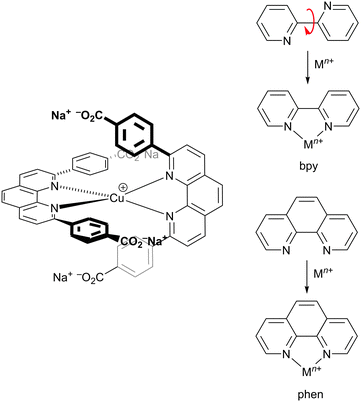
The potential for combining copper(I) dyes with wide band-gap semiconducting metal oxides (e.g. TiO2 or ZnO) for light-harvesting and photoconversion was first demonstrated by Sauvage and coworkers.24Scheme 1 (left) shows the structure of the dye designed by Sauvage and exemplifies three key features of copper(I) dyes: (i) a bis(diimine) metal-binding domain which typically comprises 2,2′-bipyridine (bpy) and/or 1,10-phenanthroline (phen) units; (ii) substituents in the positions next to the N,N′-coordination site to hinder flattening of the tetrahedral copper(I) coordination sphere, militating against irreversible oxidation to copper(II); (iii) peripheral carboxylate groups which anchor the dye to the semiconductor. As discussed below, these three characteristics have been modified over the past decade to improve the performances of bis(diimine)copper(I) dyes in DSCs. Derivatives of the diimines bpy and phen are popular as ligands in copper(I) sensitizers, but an important difference is the change of conformation that bpy must undergo as it forms a metal chelate. In contrast, phen is preorganized for coordination (Scheme 1, right). This results in complexes derived from [Cu(phen)2]+ having stability constants around one to two log![[thin space (1/6-em)]](https://www.rsc.org/images/entities/char_2009.gif) K units greater than analogous complexes with bpy.
K units greater than analogous complexes with bpy.
Despite growing interest in the photophysical behaviour of bis(diimine)copper(I) complexes,21,25 little progress in their use in DSCs was made26 following Sauvage's 1994 report until our own discovery in 2008 that dyes [Cu(1)2]+ and [Cu(2)2]+ (Scheme 2) anchored to mesoporous TiO2 achieved photoconversion efficiencies of 1.9 and 2.3% relative to 9.7% recorded for the reference dye N719 (Fig. 4).27 The orange-red complexes [Cu(1)2][PF6] and [Cu(2)2][PF6] were prepared by reaction of [Cu(NCMe)4][PF6] with two equivalents of ligands 1 or 2 (Scheme 2) and this method is a typical procedure to prepare the homoleptic copper(I) complexes discussed in this section. We look more closely at the relationships between solution absorption spectra of dyes, absorption characteristics of surface-bound dyes and EQE spectra later. For now, it is sufficient to note that the extended conjugation on going from 1 to 2 increases the spectral response of [Cu(2)2]+ with respect to [Cu(1)2]+ and leads to a higher value of EQEmax (50.1% for an electrode-functionalized with [Cu(2)2]+versus 38.6% for [Cu(1)2]+, both with λmax = 470 nm). Extending light-harvesting into the red is a major objective for improving copper dyes, and this point should be kept in mind as we assess the progress that has been made in the last few years.
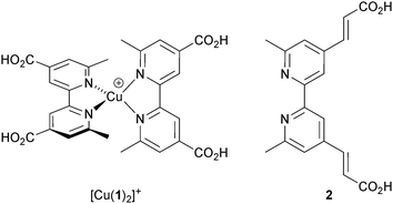 | ||
| Scheme 2 The simple homoleptic dyes [Cu(1)2]+ and [Cu(2)2]+ initiated our explorations of copper(I)-containing DSCs. | ||
The improvement of the performance of DSCs containing homoleptic copper(I) dyes is hampered by the fact that their symmetrical nature prevents the incorporation of a ‘push–pull’ system (Fig. 5) to facilitate electron transfer across the dye. Despite structural tuning of the diimine domain in the ligands, L, in homoleptic [CuL2]+ complexes, no notable improvements in their performances in DSCs have been achieved without changes to the electrolyte (see later section).
Despite their limitations, homoleptic [CuL2]+ dyes continue to be valuable models in theoretical investigations for gaining insight into the electronic structure of copper(I) dyes.28
‘Surfaces-as-ligands, surfaces-as-complexes’ approach to heteroleptic copper(I) dyes
In this section, all studies with copper(I) dyes have been carried out using I−/I3− electrolytes. In order to improve the performances of copper(I) sensitizers, the challenge is to develop routes to stable heteroleptic dyes in which one ligand (Lanchor) carries a group appropriate for anchoring29 the dye to the semiconductor and the second ligand (Lancillary) can be electronically and structurally tuned to enhance electron transfer from electrolyte to dye. Heteroleptic complexes of the type [Cu(Lanchor)(Lancillary)]+ tend to be difficult to isolate because they usually equilibrate in solution giving statistical mixtures30 according to eqn (3).| 2[Cu(Lanchor)(Lancillary)]+ ⇌ [Cu(Lanchor)2]+ + [Cu(Lancillary)2]+ | (3) |
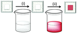
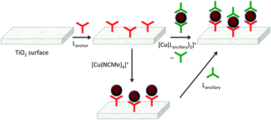
The first approach to access heteroleptic dyes is our ‘surfaces-as-ligands, surfaces-as-complexes’ approach,30 summarized in Fig. 6 and 7, and applied by others to assemble heteroleptic copper(I) dyes.31,32 Photoanodes (i.e. conducting glass such as FTO with an active layer of TiO2, Fig. 2 and 6, left) are first soaked in a solution of Lanchor (typically for one day) and then dried. The functionalized surface acts as a ligand (‘surface-as-ligand’) and soaking this electrode in a solution of a homoleptic complex [Cu(Lancillary)2]+, a mixture of [Cu(NCMe)4]+ and Lancillary, or sequentially in baths of [Cu(NCMe)4]+ and then Lancillary, results in ligand exchange and the formation of the surface-anchored dye (Fig. 7). Copper(I) dyes with bpy of phen chelating ligands are characteristically orange or red due to an MLCT band around 450–500 nm. The colour change shown in the second step in Fig. 6 (which can be quantified by solid-state absorption spectroscopy) is consistent with the formation of a [Cu(diimine)2]+ chromophore.
The use of either [Cu(Lancillary)2]+ or a mixture of [Cu(NCMe)4]+ and Lancillary in the assembly of photoactive dyes on TiO2 both have their advantages. Isolating the homoleptic complex permits investigations of absorption spectroscopic and electrochemical properties, both of which are critical for sensitizers in DSCs. However, as Fig. 7 illustrates, a consequence of ligand exchange involving [Cu(Lancillary)2]+ is the waste of one equivalent of the ancillary ligand. The lower route in Fig. 7 is more atom-economical in that the copper(I) solvento complex [Cu(NCMe)4]+ and Lancillary are present in the desired 1![[thin space (1/6-em)]](https://www.rsc.org/images/entities/char_2009.gif) :
:![[thin space (1/6-em)]](https://www.rsc.org/images/entities/char_2009.gif) 1 copper
1 copper![[thin space (1/6-em)]](https://www.rsc.org/images/entities/char_2009.gif) :
:![[thin space (1/6-em)]](https://www.rsc.org/images/entities/char_2009.gif) ligand ratio. Our experience is that both routes in Fig. 7 lead to DSCs which perform similarly,33 but in the second route, use of a mixture of [Cu(NCMe)4]+ and Lancillary is preferred over sequential dye-baths of [Cu(NCMe)4]+ and Lancillary.
ligand ratio. Our experience is that both routes in Fig. 7 lead to DSCs which perform similarly,33 but in the second route, use of a mixture of [Cu(NCMe)4]+ and Lancillary is preferred over sequential dye-baths of [Cu(NCMe)4]+ and Lancillary.
On-surface copper(I) dye assembly is an efficient procedure for screening different combinations of anchoring and ancillary ligands. Its first success was to establish that anchoring through phosphonic acids (or phosphonates since the protonation state of the anchor is ambiguous) leads to enhanced conversion efficiencies with respect to dyes bearing carboxylic acid anchors.34 This is consistent with Grätzel's observations for ruthenium dyes,35 despite the fact that state-of-the-art ruthenium dyes anchor to TiO2 through carboxylate groups. The presence of an arene spacer between bpy and anchoring groups (Scheme 3) improves the efficiency of the dye.36
Among the factors that contribute to the poorer performances of copper(I) dyes compared to state-of-the-art ruthenium(II) or organic dyes are (i) the smaller range of wavelengths over which copper complexes absorb light compared to ruthenium dyes, and (ii) the lower values of JSC which contribute to lower overall efficiencies; remember that JSC values are evaluated in conjunction with EQE spectra. Both of these factors are addressed in the structural modifications discussed below.
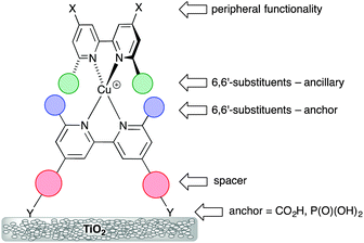
Scheme 3 illustrates the structural features that are most easily modified in a sensitizer while retaining a {Cu(bpy)2}+ core. As stated above, substituents adjacent to the metal-binding sites (6,6′-functionalized bpy ligands) are essential for preventing the irreversible oxidation of copper(I) to copper(II). Methyl groups are sufficient, but aryl substituents have an advantage in that they cause flattening of the tetrahedral coordination sphere, leading to two (rather than one) MLCT bands, both in {Cu(bpy)2}+ and {Cu(phen)2}+ based complexes,14,36 thereby widening the energy range of light absorbance by the dye. The flattening is caused by face-to-face π-stacking interactions involving the phenyl group of one ligand and one pyridine ring of the second ligand36 (Fig. 8a). Such π–π interactions are widespread in metal complexes containing polypyridine ligands,37 and not only tune absorption and emission properties, but can also lead to increased lifetimes of excited states. As described in the introduction, excitation of a copper(I) dye and injection of an electron into the conduction band of the semiconductor oxidizes the dye. Since the excited state dye is formally a copper(II) species, the coordination sphere tends towards being square planar and is open to attack by coordinating solvents such as MeCN, leading to quenching of the excited state. Since the 6,6′-diphenyl substitution pattern already induces flattening of the copper(I) coordination sphere (Fig. 8a), only a minor photoinduced structural change occurs upon excitation and the π-stacking interactions protect the copper centre from solvent attack, thereby increasing the MLCT excited state lifetime when the complex is in a coordinating solvent.28
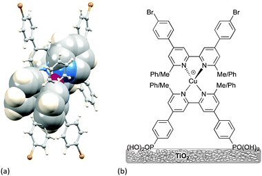 | ||
| Fig. 8 (a) Flattening of the tetrahedral geometry around the Cu atom caused by π-stacking of two pairs of phenyl–pyridine rings; the structure shown was crystallographically determined for a homoleptic complex containing two 4,4′-bis(4-bromophenyl)-6,6′-diphenyl-2,2′-bipyridine ligands.36 The rings involved in π–π interactions are shown in space-filling representations. (b) Structures of the dyes used to demonstrate the effects of having 6,6′-Me2bpy or 6,6′-Ph2bpy copper-binding domains in anchoring versus ancillary ligands. | ||
The effects of having 6,6′-Me2bpy or 6,6′-Ph2bpy copper-binding domains in anchoring versus ancillary ligands have been demonstrated using four on-surface assembled dyes, the structures of which are summarized in Fig. 8b. Using the nomenclature in Scheme 3, the dyes have the same peripheral unit, the same phosphonic acid anchoring unit with phenylene spacer, and either a {Cu(6,6′-Me2bpy)2}+, {Cu(6,6′-Me2bpy)(6,6′-Ph2bpy)}+ or {Cu(6,6′-Ph2bpy)2}+ coordination environment; for {Cu(6,6′-Me2bpy)(6,6′-Ph2bpy)}+, the phenyl (or methyl) substituents are in either the anchoring or ancillary ligand, respectively. The solid-state absorption spectra (Fig. 9a) of the four dyes reveal enhanced absorption towards the red-end of the spectrum (longer wavelengths) when phenyl substituents are present. When the electrodes are incorporated into DSCs, the EQE spectra (Fig. 9b) confirm electron injection towards the red-end of the spectrum for dyes containing the phenyl substituents in the anchoring ligand (blue and black curves in Fig. 9b). However, values of EQEmax are far higher for the dyes containing methyl substituents in Lanchor. Thus, despite the wider spectral response of the dyes with a 6,6′-diphenyl-substitution pattern, the EQE data reveal that conversion of absorbed light into electrical current is low, and results in poorer overall efficiencies.30
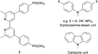 | ||
| Scheme 4 Structure of anchoring ligand 3, and structures of typical hole transporting domains, used to functionalize the periphery (see Scheme 3) of dyes. | ||
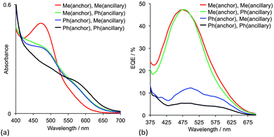 | ||
| Fig. 9 (a) Solid-state absorption spectra and (b) EQE spectra of TiO2 electrodes with adsorbed dyes containing 6,6′-Me2bpy or 6,6′-Ph2bpy copper-binding domains.30 The ligands are shown in Fig. 8b. | ||
In the remaining part of this section, we focus on the optimization of DSC performance using dyes with {Cu(bpy)2} cores and bis(phosphonic acid) 3 (Scheme 4) as Lanchor. Ligand 3 is our anchor of choice in copper(I) dyes, although the field is open to trials of alternative anchoring groups.29 All the results discussed in the remainder of this section refer to masked DSCs, and duplicate DSCs have been used in our investigations to validate the data (see the Introduction).
With a 6,6′-dimethyl-substituted anchoring ligand, one can question the need for a 6,6′-substituted ancillary ligand. Is one set of blocking groups sufficient to stabilize the heteroleptic dye? This has been addressed by comparing the performances of DSCs containing the on-surface assembled dyes [Cu(3)(4)]+, [Cu(3)(5)]+ and [Cu(3)(6)]+ in which 4, 5 and 6 contain bpy, 6-Mebpy and 6,6′-Me2bpy copper-binding domains, respectively (Scheme 5). The ditopic nature of these ligands permits the on-surface dyes to be extended through coordination to copper(I) or ruthenium(II).38Fig. 10 shows J–V curves and EQE spectra of DSCs containing [Cu(3)(4)]+, [Cu(3)(5)]+ and [Cu(3)(6)]+. The respective values of JSC = 3.13, 4.18 and 5.20 mA cm−2 (Fig. 10a) compare with 15.7 mA cm−2 for N719; values of VOC of 524, 548 and 566 mV compare to 628 mV for N719. All three copper dyes exhibit maximum EQE values at a wavelength (λmax) of ≈480 nm, and EQEmax increases from 24.7% for [Cu(3)(4)]+ to 34.0% for [Cu(3)(6)]+ (Fig. 10b). The photoconversion efficiencies are 1.16, 1.69 and 2.16% for DSCs sensitized with [Cu(3)(4)]+, [Cu(3)(5)]+ and [Cu(3)(6)]+, respectively; taken relative to N719 (measured η = 7.17%, relative efficiency set to 100%), the best of this set of DSCs achieves 30.1%.38 The trend observed on going from a bpy to 6-Mebpy to 6,6′-Me2bpy domain in the ancillary ligand is supported by the performances of DSCs containing [Cu(Lanchor)(Lancillary)]+ dyes with the model ancillary ligands bpy, 6-Mebpy and 6,6′-Me2bpy and the 6,6′-diphenyl-substituted analogue of anchor 3; in this case, the dye having no 6,6′-substituents in Lanchor performs significantly worse than those with one or two substituents.30 This last investigation was devised only to observe trends in values, and, as expected, all performances are relatively low because Lancillary is not optimized through structural/electronic design.
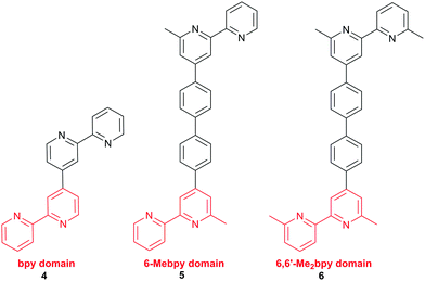 | ||
| Scheme 5 Ancillary ligands used to combine with anchor 3 (Scheme 4) in the dyes [Cu(3)(4)]+, [Cu(3)(5)]+ and [Cu(3)(6)]+. The copper-binding domain is shown in red. | ||
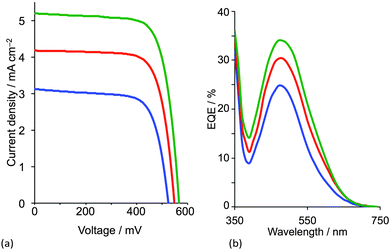 | ||
| Fig. 10 (a) J–V curves and (b) EQE spectra of DSCs containing [Cu(3)(4)]+ (blue), [Cu(3)(5)]+ (red) and [Cu(3)(6)]+ (green).38 | ||
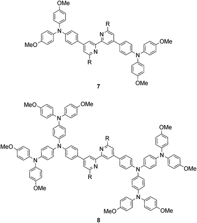
Common strategies for improving light absorption are to extend π-conjugation within the dye and to design ‘push–pull’ dyes (Fig. 5). The aim of introducing suitable donor groups on the periphery (Scheme 4) of the sensitizer is to enhance electron transfer from electrolyte to oxidized (excited state) dye and to minimize recombination (Fig. 3) of the electron–hole pair generated after electron injection. Critically, there should be good spatial separation between the injected electron and the hole. In a well-designed heteroleptic [Cu(Lanchor)(Lancillary)]+ dye, the lowest unoccupied molecular orbital (LUMO) should reside on Lancillary so that the electron is localized on this domain in the excited state (ideal for injection into the semiconductor). In contrast, the HOMO of the excited state should be localized on the ancillary ligand. So-called ‘hole-transporting’ domains often incorporate diphenylamine or carbazole units (Scheme 4) and are commonly employed in organic dyes.39 Two series of bpy-based ligands (7 and 8) incorporating first- and second-generation hole-transporting dendrons in the 4- and 4′-positions (Scheme 6) have been used as ancillary ligands in [Cu(3)(7)]+ and [Cu(3)(8)]+ dyes assembled in a stepwise manner on FTO/TiO2 photoanodes.40 In addition to looking at the effects of extending the hole-transporting domain, 7 and 8 feature 6,6′-substituents with different steric demands (Scheme 6, caption). In general, bulky substituents lead to lower DSC performances, but the picture is not simple because the trends depend upon the solvent in the dye-bath during ligand exchange (step (ii) in Fig. 6) as the dye is assembled.40 The results for DSCs containing [Cu(3)(7methyl)]+ and [Cu(3)(8methyl)]+ (7methyl and 8methyl = 6,6′-dimethyl-substituted 7 and 8) demonstrate improved values of JSC on going from first- to second-generation ancillary ligands, e.g. 6.00 for [Cu(3)(7methyl)]+ and 6.46 mA cm−2 for [Cu(3)(8methyl)]+. However, these values are less than half that of the N719 reference cell measured in the same study (≈16.5 mA cm−2), and corresponding values of VOC for [Cu(3)(7methyl)]+ and [Cu(3)(8methyl)]+ (510 and 515 mV) are also lower than for N719 (≈640 mV). Overall, DSCs containing the copper dyes show relative performances with respect to N719 of around 30% (in real terms, η = 2.15–2.26% versus 6.90–7.32% for N719).
The improvement in photoconversion efficiencies by introducing elaborate hole-transporting dendrons is not as pronounced as one might expect. A modelled structure of the second-generation dye [Cu(3)(8methyl)]+ is shown in Fig. 11a. The large number of arene rings on the periphery of the second-generation dendron encourage aggregation of dye molecules through π-stacking interactions.37 Dye aggregation on the semiconductor surface is detrimental to performance since it enables rapid non-radiative decay pathways of the excited state. Dye aggregation is minimized by adding a co-adsorbant such as chenodeoxycholic acid (cheno, Fig. 11b). Co-adsorbants are designed to anchor to the surface and to spatially separate the dye molecules, i.e. reduce the dye loading on the surface. The addition of cheno to [Cu(3)(8methyl)]+ in DSCs improves performance, with a significant increase in both JSC and VOC. The performance parameters depend on the solvent in the dye-bath (CH2Cl2 or acetone).33
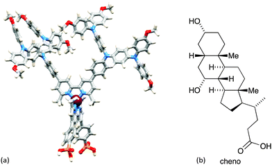 | ||
| Fig. 11 (a) Modelled structure of [Cu(3)(8methyl)]+ (molecular mechanics level, Spartan 14 v. 1.1.8, Wavefunction, Inc.). (b) Structure of co-adsorbant chenodeoxycholic acid (cheno). | ||
While the addition of cheno enhances DSC performance immediately after the solar cells are fabricated, a time-dependent reorganization of the dye molecules may also result in enhanced photoconversion. This ageing (or ripening) process has been observed for many copper(I) dyes, and is also known for ruthenium(II) sensitizers for which it is rationalized in terms of disaggregation.41 Sterically demanding dye molecules suffer most from this initiation period before they reach maximum performance. Sterically unencumbered dyes such as [Cu(3)(6,6′-Me2bpy)]+ show no evidence for reorganization on a TiO2 surface over time.33 Controlling the loading of dyes on the TiO2 surface is key to attaining optimal DSC performance immediately after the DSCs are constructed. This has been demonstrated by varying the concentration of the homoleptic complex [Cu(7methyl)2]+ in the dye-bath during the on-surface assembly (Fig. 6) of [Cu(3)(7methyl)]+. Fig. 12a shows how the overall efficiency of the DSCs changes over a period of 3 days; day 0 corresponds to the day on which the DSC was made. The most dilute dye-bath leads immediately to optimal performance (red line in Fig. 12a), whereas with more concentrated dye-baths, the DSC has to ripen before optimal performance is attained. Trends in efficiencies (Fig. 12a) correlate well with trends in JSC values (Fig. 12b). On the other hand, the highest values of VOC are exhibited by the DSCs made using the most concentrated dye-bath and values of VOC vary little over time.42
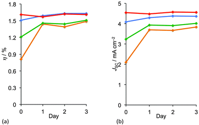 | ||
| Fig. 12 Changes over time in (a) overall photoconversion efficiency (η) and (b) short-circuit current density (JSC) for DCs sensitized with [Cu(3)(7methyl)]+, as a function of the concentration of [Cu(7methyl)2]+ (MeCN solution) in the dye-bath (see Fig. 5). Concentrations: 2.0 mM (orange), 1.0 mM (green), 0.5 mM (blue), 0.1 mM (red).42 | ||
The preparation of organic ligands with elaborate hole-transporting domains requires significant synthetic effort, and this must be justified in terms of DSC performance. Fig. 8 showed dyes in which the peripheral functionality was a simple bromo group. This functionality is often introduced as an active site for further derivatization. In terms of the ‘push–pull’ design shown in Fig. 5, halo-substituents are not obvious candidates in sensitizers, but DSCs containing dyes with peripheral halo-substituents function surprisingly well.43 The series of dyes [Cu(3)(9halo)]+ shown in Fig. 13a all perform well in DSCs, with values of a maximum JSC value of 7.42 mA cm−2 for [Cu(3)(9iodo)]+ compared to 16.21 mA cm−2 for an N719 reference DSC. Values of VOC reach around 600 mV (662–692 mV for N719). On the day the DSCs were constructed, the trend for the photoconversion efficiencies for [Cu(3)(9halo)]+ follows the order I > F ≈ Br > Cl. As the DSCs age over 7 days, ripening effects are observed but the best performing DSCs remain those with the iodo-functionalized dye. At the time of publication, this efficiency was the highest for a masked DSC with a copper(I) sensitizer with η = 3.16% for [Cu(3)(9iodo)]+ compared to 7.63% for a reference DSc containing N719. Compared to the other halo-functionalized dyes, [Cu(3)(9iodo)]+ exhibits an extended spectral response to longer wavelength and enhanced electron injection. Fig. 13b compares the EQE spectra of [Cu(3)(9iodo)]+ and [Cu(3)(9bromo)]+ after the DSCs have aged for 3 days. The values of EQEmax = 51.4% (iodo) and 46.2% (bromo) compare with 75.3% for N719. While these are extremely promising, it is clear from Fig. 13b that the copper(I) dyes lack efficient photon-to-current conversion at wavelengths higher than 550 nm. Nonetheless, after 7 days, DSCs sensitized with [Cu(3)(9iodo)]+ perform ≈36% as well as those with N719 (set at 100%). The results of DFT calculations indicate that the enhanced performance of [Cu(3)(9iodo)]+ with respect to the fluoro, chloro and bromo analogues may arise from better electron transfer over the halogen of the aryl substituent from the reduced electrolyte.
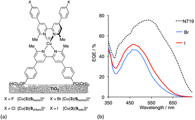 | ||
| Fig. 13 (a) Structures of halo-functionalized sensitizers [Cu(3)(9halo)]+. (b) EQE spectra of DSCs with [Cu(3)(9bromo)]+ and [Cu(3)(9iodo)]+ compared to a reference DSC with N719.43 | ||
The advantageous effects of fluoro-substituted ancillary ligands have been demonstrated in a number of organic and ruthenium dyes, and their presence may hinder charge recombination processes.44 Encouraged by the performance of dyes containing ancillary ligands 9halo, we adopted a strategy of combining the need for 6,6′-substituents in the bpy domain with the incorporation of halo-functionalities. Scheme 7 shows the ancillary ligands used in a comparative study of the performances of DSCs containing the heteroleptic dyes [Cu(3)(6,6′-Me2bpy)]+, [Cu(3)(10)]+ and [Cu(3)(11)]+. The electron-withdrawing CF3 groups stabilize the copper(I) state, as shown by the significant shift to higher potential of the Cu+/Cu2+ redox couple (+0.44 to +0.72 V versus Fc/Fc+, Fc = ferrocene) on going from [Cu(6,6′-Me2bpy)2]+ to [Cu(11)2]+; remember that the solution properties of heteroleptic complexes are not easily measured because of the equilibration shown in eqn (3), but data for homoleptic analogues provide insight into the influence of substituents in both homo- and heteroleptic species. The sensitizers [Cu(3)(10)]+ and [Cu(3)(11)]+ show admirable photoconversion efficiencies of ≈30–34% relative to N719 set at 100%; this is a noteworthy improvement with respect to DSCs containing [Cu(3)(6,6′-Me2bpy)]+ (η ≈ 23–25% relative to 100% for N719).45 This has its origins in improved JSC values (up to 5.81 mA cm−2 compared to 12.82 mA cm−2 for N719). However, apart from the stabilization of the HOMO, it remains to be understood why introducing CF3 groups into the 6,6′-positions of the ancillary ligand has such a dramatic effect. DFT calculations show that the introduction of the CF3 groups has little influence on the HOMO and LUMO orbital compositions, but does influence orbital energies.
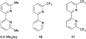 | ||
| Scheme 7 Structures of ligands used to investigate the effects of introducing CF3-groups into the 6,6′-positions in the ancillary ligand. | ||
The discovery that simple halo- or halogenated alkyl substituents in the ancillary ligand can lead to a significant enhancement in DSC performance leads us to re-evaluate the need for the design of elaborate ‘push–pull’ dyes. Both strategies are valuable, but for rapid development of copper(I) sensitizers, simpler synthetic strategies are the more appealing.
A final comment about the advantages of the ‘surfaces-as-ligands, surfaces-as-complexes’ approach: how to overcome the problem of bleached electrodes. In the presence of an I−/I3− electrolyte, some dyes ‘bleach’; this means that the sensitizer loses its colour and, therefore, its ability to absorb light in the visible range. Iodide ions in the electrolyte strip the ancillary ligand from the copper(I) centre. However, the dye can be regenerated by soaking the bleached electrode in a dye-bath containing [Cu(Lancillary)2]+. Fig. 14 summarizes the step-wise assembly of the dye, bleaching, and regeneration of the surface-anchored sensitizer.43 Recycling of bleached electrodes is an important step forward in terms of the use of environmentally-acceptable DSCs.
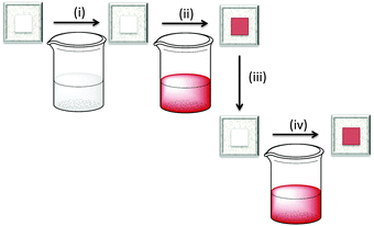 | ||
| Fig. 14 Stepwise, on-surface assembly of [Cu(Lanchor)(Lancillary)]+ dyes (steps (i) and (ii), see Fig. 6) followed by (iii) exposure to iodide ion which bleaches the electrode, and regeneration of the dye by (iv) soaking in a solution of [Cu(Lancillary)2]+ (a repeat of step (ii)). | ||
HETPHEN approach to heteroleptic copper(I) dyes
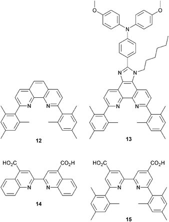
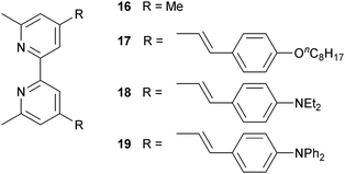
Since 2013, Odobel and coworkers have applied the HETPHEN approach to isolate heteroleptic bis(diimine)copper(I) complexes which can be adsorbed onto a semiconductor surface in a single dye-bath step. The crux of HETPHEN methodology46 is the use of 1,10-phenanthroline with highly sterically demanding mesityl substituents next to the N,N′-metal binding site (12, Scheme 8). Ligand 12 was extended to 13 (Scheme 8) to incorporate a diphenylamino hole-transporting domain; 13 also contains a long alkyl chain which helps to prevent dye aggregation and reduce charge recombination.47 In the heteroleptic dyes [Cu(14)(12)]+ and [Cu(14)(13)]+, the anchoring ligand 14 (Scheme 8) is based on 2,2′-biquinoline. The absorption spectra of copper(I)/2,2′-biquinoline complexes are significantly red-shifted with respect to those with 2,2′-bipyridine, and so the use of 14 should be advantageous for light harvesting above 550 nm.48 However, ligand 14 (in its deprotonated form) injects electrons poorly, and the performances of DSCs with [Cu(14)(12)]+ and [Cu(14)(13)]+ are poor (η = 0.49 and 0.22% with respect to 6.55% for N719). Upon DSC ageing, some enhancement of JSC is seen (1.61 to 2.17 mA cm−2 after 7 days for [Cu(14)(12)]+), but η remains low.46Despite these DSC performances, the synthetic methodology opened a new route to stable heteroleptic copper(I) complexes and later led to what is currently the record photon-to-current conversion efficiency for a copper dye. In 2014, Odobel and coworkers49 adapted the HETPHEN approach to bpy-containing complexes, placing mesityl substituents in the 6,6′-positions of Lanchor15 (Scheme 8). Anchor 15 was combined with ancillary ligands 16–19 (Scheme 9). The extended conjugation in 18 and 19, coupled with the design strategy of 15, led to two extremely efficient dyes, [Cu(15)(18)]+ and [Cu(15)(19)]+. EQE spectra for DSCs with these dyes confirm that the spectral range over which electron injection occurs extends to 740 nm (compare 770 nm for N719, Fig. 4d). Values of JSC were 7.51 and 6.70 mA cm−2 compared to 16.87 mA cm−2 for N719. With VOC values of 545 and 565 mV, this led to overall efficiencies of 2.93 and 2.77%. A remarkable improvement comes when the co-adsorbant cheno (see Fig. 11b and related discussion) is added. Both JSC and VOC are boosted, but it is the rise in JSC to 10.86 and 10.13 mA cm−2 for [Cu(15)(18)]+ and [Cu(15)(19)]+ that is most noteworthy, and this contributes to global efficiencies of 4.66% for [Cu(15)(18)]+, and 4.42% for [Cu(15)(19)]+. Breaking the 4% barrier confirmed that copper dyes have significant potential in DSCs.
The electrolyte
The majority of studies of copper(I) sensitizers use an I−/I3− electrolyte with compositions that have been optimized for ruthenium(II) dyes. Electrolyte optimization is an essential part of dealing with the kinetics of the competitive electron transfer processes in a DSC (Fig. 3). Additives (typically Li+ salts and 4-tert-butylpyridine) improve performance by tuning the TiO2 conduction band energy and reducing recombination. The benefits of one additive, guanidinium thiocyanate (GNCS) are controversial.50 A typical electrolyte composition as used in much of our own work is LiI (0.1 M), I2 (0.05 M), 1-methylbenzimidazole (0.5 M), 1-butyl-3-methylimidazolinium iodide (0.6 M) in 3-methoxypropionitrile; the solvent is chosen for its low volatility. Biagini and coworkers51 have demonstrated enhanced DSC performance for the dye [Cu(20)2]+ (Scheme 10) by removing the GCNS additive from an electrolyte comprising 1-butyl-3-methylimidazolinium iodide, LiI, I2, 4-tert-butylpyridine and GCNS in MeCN/valeronitrile. Values of JSC increase from 3.6 to 7.3 mA cm−2 and efficiencies from 1.3 to 3.0% (unmasked DSCs); the value of η = 3.0% drops to 2.5% upon masking the DSC. Despite this motivating study, systematic studies of I−/I3− electrolyte composition for copper dyes are still lacking.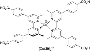 | ||
| Scheme 10 Structure of the dye [Cu(20)2]+ used by Biagini and coworkers to demonstrate the effects of I−/I3− electrolyte composition on DSC performance. | ||
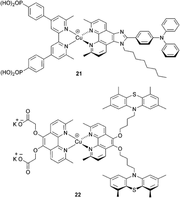
Although the I−/I3− redox shuttle is commonplace in DSCs, its disadvantages, including it corrosive properties, are well established.52,53 Alternative redox couples include Co2+/Co3+, often used in DSCs as [Co(bpy)3]2+/3+, [Co(phen)3]2+/3+ or derivatives thereof.52 The effectiveness of [Co(bpy)3]2+/3+ as an electrolyte with copper sensitizers was first shown for [Cu(3)(Lancillary)]+ (Scheme 11, 21) where Lancillary has similar design characteristics as 13 (see above). The performance parameters for DSCs with this dye are comparable using either I−/I3− or [Co(bpy)3]2+/3+; for the latter, an optimal JSC value of 5.05 mA cm−2 contributed to an overall DSC efficiency of 1.73% in masked cells.54 The potential for replacing I−/I3− by Co2+/Co3+ electrolytes has also been shown by Elliott, using [Co(4,4′-tBu2bpy)3]2+/3+ and the heteroleptic dye 22 (Scheme 11).32 The peripheral 10H-phenothiazine groups facilitate rapid reduction of copper(II) in the excited state dye, and this militates against kinetic trapping of Cu(II) by the 4-tbutylpyridine additive in the [Co(4,4′-tBu2bpy)3]2+/3+ electrolyte. This brings us full circle to the need for investigations of electrolytes composition and the effects that additives have on DSC performance. Optimization of electrolytes for copper(I) DSCs is essential if photoconversion efficiencies are to be further increased.
Conclusions
The outstanding values of global efficiencies of 4.66% for [Cu(16)(19)]+, and 4.42% for [Cu(16)(20)]+ reinforce the belief that future DSCs can utilize Earth-abundant metals rather than the very rarest of elements. Progress is slow, but steady optimization of all of the cell components is ongoing in laboratories world-wide. A major advantage of the copper-based cells is the potential to regenerate exhausted cells using solution processing as indicated in the section on bleaching.Abbreviations
| AM | Air mass |
| DSC | Dye-sensitized solar cell |
| EQE | External quantum efficiency |
| HOMO | Highest occupied molecular orbital |
| FF | Fill factor |
| J SC | Short-circuit current (or photocurrent) density |
| LUMO | Lowest unoccupied molecular orbital |
| MLCT | Metal-to-ligand charge transfer |
| V OC | Open circuit voltage |
| η | Overall photoconversion efficiency (global efficiency) |
Acknowledgements
We thank the Swiss National Science Foundation, the European Research Council (Advanced Grant 267816 LiLo) and the University of Basel for financial support for our work with DSCs incorporating earth-abundant metals. We acknowledge all of the members of our research group for their dedicated work, and in particular, Sebastian O. Fürer and Frederik J. Malzner for providing spectra and the photograph for Fig. 4.Notes and references
- BP Energy Outlook 2030, retrieved 04 July 2015, http://www.bp.com/content/dam/bp/pdf/statistical-review/BP_World_Energy_Outlook_booklet_2013.pdf.
- 2012 Key World Energy Statistics, retrieved 04 July 2015, http://www.iea.org/publications/freepublications/.
- V. Smil, Energy: A Beginner's Guide, Oneworld Publications, Oxford, 2006 Search PubMed.
- M. S. Lazorski and F. N. Castellano, Polyhedron, 2014, 82, 57 CrossRef CAS.
- M. Grätzel, Acc. Chem. Res., 2009, 42, 1788 CrossRef PubMed; M. Grätzel, Inorg. Chem., 2005, 44, 6841 CrossRef PubMed; M. Grätzel, J. Photochem. Photobiol., C, 2003, 4, 145 CrossRef and references therein.
- Dye Sensitized Solar Cells, ed. K. Kalyanasundaram, CRC Press, Boca Raton, 2010 Search PubMed.
- B. O’Regan and M. Grätzel, Nature, 1991, 353, 737 CrossRef.
- T. W. Hamann and J. W. Ondersma, Energy Environ. Sci., 2011, 4, 370 Search PubMed and references therein.
- J. Wu, Z. Lan, J. Lin, M. Huang, Y. Huang, L. Fan and G. Luo, Chem. Rev., 2015, 115, 2136 CrossRef CAS PubMed and references therein.
- A. J. Frank, N. Kopidakis and J. van de Lagemaat, Coord. Chem. Rev., 2004, 248, 1165 CrossRef CAS and references therein.
- J. W. Ondersma and T. W. Hamann, Coord. Chem. Rev., 2013, 257, 1533 CrossRef CAS and references therein.
- J. N. Clifford, E. Martínez-Ferrero and E. Palomares, J. Mater. Chem., 2012, 22, 12415 RSC and references therein.
- F. Fabregat-Santiago, J. Bisquert, G. Garcia-Belmonte, G. Boschloo and A. Hadfeldt, Sol. Energy Mater. Sol. Cells, 2005, 87, 117 CrossRef CAS.
- B. Bozic-Weber, E. C. Constable and C. E. Housecroft, Coord. Chem. Rev., 2013, 257, 3089 CrossRef CAS and references therein.
- H. J. Snaith, Nat. Photonics, 2012, 6, 337 CrossRef CAS and references therein.
- B. Bozic-Weber, S. Y. Brauchli, E. C. Constable, S. O. Fürer, C. E. Housecroft and I. A. Wright, Phys. Chem. Chem. Phys., 2013, 15, 4500 RSC.
- http://www.rsc.org/periodic-table/, retrieved 04 July 2015.
- http://https://www.quandl.com/collections/markets/rare-metals, retrieved 04 July 2015.
- http://www.lme.com/metals/non-ferrous/copper/, retrieved 04 July 2015.
- N. Armaroli, Chem. Soc. Rev., 2001, 30, 113 RSC.
- N. Armaroli, G. Accorsi, F. Cardinali and A. Listorti, Top. Curr. Chem., 2007, 280, 69 CrossRef CAS and references therein.
- M. W. Mara, K. A. Fransted and L. X. Chen, Coord. Chem. Rev., 2015, 282–283, 2 CrossRef CAS and references therein.
- V. Chaurin, E. C. Constable and C. E. Housecroft, New J. Chem., 2006, 30, 1740 RSC.
- N. Alonso-Vante, J.-F. Nierengarten and J.-P. Sauvage, J. Chem. Soc., Dalton Trans., 1994, 1649 RSC.
- A. Lavie-Cambot, M. Cantuel, Y. Leydet, G. Jonusauskas, D. M. Bassani and N. D. McClenaghan, Coord. Chem. Rev., 2008, 252, 2572 CrossRef CAS.
- S. Sakaki, T. Kuroki and T. Hamada, J. Chem. Soc., Dalton Trans., 2002, 840 RSC.
- T. Bessho, E. C. Constable, M. Graetzel, A. Hernandez Redondo, C. E. Housecroft, W. Kylberg, Md. K. Nazeeruddin, M. Neuburger and S. Schaffner, Chem. Commun., 2008, 3717 RSC.
- See for example: M. W. Mara, N. E. Jackson, J. Huang, A. B. Stickrath, X. Zhang, N. A. Gothard, M. A. Ratner and L. X. Chen, J. Phys. Chem. B, 2013, 117, 1921 CrossRef CAS PubMed.
- L. Zheng and J. M. Cole, ACS Appl. Mater. Interfaces, 2015, 7, 3427 Search PubMed and references therein.
- S. Y. Brauchli, F. J. Malzner, E. C. Constable and C. E. Housecroft, RSC Adv., 2015, 5, 48516 RSC.
- T. E. Hewat, L. J. Yellowlees and N. Robertson, Dalton Trans., 2014, 43, 4127 RSC.
- L. N. Ashbrook and C. M. Elliott, J. Phys. Chem. C, 2013, 117, 3853 CrossRef CAS.
- S. Y. Brauchli, F. J. Malzner, E. C. Constable and C. E. Housecroft, RSC Adv., 2014, 4, 62728 RSC.
- B. Bozic-Weber, E. C. Constable, C. E. Housecroft, P. Kopecky, M. Neuburger and J. A. Zampese, Dalton Trans., 2011, 40, 12584 RSC.
- P. Péchy, F. P. Rotzinger, Md. K. Nazeeruddin, O. Kohle, S. M. Zakeeruddin, R. Humphry-Baker and M. Grätzel, J. Chem. Soc., Chem. Commun., 1995, 65 RSC.
- B. Bozic-Weber, S. Y. Brauchli, E. C. Constable, S. O. Fürer, C. E. Housecroft, F. J. Malzner, I. A. Wright and J. A. Zampese, Dalton Trans., 2013, 42, 12293 RSC.
- C. Janiak, J. Chem. Soc., Dalton Trans., 2000, 3885 RSC.
- E. Schönhofer, B. Bozic-Weber, C. J. Martin, E. C. Constable, C. E. Housecroft and J. A. Zampese, Dyes Pigm., 2015, 115, 154 CrossRef.
- A. Mishra, M. K. R. Fischer and P. Bäuerle, Angew. Chem., Int. Ed., 2009, 48, 2474 CrossRef CAS PubMed.
- S. Y. Brauchli, B. Bozic-Weber, E. C. Constable, N. Hostettler, C. E. Housecroft and J. A. Zampese, RSC Adv., 2014, 4, 34801 RSC.
- See for example: B. Wenger, M. Grätzel and J.-E. Moser, J. Am. Chem. Soc., 2005, 127, 12150 CrossRef CAS PubMed.
- S. Y. Brauchli, E. C. Constable and C. E. Housecroft, Dyes Pigm., 2015, 113, 447 CrossRef CAS.
- S. Y. Brauchli, F. J. Malzner, E. C. Constable, C. E. Housecroft and M. Neuburger, RSC Adv., 2014, 4, 48712 RSC and references therein.
- See for example: G. Marzani, J. Durantini, D. Minudri, M. Gervaldo, L. Otero, F. Fungo, G. Pozzi, M. Cavazzini, S. Orlandi and S. Quici, J. Phys. Chem. C, 2012, 116, 21190 CrossRef.
- F. Brunner, M. Klein, S. Keller, C. D. Morris, A. Prescimone, E. C. Constable and C. E. Housecroft, RSC Adv., 2015, 5, 58694 RSC.
- M. Sandroni, M. Kayanuma, A. Planchat, N. Szuwarski, E. Blart, Y. Pellegrin, C. Daniel, M. Boujtita and F. Odobel, Dalton Trans., 2013, 42, 10818 RSC and references therein.
- K. Omata, S. Kuwahara, K. Katayama, S. Qing, T. Toyoda, K.-M. Lee and C.-G. Wu, Phys. Chem. Chem. Phys., 2015, 17, 10170 RSC and references therein.
- See for example: K. A. Wills, H. J. Mandujano-Ramírez, G. Merino, D. Mattia, T. Hewat, N. Robertson, G. Oskam, M. D. Jones, S. E. Lewis and P. J. Cameron, RSC Adv., 2013, 3, 23361 RSC.
- M. Sandroni, L. Favereau, A. Planchat, H. Akdas-Kilig, N. Szuwarski, Y. Pellegrin, E. Blart, H. Le Bozec, M. Boujtita and F. Odobel, J. Mater. Chem. A, 2014, 2, 9944 RSC.
- F. Bella, A. Sacco, D. Pugliese, M. Laurenti and S. Bianco, J. Power Sources, 2014, 264, 333 CrossRef CAS and references therein.
- A. Colombo, C. Dragonetti, D. Roberto, A. Valore, P. Biagini and F. Melchiorre, Inorg. Chim. Acta, 2013, 407, 204 CrossRef CAS.
- T. W. Hamann, Dalton Trans., 2012, 41, 3111 RSC and references therein.
- S. Yanagida, Y. Yu and K. Manseki, Acc. Chem. Res., 2009, 42, 1827 CrossRef CAS PubMed and references therein.
- B. Bozic-Weber, E. C. Constable, S. O. Fürer, C. E. Housecroft, L. J. Troxler and J. A. Zampese, Chem. Commun., 2013, 49, 7222 RSC.
| This journal is © The Royal Society of Chemistry 2015 |


