 Open Access Article
DFT analysis into the intermediates of nickel pyridinethiolate catalysed proton reduction†
Carolyn N.
Virca
and
Theresa M.
McCormick
 *
*
Portland State University, College of Liberal Arts & Sciences, Department of Chemistry, Post Office Box 751 CHEM, Portland, Oregon 97207, USA. E-mail: t.m.mccormick@pdx.edu
First published on 14th July 2015
Abstract
Nickel pyridine 2-thiolate (Ni(PyS)3−) has shown good stability and activity as a H2 generation catalyst for use in solar energy storage. The experimentally proposed catalytic pathway is explored using DFT calculations. Free energy changes along the reaction coordinate, spin states, localization of charge and geometry of the intermediates were explored. Calculations were performed using Gaussian 09 with a B3P86/6-31+G(d) basis set and a CPCM water solvation model. Of particular interest were our findings that the first reduction occurs at the nickel rather than through non-innocent ligands and that water coordination is not favourable although protonation of the pyridyl nitrogen causes dechelation. Sequential and concerted proton coupled electron transfer were considered in the formation of the hydride.
Introduction
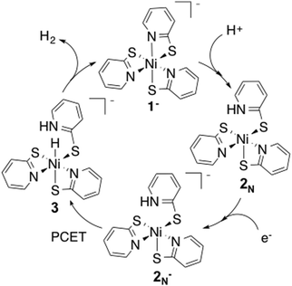
Finding an efficient way to generate clean, low-cost energy is fundamental for environmental preservation and the improvement of living conditions for people in developing nations.1,2 Converting water to H2 as a clean fuel source using precious-metal free water reduction catalysts is of great interest.3–5 Both Co and Ni catalysts have been shown to be effective for water reduction.6–17 Specifically, the Ni–pyridine 2-thiolate Ni(PyS)3− catalyst has shown high activity and stability in photochemical systems.6,11The reaction pathway for this catalyst has been proposed from experimental observations (Fig. 1).6 In the proposed reaction pathway, Ni(PyS)3− (1−) undergoes protonation at a pyridyl nitrogen to form 2N, followed by reduction (2N−), then proton coupled electron transfer (PCET) to make the hydride, 3, and finally release of H2. In this study we examine electronic and structural properties of the reaction intermediates using DFT calculations.
A recent review highlighted several advancements towards using computations in rational design of water-reduction catalysts.18 Computational methods have previously been used to enhance knowledge of hydrogen evolution catalytic cycles in a similar manner,12,15,19–25 including those of Co glyoxime26–28 and Ni P2N229–32 type catalysts. The objective of this paper is to use DFT methods to probe the intermediates in the proton reduction pathway of Ni(PyS)3−. DFT can provide information on reaction intermediates that are difficult to probe experimentally, e.g. spin state, localization of charges and structure. Also identification of high-energy intermediates could help target catalyst modification to increase catalytic turnover frequency.
To this end, we have determined the energies of key intermediates through frequency calculations, identified a potential transition state and generated spin density maps for intermediates in various spin states. Geometries were determined through optimization calculations performed on possible intermediates of the reaction pathway. Optimized structures allowed us to explore the possibility of solvent coordination at a vacant site on the nickel during the catalytic cycle.
Methods
DFT calculations were performed using the Gaussian 09 suite of programs.33 Previous reports use either B3P8634–36/6-31+G(d) or B3LYP35,37/6-31+G(d) for similar Ni based catalysts.21,24 The structure of the starting catalyst 1− was optimized using both levels of theory in the gas phase and using the CPCM38,39 solvation model for water. It has been reported that the catalyst is active in a solvent mixture containing water and ethanol, however since the dielectric constant of water is higher than ethanol we used a pure water solvation model. The Ni–heteroatom bond lengths from the optimized geometries were compared to the corresponding crystal structure (Table 1).40 Average deviation from crystal structure bond lengths obtained from B3LYP is 2.07% while the deviation obtained using B3P86 is only 0.42% (see ESI† for errors). Differences in bond lengths between the gas phase optimization and the optimized structure using a solvent model are negligible, however the total energy was lower using the solvent model. For these reasons, subsequent calculations were performed using B3P86/6-31+G(d) with the CPCM water solvation model.| Crystal structure | B3LYP | B3LYP | B3LYP | B3P86 | B3P86 | B3P86 | |
|---|---|---|---|---|---|---|---|
| Ethanol CPCM | Gas | Water CPCM | Ethanol CPCM | Gas | Water CPCM | ||
| Bond | Length | Length | Length | Length | Length | Length | Length |
| Ni–N1 | 2.034 Å | 2.069 Å | 2.064 Å | 2.090 Å | 2.063 Å | 2.071 Å | 2.062 Å |
| Ni–N2 | 2.041 Å | 2.102 Å | 2.101 Å | 2.065 Å | 2.041 Å | 2.044 Å | 2.044 Å |
| Ni–N3 | 2.081 Å | 2.063 Å | 2.071 Å | 2.070 Å | 2.044 Å | 2.038 Å | 2.041 Å |
| Ni–S1 | 2.541 Å | 2.565 Å | 2.609 Å | 2.603 Å | 2.549 Å | 2.554 Å | 2.549 Å |
| Ni–S2 | 2.526 Å | 2.608 Å | 2.604 Å | 2.596 Å | 2.560 Å | 2.548 Å | 2.563 Å |
| Ni–S3 | 2.518 Å | 2.607 Å | 2.564 Å | 2.613 Å | 2.545 Å | 2.514 Å | 2.545 Å |
We used the catalytic cycle laid out in the literature as a starting point for selecting intermediates of interest.6 Structures of other isomers, and alternative reaction paths were also considered. Structures of these intermediates were optimized with DFT to determine specific complex geometries, spin states, and total energies. Spin density maps of doublet, triplet and quartet states were generated using the cubegen utility in Gaussian 09.
The total energy of each intermediate was obtained from the total thermal and electronic energy from the frequency calculation (see ESI†). The ΔG° for each reaction at standard state was determined using eqn (1). Gproducts and Greactants is the sum of the total internal energy of the reaction components.
| ΔG°rxn = Gproducts − Greactants | (1) |
The reduction potentials were determined using isodesmic reactions with the reduction of 2N to 2N− as the reference reaction (E°ref = −1.18 V vs. SCE).6 Using the experimentally reported reduction of the catalyst results in the calculated reduction potential of 2N being accurate by design. This method avoids issues of experimental reduction potentials reported in various solvents. The use of isodesmic reactions and experimentally determined reduction potentials as references eliminates systematic computation errors and results in a reported accuracy of the method of ca. 0.1 V.21 Using the free energy change of the reaction below, the reduction potentials were determined.
| Ox + 2N− → Red + 2N | (2) |
Ox and Red are the oxidized and reduced intermediates of interest. The ΔG° for these isodesmic reactions was used to calculate E° of the desired reaction using the eqn (3) where F is Faraday's constant. All reduction potentials are reported vs. SCE to match experiment.
| E° = −ΔG°/F + E°ref | (3) |
Since protonation at the ligand involves breaking the Ni–S or Ni–N bond, using an isodesmic reaction as a reference for determining the reaction pKa becomes problematic. The reported error for pKa calculations with B3P86 level of theory is 2.6 units if no isodesmic reaction is used to correct for systematic errors.41 To determine pKa's for the possible protonation sites and to calculate G the value of −264 kcal mol−1 for water solvated H+ was used.21 The pKa was calculated using eqn (4), using ΔG for the corresponding reaction below where B is the intermediate being protonated (see ESI† for more details).
B + H+ → BH pKa = −ΔG/RT![[thin space (1/6-em)]](https://www.rsc.org/images/entities/char_2009.gif) ln ln![[thin space (1/6-em)]](https://www.rsc.org/images/entities/char_2009.gif) 10 10 | (4) |
Energy coordinate diagrams were generated from the free energy change of each step in the catalytic cycle with the reduction potentials referenced either to SCE or −1.3 V vs. SCE and a pH of 12 as indicated in the figure captions. These were chosen to indicate the reaction coordinates at experimental conditions. The reaction was optimal at pH 12 and −1.3 V is the reduction potential of reduced fluorescein dye. The ΔG° values reported in the text are standard state, and the values in the figures are referenced to these experimental values. Any interaction with the sacrificial electron donor triethylamine, or the decomposition products of triethylamine were not considered in this study.
The structure of the transition state was determined using the QST2 method with compound 3 and 1−/H2 as the input geometries. The frequency calculation for the transition state structure showed one negative frequency. The normal mode for the negative frequency was identified as corresponding to the H–H bond stretch, suggesting that it is the correct transition state for the formation of H2.
Results and discussion
Protonation
Experimental results indicate protonation occurs prior to reduction; a reduction wave is only observed after addition of acid to the catalyst.11 We calculated the reduction potential of 1− to be −1.9 V. This potential is too negative to be reduced under experimental conditions, corroborating that protonation must occur first.Protonation can occur at either the sulphur or pyridyl nitrogen; resulting in dechelation of the ligand. Protonation of the pyridyl nitrogen is proposed by Eisenberg et al. A crystal structure of a similar compound, Ni(H-PyS)4,6 shows protonation of the pyridyl nitrogen in a square planar compound with only remaining sulphur coordination. However, for a similar complex with a tris-phosphine chelating ligand and a PyS ligand, it has been suggested that protonation occurs at the sulphur without detachment from the Ni, followed by proton migration to the detached pyridyl nitrogen.42 To probe the preferred protonation site we optimized structures with one protonated sulphur, both attached (ring closed) 2Sc and detached (ring open) 2So from the Ni, and the protonated pyridyl N (ring open), 2N. The open and closed structures of the protonated sulphur optimize to the same open structure, 2s (Fig. 2). Dechelation of the protonated ligand results in a square pyramidal structure. The meridinal geometry of 1− results in two distinct pyridyl nitrogen sites. Protonation to form the cis isomer is statistically more likely, and slightly lower in energy; as such we only consider the cis geometry.
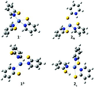 | ||
| Fig. 2 Optimized structures of 1−, 2N, 2S and 12−. Grey, carbon; blue, nitrogen; yellow, sulphur; white, hydrogen; light blue, nickel. | ||
Using the energy of a solvated proton, the pKa for the species protonated at the sulphur and nitrogen were calculated to be 3.2 and 9.9 respectively (eqn (5) and (6) in standard state). The experimentally determined pKa of the catalyst is 12.1.11 The calculated pKa of 9.9 for the species protonated at the pyridyl nitrogen is within the 2.6 unit error typical for this method.21 The photocatalytic experimental reaction conditions report an optimal pH of 12. Protonation at the sulphur under these conditions is less favoured than protonation at the nitrogen and unlikely to occur (Fig. 3).
| 1− + H+ → 2S ΔG° = −4.31 kcal mol−1, pKa 3.2 | (5) |
| 1− + H+ → 2N ΔG° = −13.5 kcal mol−1, pKa 9.9 | (6) |
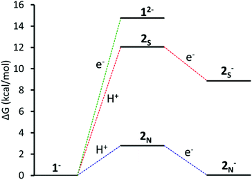 | ||
| Fig. 3 Energy coordinate diagram vs. SCE at pH 12 of: Green: reduction of 1−; red: protonation at S followed by reduction; blue: protonation at pyridyl N followed by reduction. | ||
The calculated pKa for the species protonated at the pyridyl nitrogen supports that the catalytic cycle starts with protonation and subsequent reduction to form complex 2N−.
Geometry and water coordination
The catalyst, 1− is in an octahedral configuration. Initial protonation at a pyridyl nitrogen detaches the nitrogen at which point the complex is five-coordinate square-pyramidal leaving a vacant coordination site that could be occupied by solvent. The reaction solvent is a mixture of water and ethanol. Due to electrostatic potential and size of water we considered water coordination. To explore water coordination, we optimized the geometry and performed frequency calculations on the intermediates both with (4) and without (2N) a coordinated explicit water molecule (see ESI† for structure). 4 has a similar geometry as 2N, but with a water molecule occupying the vacant coordination site. Coordination of water to the vacant site is not energetically favourable for the protonated compound 2N by 6.42 kcal mol−1 (eqn (7)). The standard state is calculated with 1 M H2O; considering water as a solvent (55 M) this reaction is also not spontaneous. Furthermore, the reduction potential of 4 is −2.4 V, far from the experimentally observed value of −1.18 V.| 2N + H2O → 4 ΔG° = +6.42 kcal mol−1 | (7) |
| 2N− + H2O → 4− ΔG° = +34.96 kcal mol−1 | (8) |
After reduction the catalyst is still five coordinate. Likewise, water coordination after reduction is thermodynamically unfavourable with ΔG = +34.96 kcal mol−1 (eqn (8)). Calculations indicate that although there is a vacant coordination site on complex 2N and 2N−, water coordination to make 4 and 4− is not energetically favourable and is unlikely to occur.
However, coordination of a hydroxide to 2N to get 5 ion is exothermic, ΔG° = −11.38 kcal mol−1. The reduction potential of 5 is −1.7 V, outside the potential available under experimental conditions indicating that either reduction of 2N is kinetically favoured over hydroxide coordination or hydroxide coordination is reversible. This intermediate is unlikely to contribute to the catalytic cycle and is not considered further.
Spin state
The spin state of the complex is set by the user in the calculation setup, allowing both investigation into various spin states and room for error in choosing the incorrect spin state. For most organic molecules all electrons are paired and a singlet spin state can be assumed, however transition metal complexes are more complicated.43,44 Six coordinate Ni(II) is octahedral d8 so 1− and 2N have a triplet ground state with two unpaired electrons. When 2N was optimized as a singlet, the geometry changed to square planar with dechelation of two ligands and the complex was 7.0 kcal mol−1 higher energy than the triplet.Intermediate 2N− could be either a doublet with an unpaired electron on the metal, or a quartet with one unpaired electron on a ligand and two on the metal. The geometry was optimized for the complex in both spin states. Many redox catalysts operate through redox active (non-innocent) ligands.45,46 Spin localization can be difficult to determine experimentally for intermediates not long-lived enough for electron paramagnetic resonance (EPR) experiments, however localization of spin density can be determined through computationally generated spin density maps.
Spin density maps were generated to localize the electron density of the unpaired electrons (Fig. 4). The geometry optimizations of 2N− as a doublet and quartet show minimal change in structure. However, from the spin density maps it is evident that the electron density of the doublet of complex 2N− is heavily localized on the central nickel atom. The quartet spin has electron density more delocalized across the ligands, predominantly on the protonated pyridyl ligand. The doublet zero-point energy is lower by 87.2 kcal mol−1 than the quartet. The lower energy of the doublet state indicates that reduction of 2N results in a doublet state with electron density on the Ni centre, not the ligand.
Hydride formation
The final intermediate in the proposed reaction pathway is a nickel hydride (3) formed through a second reduction and protonation. Experimentally the hydride has not been isolated but is thought to form through a concerted proton coupled electron transfer (PCET) step.6 The hydride could be formed in one PCET step, or in two sequential steps, protonation and reduction.47,48 Optimized geometries for the reduced compound, 6, and the protonated compound, 7, were found to give stable structures suggesting a possible sequential reaction pathway (Fig. 5). Considering these intermediates the following options were considered: (A) reduction of 2N− to yield complex 6, then addition of a proton at the nickel centre to yield complex 3, (B) reduction of 2N− with concerted migration of the proton to the Ni, to yield complex 8 and subsequent protonation to yield complex 3 (C) protonation of the nickel centre of 2N− to yield complex 7, then reduction of the complex to again form 3, and (D) concerted PCET, which was modelled by addition of a proton at the nickel centre and simultaneous addition of an electron. Note the final intermediate, 3, is the same in all four options. | ||
| Fig. 5 PCET alternative intermediates, reduction, 6; protonation, 7; and reduction with concerted proton migration, 8. | ||
To begin, we consider reduction of 2N− to yield 6. The calculated reduction potentials for 2N− is −2.1 V. Under experimental photocatalytic conditions, electron transfer is thought to occur through a reductive quenching mechanism such that the electrons would come from reduced dye, fluorescein, at a potential of −1.3 V.11 This would not have enough potential to reduce 2N−. Due to the high reduction potential for 2N−, we no longer consider option A.
Option B, proton transfer from the pyridyl nitrogen to the metal centre with 2N− reduction, results in a hydride intermediate, 8 that is −42.14 kcal mol−1 more stable than complex 6. Concerted proton transfer to the Ni and reduction has a calculated potential of −1.8 V. Protonation of this complex is unfavourable by 30.49 kcal mol−1. Attempts to model an intermolecular PCET reaction with an explicit water molecule did not optimize to a protonated structure.
Option C, formation of 7, is exergonic by 11.96 kcal mol−1, this corresponds to a pKa of 8.8 for the Ni–H on compound 7.
| 2N− + H+ → 7 ΔG° = −11.96 kcal mol−1, pKa 8.8 | (9) |
Experimentally, the reaction occurs at a pH of 12.11 Even considering a 2.6 pKa unit margin of error, equilibrium likely lies towards having higher concentrations of 2N−, rather than protonated compound 7. Interestingly Eisenberg et al. noted a small reduction wave in the CV around −1.0 V that did not show any catalytic behaviour and that disappeared upon neutralization.6 Our results indicate this peak may correspond to reduction of 7 that has a calculated reduction potential of −1.0 V. At pH 12 protonation of 2N− is only exothermic by 4.41 kcal mol−1. Although only small amounts of 7 may be formed it would be easily reduced, driving this reaction.
Finally, eqn (10), concerted protonation and reduction was calculated to require 2.3 kcal mol−1. In the absence of kinetic data, we hypothesize that the transition from 2N− to 3 will have a lower barrier of activation than the transition from 7 to 3 (Fig. 6).
| 2N− + e− + H+ → 3 ΔG° = 2.35 kcal mol−1 | (10) |
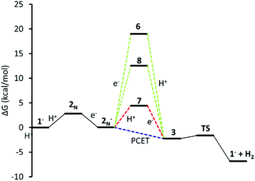 | ||
| Fig. 6 Energy coordinate diagram for alternative paths to PCET. Red: 2N− is first protonated (7), then reduced at the Ni centre; green reduced to 6, and proton migration, 8; blue: concerted PCET. | ||
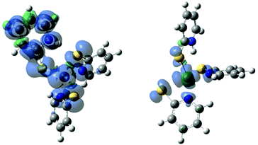
The ground state of the hydride, 3, and the doubly reduced compound, 6, could be either a singlet state or a triplet state. Knowing where electron density is localized is important for ligand design. The energy of the triplet state for 3 is 61.7 kcal mol−1 lower in energy than the singlet state. The spin density map of 3 in a triplet state shows electron density on both the metal and the hydride, supporting the hydride designation of this complex (Fig. 7). Likewise, the triplet state of 6 is 35.6 kcal mol−1 lower in energy than the singlet. The electron density is located primarily on the protonated ligand (Fig. 7). These electron density maps suggest that unlike the first reduction, which was centred on the nickel, the second reduction is ligand based.
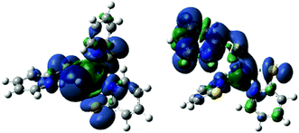 | ||
| Fig. 7 Spin density map for 3, triplet, left, and 6, triplet, right, showing spin density located heavily on the hydride and protonated PyS ligands respectively. | ||
Hydrogen release
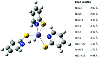
After formation of the Ni hydride, 3, the catalyst has the two electrons and two protons required to produce H2. In the octahedral complex 3 the proton on the pyridyl nitrogen and Ni are close together (1.44 Å). In the optimized structure of the transition state the H–H bond length is 0.98 Å. The Ni–H bond length has extended to 1.72 Å, and the N–H bond length is 1.33 Å (Fig. 8). The transition state, TS, is only 0.64 kcal mol−1 higher in energy than 3. The release of H2 from the transition state is exergonic by 5.2 kcal mol−1, suggesting that H2 elimination has a low barrier of activation.Complete catalytic cycle
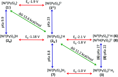
Thermodynamic cycles were used to determine the most catalytically favoured pathway. The reduction potentials and pKa's connecting each intermediate are shown in Fig. 9.49,50 We calculated that reduction of 1− prior to protonation would require a potential of −1.9 V. Thus, it is evident that initial protonation is more favourable than initial reduction of 1−. This is in agreement with electrochemical experimental data indicating that without acid present in solution, no cyclic voltammetry wave is observed at potentials less negative than −2.0 V.11 The calculated pKa of 2N is 9.9, which is in relatively good agreement with the experimentally measured pKa of 12. Given the 2.6 unit margin of error, protonation of compound 1− is likely at pH 12, which was used in the photocatalytic experiment.From experiment it is still unclear if the formation of the hydride, 3, occurs through sequential or concurrent protonation and reduction. Structures of protonated intermediate 7 and reduced intermediates 6 and 8 were optimized suggesting these may be stable intermediates and sequential PCET may occur. However, the reduction potential of 2N− to make 6 and 8 are −2.1 V and −1.8 V respectively, making formation of these intermediates unlikely (Fig. 9). The protonated compound 7, if present in solution, is likely found in low concentrations, however the low reduction potential would drive this reaction toward the hydride 3. Additionally, electrochemical data indicates the presence of a second reduction at −1.0 V. Our calculated reduction potential of −1.0 V for 7 indicates correct identification of this reduction wave. Taking into consideration the pKa's and reduction potentials a sequential PCET where protonation occurs before reduction is most consistent with experimental results. However, the overall ΔG of 2.35 kcal mol−1 for PCET, where 2N− becomes 3, suggests a low barrier to a concerted mechanism. The structure of the hydride 3 shows the protons in close proximity, requiring very little energy to generate the transition state for H2 elimination to regenerate the initial catalyst 1−.
These calculations suggest two main routes to improve catalyst design, first sterically hindering the space around the nickel could prevent coordination of a hydroxide that forms a complex that cannot continue through the catalytic cycle. Secondly, the high energy steps are protonations, thus increasing the basicity of the ligand may result in a more active catalyst. Also the reduction potentials determined suggest that a less reducing photosensitizer would still provide the potential needed to drive this reaction and could allow for ideal matching of photosensitizer and catalysts. Further studies into this hypothesis are underway.
Conclusions
This study explored the Ni(PyS)3− (1−) intermediates throughout the catalytic cycle of proton reduction. Specifically, DFT calculations support the experimentally proposed catalytic cycle while providing insight into intermediate complex geometries and electron localization of the reduced intermediates. Catalyst protonation at the pyridyl nitrogen is required to lower the reduction potential of the catalyst so that it can be reduced by the photosensitizer. This protonation leads to ligand dechelation, leaving a vacant coordination site. Water coordination following initial protonation is thermodynamically unfavourable, however hydroxide coordination is exothermic and could lead to an intermediate that would not continue through the catalytic cycle. The spin density map of the reduced catalyst (2N−) reveals electron density is localized at the metal centre. The formation of the nickel-hydride intermediate 3 occurs through sequential proton-electron transfer, and the hydride nature was confirmed through a spin density map. H2 elimination from this species is not energetically demanding, as demonstrated through determination of the transition state energy. Through the use of DFT calculations, we elucidated features of intermediates along the catalytic cycle of Ni(PyS)3− which were experimentally unexplored.Acknowledgements
The authors would like to thank Portland State University for funding.References
- N. S. Lewis, MRS Bull., 2007, 32(10), 808–820 CrossRef.
- E. Martinot, A. Chaurey, D. Lew, J. R. Moreira and N. Wamukonya, Annu. Rev. Energy Environ., 2002, 27(1), 309–348 CrossRef.
- Z. Han and R. Eisenberg, Acc. Chem. Res., 2014, 47(8), 2537–2544 CrossRef CAS PubMed.
- P. Du and R. Eisenberg, Energy Environ. Sci., 2012, 5(3), 6012 CAS.
- A. Das, Z. Han, W. W. Brennessel, P. L. Holland and R. Eisenberg, ACS Catal., 2015, 5(3), 1397–1406 CrossRef CAS.
- Z. Han, L. Shen, W. W. Brennessel, P. L. Holland and R. Eisenberg, J. Am. Chem. Soc., 2013, 135(39), 14659–14669 CrossRef CAS PubMed.
- T. L. James, L. Cai, M. C. Muetterties and R. H. Holm, Inorg. Chem., 1996, 35(14), 4148–4161 CrossRef CAS PubMed.
- Z. Han, F. Qiu, R. Eisenberg, P. L. Holland and T. D. Krauss, Science, 2012, 338(6112), 1321–1324 CrossRef CAS PubMed.
- M. P. McLaughlin, T. M. McCormick, R. Eisenberg and P. L. Holland, Chem. Commun., 2011, 47(28), 7989–7991 RSC.
- P. A. Jacques, V. Artero, J. Pécaut and M. Fontecave, Proc. Natl. Acad. Sci. U. S. A., 2009, 106(49), 20627–20632 CrossRef CAS PubMed.
- Z. Han, W. R. McNamara, M.-S. Eum, P. L. Holland and R. Eisenberg, Angew. Chem., Int. Ed., 2012, 51(7), 1667–1670 CrossRef CAS PubMed.
- S. Cherdo, S. El Ghachtouli, M. Sircoglou, F. Brisset, M. Orio and A. Aukauloo, Chem. Commun., 2014, 50(88), 13514–13516 RSC.
- S. Varma, C. E. Castillo, T. Stoll, J. Fortage, A. G. Blackman, F. Molton, A. Deronzier and M.-N. Collomb, Phys. Chem. Chem. Phys., 2013, 15(40), 17544–17552 RSC.
- B. D. Stubbert, J. C. Peters and H. B. Gray, J. Am. Chem. Soc., 2011, 133(45), 18070–18073 CrossRef CAS PubMed.
- B. Mondal, K. Sengupta, A. Rana, A. Mahammed, M. Botoshansky, S. G. Dey, Z. Gross and A. Dey, Inorg. Chem., 2013, 52(6), 3381–3387 CrossRef CAS PubMed.
- T. M. McCormick, B. D. Calitree, A. Orchard, N. D. Kraut, F. V. Bright, M. R. Detty and R. Eisenberg, J. Am. Chem. Soc., 2010, 132(44), 15480–15483 CrossRef CAS PubMed.
- L. Gan, T. L. Groy, P. Tarakeshwar, S. K. S. Mazinani, J. Shearer, V. Mujica and A. K. Jones, J. Am. Chem. Soc., 2015, 137(3), 1109–1115 CrossRef CAS PubMed.
- S. Raugei, D. L. DuBois, R. Rousseau, S. Chen, M.-H. Ho, R. M. Bullock and M. Dupuis, Acc. Chem. Res., 2015, 48(2), 248–255 CrossRef CAS PubMed.
- A. Bhattacharjee, E. S. Andreiadis, M. Chavarot-Kerlidou, M. Fontecave, M. J. Field and V. Artero, Chemistry, 2013, 19(45), 15166–15174 CrossRef CAS PubMed.
- B. H. Solis and S. Hammes-Schiffer, J. Am. Chem. Soc., 2012, 134(37), 15253–15256 CrossRef CAS PubMed.
- B. H. Solis and S. Hammes-Schiffer, Inorg. Chem., 2014, 53(13), 6427–6443 CrossRef CAS PubMed.
- S. Hammes-Schiffer, Acc. Chem. Res., 2009, 42(12), 1881–1889 CrossRef CAS PubMed.
- E. S. Wiedner, A. M. Appel, D. L. Dubois and R. M. Bullock, Inorg. Chem., 2013, 52(24), 14391–14403 CrossRef CAS PubMed.
- S. Chen, S. Raugei, R. Rousseau, M. Dupuis and R. M. Bullock, J. Phys. Chem. A, 2010, 114(48), 12716–12724 CrossRef CAS PubMed.
- R. Z. Liao, M. Wang, L. Sun and P. E. M. Siegbahn, Dalton Trans., 2015, 44, 9736–9739 RSC.
- J. T. Muckerman and E. Fujita, Chem. Commun., 2011, 47(46), 12456–12458 RSC.
- B. H. Solis and S. Hammes-Schiffer, Inorg. Chem., 2011, 50(21), 11252–11262 CrossRef CAS PubMed.
- B. H. Solis, Y. Yu and S. Hammes-Schiffer, Inorg. Chem., 2013, 52(12), 6994–6999 CrossRef CAS PubMed.
- U. J. Kilgore, J. A. S. Roberts, D. H. Pool, A. M. Appel, M. P. Stewart, M. R. Dubois, W. G. Dougherty, W. S. Kassel, R. M. Bullock and D. L. Dubois, J. Am. Chem. Soc., 2011, 133(15), 5861–5872 CrossRef CAS PubMed.
- M. O. Hagan, M. Ho, J. Y. Yang, A. M. Appel, M. R. Dubois, S. Raugei, W. J. Shaw, D. L. Dubois and R. M. Bullock, J. Am. Chem. Soc., 2012, 134(47), 19409–19424 CrossRef PubMed.
- L. E. Fernandez, S. Horvath and S. Hammes-Schiffer, J. Phys. Chem. C, 2012, 116(4), 3171–3180 CAS.
- S. Chen, M. H. Ho, R. M. Bullock, D. L. Dubois, M. Dupuis, R. Rousseau and S. Raugei, ACS Catal., 2014, 4(1), 229–242 CrossRef CAS.
- M. J. Frisch, G. W. Trucks, H. B. Schlegel, G. E. Scuseria, M. A. Robb, J. R. Cheeseman, G. Scalmani, V. Barone, B. Mennucci, G. A. Petersson, H. Nakatsuji, M. Caricato, X. Li, H. P. Hratchian, A. F. Izmaylov, J. Bloino, G. Zheng, J. L. Sonnenberg, M. Hada, M. Ehara, K. Toyota, R. Fukuda, J. Hasegawa, M. Ishida, T. Nakajima, Y. Honda, O. Kitao, H. Nakai, T. Vreven, J. A. Montgomery Jr., J. E. Peralta, F. Ogliaro, M. Bearpark, J. J. Heyd, E. Brothers, K. N. Kudin, V. N. Staroverov, R. Kobayashi, J. Normand, K. Raghavachari, A. Rendell, J. C. Burant, S. S. Iyengar, J. Tomasi, M. Cossi, N. Rega, J. M. Millam, M. Klene, J. E. Knox, J. B. Cross, V. Bakken, C. Adamo, J. Jaramillo, R. Gomperts, R. E. Stratmann, O. Yazyev, A. J. Austin, R. Cammi, C. Pomelli, J. W. Ochterski, R. L. Martin, K. Morokuma, V. G. Zakrzewski, G. A. Voth, P. Salvador, J. J. Dannenberg, S. Dapprich, A. D. Daniels, Ö. Farkas, J. B. Foresman, J. V. Ortiz, J. Cioslowski and D. J. Fox, Gaussian 09, Revision D.01, Gaussian, Inc., Wallingford CT, 2009 Search PubMed.
- A. D. Becke, Phys. Rev. A, 1988, 38(6), 3098–3100 CrossRef CAS.
- B. Miehlich, A. Savin, H. Stoll and H. Preuss, Chem. Phys. Lett., 1989, 157(3), 200–206 CrossRef CAS.
- J. P. Perdew, Phys. Rev. B: Condens. Matter, 1986, 33(12), 8822–8824 CrossRef.
- C. Lee, W. Yang and R. G. Parr, Phys. Rev. B: Condens. Matter, 1988, 37(2), 785–789 CrossRef CAS.
- V. Barone and M. Cossi, J. Phys. Chem. A, 1998, 102(11), 1995–2001 CrossRef CAS.
- M. Cossi, N. Rega, G. Scalmani and V. Barone, J. Comput. Chem., 2003, 24, 669–681 CrossRef CAS PubMed.
- P. E. N. Schn, P. N. Schn, S. G. Rosenfield, H. P. Berends, L. Gelmini, D. W. Stephan and P. K. Mascharak, Inorg. Chem., 1987, 26(17), 2792–2797 CrossRef.
- X. Qi, L. Liu, Y. Fu and Q. Guo, Organometallics, 2006, 25(25), 5879–5886 CrossRef CAS.
- A. L. Petrou, A. D. Koutselos, H. S. Wahab, W. Clegg, R. W. Harrington and R. Henderson, Inorg. Chem., 2011, 50(3), 847–857 CrossRef CAS PubMed.
- C. J. Cramer and D. G. Truhlar, Phys. Chem. Chem. Phys., 2009, 11(46), 10757–10816 RSC.
- J. Cano, E. Ruiz, S. Alvarez and M. Verdaguer, Comments Inorg. Chem., 1998, 20(1), 27–56 CrossRef CAS PubMed.
- O. R. Luca, J. D. Blakemore, S. J. Konezny, J. M. Praetorius, T. J. Schmeier, G. B. Hunsinger, V. S. Batista, G. W. Brudvig, N. Hazari and R. H. Crabtree, Inorg. Chem., 2012, 51(16), 8704–8709 CrossRef CAS PubMed.
- V. Lyaskovskyy and B. De Bruin, ACS Catal., 2012, 2(2), 270–279 CrossRef CAS.
- R. Ciancanelli, B. C. Noll, D. L. DuBois and M. Rakowski DuBois, J. Am. Chem. Soc., 2002, 124(12), 2984–2992 CrossRef CAS PubMed.
- S. Hammes-Schiffer and A. V. Soudackov, J. Phys. Chem. B, 2008, 112(45), 14108–14123 CrossRef CAS PubMed.
- D. D. M. Wayner and V. D. Parker, Acc. Chem. Res., 1993, 26(6), 287–294 CrossRef CAS.
- S. Chen, R. Rousseau, S. Raugei, M. Dupuis, D. L. DuBois and R. M. Bullock, Organometallics, 2011, 30(22), 6108–6118 CrossRef CAS.
Footnote |
| † Electronic supplementary information (ESI) available: Bond length errors, total energies and coordinates for all reported compounds. See DOI: 10.1039/c5dt02044a |
| This journal is © The Royal Society of Chemistry 2015 |

