Controlled fabrication of porous metals from the nanometer to the macroscopic scale
Niklaus
Kränzlin
and
Markus
Niederberger
*
Laboratory for Multifunctional Materials, Department of Materials, ETH Zürich, Vladimir-Prelog-Weg 5, 8093 Zürich, Switzerland. E-mail: markus.niederberger@mat.ethz.ch
First published on 6th March 2015
Abstract
Porous metals such as foams and sponges are produced by a wide variety of industrially applied techniques mainly for load bearing and structural applications. Their functional properties are much less explored, mainly due to the difficulty to simultaneously control the relative density, the pore structure and the macroscopic shape during their fabrication, which however would be required to control the functionality. Accordingly, to take full advantage of the mechanical and functional properties of porous metals, new synthesis methodologies have to be developed that address all structural features from the nanoscopic to the macroscopic scale. Thus, in this review we provide an overview of the different techniques to prepare porous metals with the focus on evaluating them with respect to their flexibility and ability to control and tailor the architecture over several length scales. We discuss the advantages and limitations of the different methods, correlate them with the properties of the resulting porous metals and present potential applications. In the last part of the review, we outline a wet-chemical deposition route to metallic copper, which can be applied to a wide variety of flat and spherical substrates, giving access to both copper sponges with defined porosity and relative density as well as complex macroscopic shapes and to copper line patterns on flexible substrates.
1. Introduction
Cellular metals, metal foams, metal sponges, metal aerogels, (nano-)porous/(ultra-)low density metal structures – all these expressions, and many others, are commonly used to describe the geometrical (i.e., the macroscopic shape of the body) and structural (i.e., the inner architecture) configuration of a metal–gas-composite, usually with relative mass-densities ranging from 0.8 (ref. 1) down to 0.001.2There are many ways to classify such materials, typically referring to the structural connectivity of the cell walls and cell edges enclosing the air bubbles and to the corresponding feature size of either of them. A simple discrimination can be made between structures, where the pores are interconnected and percolating, referred to as sponges, and structures, where the pores are isolated from each other, referred to as foams.3–6Fig. 1 points out the difference between a closed-cell polyurethane foam and an open-cell polyurethane sponge revealing the specific nomenclature of the corresponding structural elements as it is also used for porous metals. Such a classification of the numerous different porous metal structures proved to be useful during the last century.1,3–5,7–14 Although closed cells typically still contain a few holes due to missing cell walls or faces, like those displayed in Fig. 1a, it is still useful to distinguish them from the open-cell sponges with their extensive porosity (cf.Fig. 1b).
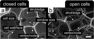 | ||
| Fig. 1 Nomenclature of the structural elements building up cellular porous materials. (a) Closed-cell polyurethane foam. (b) Open-cell polyurethane sponge. Reproduced with permission from ref. 15, Copyright 2005, Elsevier Inc. | ||
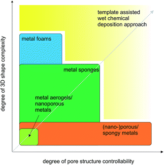
For most applications it is important to have the possibility to simultaneously engineer the pore structure and the macroscopic appearance of the porous metals, which means that the fabrication process has to provide control over nano- and microscale features as well as over macroscopic dimensions up to several centimeters.16–31 Bridging so many length scales is hardly possible by one process. Often a sequence of processing steps has to be applied, whose number is dependent on the structural complexity of the final porous material. Taking these multiscale aspects into account, we decided to structure our review not just based on open or closed-cells, but rather on the degree of the complexity of the macroscopic shape. Fig. 2 summarizes this concept. On the top level, Fig. 2 gives an overview of the classification of porous metals as it is used throughout the manuscript. Additionally, the most common preparation strategies for metal foams, metal sponges and nanoporous metals are listed. Independent of the connectivity of the pores, metal foams and sponges can exhibit simple or complex macroscopic shapes, which define the processing route required for their production. In the most cases, however, a method suitable for a specific shape might not be the best option for controlling the microscopic features. Therefore, the production strategy greatly affects the efficiency and performance of the porous metal structure in its final application. Some applications rely on more complex geometries and pore structures than others, which is indicated on the bottom part of Fig. 2.
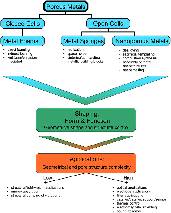 | ||
| Fig. 2 The open and closed porous metal structures grouped depending on the complexity of their macroscopic geometry together with their functional/structural properties. | ||
In general the field of applications for a porous metal structure is strongly dictated by three parameters: (i) the composition, (ii) the macroscopic shape, and (iii) the pore structure. The composition determines the intrinsic properties and thus decides on whether or not a specific metal or alloy fulfills the targeted physical (density, electrical/thermal conductivity, strength, elasticity, ductility, machinability) or chemical (oxidation behavior, corrosion stability) requirements. The macroscopic shape is critical for the integration into pre-designed devices or for their combination with other materials. Finally, the pore structure (relative density, surface area density, mechanical stability, pore size, pore size distribution, connectivity of pores) defines the efficiency of the material during operation. Only when all these three characteristics are carefully engineered, the material can be considered as possible candidate for a given application. But even nowadays with state-of-the-art fabrication routes, these three parameters can hardly be optimized simultaneously, so that porous metals find applications mostly in niche markets.4,5 Accordingly, novel, simple and inexpensive preparation techniques have to be developed, not only taking advantage of the gained knowledge during the last nearly 90 years4 of research and development in the field of porous metals, but also learning from other fields such as colloid chemistry or nanoparticle research.
2. Overview of general fabrication routes to porous metals and of selected commercial products
In this section we provide a brief introduction to the various techniques to fabricate metal foam structures and metal sponges. Several industrially applied methods are summarized and the corresponding commercially available products are presented. The connectivity of the pores represents a major factor in determining the application and therefore this aspect is elaborated later in this section. The advantages and limitations of all these techniques in relation to pore structure control will be discussed again in much more details later in the review. For a more in-depth discussion on the history of light-metal foams, we also recommend the review article by John Banhart.4Some of the first metal foams were prepared by using blowing agents such as TiH2 or ZrH2 mixed into aluminium and aluminium alloy melts.1,3–5,7,11,13 At a given temperature the blowing agent particles decompose under the release of hydrogen bubbles. For the stabilization of the bubbles in the melt and for further evolution of the foam structure ceramic additives are used,1,8,11 although their actual function is still a matter of intense discussion. In addition to the interpretation that they mainly help to increase the viscosity, modify the surface energy and thus minimize the drainage of the melt inside the bubble walls/struts, other stabilization mechanisms were proposed, too. Heim et al.32 observed that Mg-containing aluminium alloys show higher affinity towards the formation of an oxide layer at the liquid gas interface, which leads to a long-term stabilization of the foam. Moreover, the presence of SiC and TiB2 particles can lead to a stabilizing effect due to the formation of physical barriers, hindering the loss of liquid by drainage. Another mechanism suggests that the oxide, which forms on the raw aluminium powder, breaks up during melting into residues that aggregate into an oxide network, and upon bubble nucleation this network fragments into clusters that act as physical barriers against cell wall thinning.33,34
The development of specific blowing agents4 together with the technology to stabilize the blown melts1,4 provided increasing control over the evolving pore structure and also over the macroscopic geometry of the body. Generally, two different methods for the introduction of the gas phase into the metal are available: direct (Fig. 3a–c) and indirect foaming techniques (Fig. 3d and e).
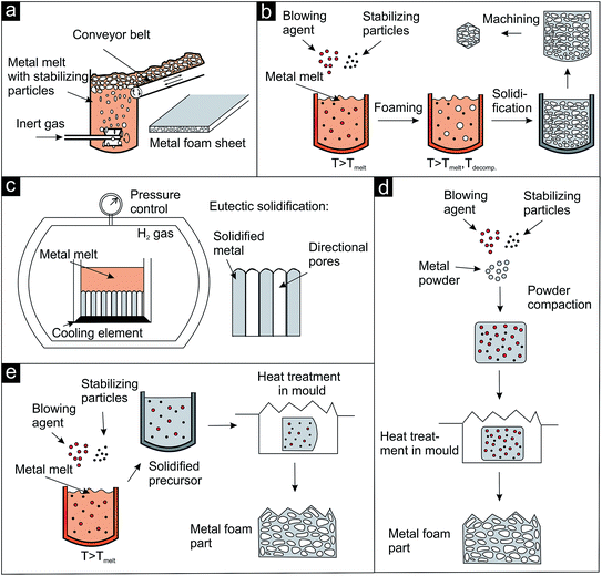 | ||
| Fig. 3 Schematic representation of direct and indirect foaming techniques applied for the preparation of metal foams (after ref. 1). (a–c) Direct foaming approaches, (d and e) indirect or precursor foaming techniques. Details see text. | ||
One-step approaches, where the gas source (external, blowing agent, dissolved gas in melts) is activated in or added to the molten metal are referred to as direct foaming techniques. An impeller can be used as external gas source as shown in Fig. 3a. The bubbles are formed at the bottom of the metal melt containing stabilizing particles (e.g., SiC) and move towards the surface. The blown melt is then skimmed off onto a conveyor belt and solidified.1 A commercially available product produced by this approach by Alusion is shown in Fig. 4a (available in panel dimensions up to 1219 mm × 2438 mm). If blowing agents are admixed to the metal melt, they are first decomposed and then the foam is solidified and, if desired, machined (Fig. 3b). Another direct foaming process makes use of the temperature and pressure dependent gas solubility in metals. In this case, the metal melt is charged with a gas (e.g., H2) to produce an eutectic metal gas mixture. Under controlled cooling and pressure conditions the melt undergoes a gas-eutectic solidification. The gas precipitates, leading to the formation of the pores in the final structure (Fig. 3c).1,4,35 The resulting foams usually exhibit elongated, directional and closed pores as shown in Fig. 4b.35
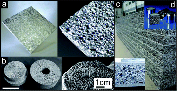 | ||
| Fig. 4 Representative examples of metallic foams prepared either by direct (a and b) or by indirect (c and d) foaming techniques. (a) Blown aluminium metal sheets prepared by introducing gas through an external source into the metal melt (Copyright 2003, Alusion™). (b) Magnesium (left) and copper (right) metal foam produced by gas-eutectic solidification process, white scale bar: 10 cm (reproduced with permission from ref. 35, Copyright 2004, Wiley-VCH Verlag GmbH & Co.). (c) Aluminium foam sandwich sheets (AFS sheets, Copyright 2014, pohltec metalfoam GmbH) and (d) foam filled pistons (FOAMINAL®, Copyright 2014, Fraunhofer IFAM) produced by precursor based foaming methods. | ||
In addition to direct methods, there are also precursor or indirect foaming techniques (Fig. 3d and e), where the solid material contains the gas source or the gas and has to be heated to induce the foaming process.4 The solid precursor can either be produced by simply homogenizing and compacting a mixture of metal powder, stabilizing and blowing agent (Fig. 3d) or by quickly mixing the stabilizing and blowing agent into the metal melt followed by cooling of the precursor body (Fig. 3e). The solid precursor is then transferred into a mold and heated to induce the foaming process. Aluminium foam sandwich metal sheets36 (panels available in dimensions up to 2500 mm × 1100 mm × 80 mm) and foam filled pistons as illustrative examples are pictured in Fig. 4c and d, respectively.
The lightweight bodies prepared by direct or indirect foaming techniques are large in scale and can be machined, joined and integrated into pre-fabricated structures. They are preferably found in structural load bearing,13,37,38 energy dissipation3,39 and biomedical applications.3,40 Examples include car frames,3,37 various kinds of housings, artificial bone materials or dental implants.3
A major focus of the development of new foaming methods addresses the production of smaller cells with uniform sizes. Pre-alloyed AlMg50 powder can be used as intrinsic gas source replacing TiH2, resulting in Al- and Zn-based foams with a large number of uniformly distributed small cells.41,42 The key to success of the approach lies in the spatially separated, homogeneous distribution of the gas source. Babcsan et al.43 report even better control over the cell size in aluminium foams by injecting bubbles with adjustable sizes through special nozzles. The foams can be cast into complex forms and even be re-melted without loss of foam integrity. Another recent report exemplifies that blowing agents or the injection of gases are not necessarily needed to e.g. foam aluminium or aluminium alloys.44 The method makes use of the hydrogen solubility of aluminium melts in ambient atmosphere. Applying a vacuum to molten aluminium induces precipitation and expansion of the dissolved hydrogen, enabling the preparation of pure aluminium and aluminium alloy foams without particles. Due to the inherent rough surface of foams, their combination with other materials is not trivial. Localized peak stresses at contact points could dramatically reduce the foams' performance under working conditions.45–49 It is possible to address this problem already during foam fabrication. Integral foam molding represents an industrially highly important approach, developed to produce metal foam parts with a dense metal skin and gradual transition to a foamed core in one step.50 The molten metal, typically aluminium or magnesium alloys, is injected into a steel mold together with the blowing agent. The cold mold wall induces the formation of a dense outer skin while in the core of the casting the foam is produced.50 In addition to the well-established and recently emerged technologies involving the direct or indirect foaming of liquid/powder metals,1,4,8 novel procedures have been developed, too. One such approach makes use of metallic particles as stabilizing agents of wet foams or emulsions, which are subsequently dried.51 The gas bubbles or oil droplets act as template and are reproduced in the final foam configuration after sintering of the dried green bodies.
The processes discussed up to here lead to metal foam architectures with closed-cell porosity. However, to further increase the functionality (Fig. 5), metals with open-cell porosity have to be produced. Fig. 5 exemplifies, whether the application field of a porous metal is more structural or functional depending on the degree of openness of the porosity. Structural applications include e.g. the damping of vibrations as they occur during operation of machines or inside running cars by filling hollow components with metal foams. By adjusting the pore structure and thus the relative density and modulus of elasticity, the resonant frequencies causing the parasitic sound waves can be up-shifted into frequency regions that will not be excited during operation.52–55 On the other hand, metal sponges with open-cell porosity find functional application as sound absorber, because they provide a large and interconnected pore network, where visco-inertial and thermal dissipation mechanisms significantly affect sound wave propagation.56
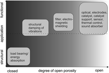 | ||
| Fig. 5 Type of application (structural or functional) in dependence of the porosity of the metal. Adapted with permission from ref. 37, Copyright 2002, Wiley-VCH Verlag GmbH & Co. | ||
Most of the techniques applied nowadays to fabricate such metal sponges are based on using a template structure, which is reproduced. Polymeric sponges (typically prepared from polymeric foams by removal of the cell faces) are often applied as template, either for the preparation of a castable mold (replication e.g., by investment casting) or for the deposition of the metal directly on the polymeric sponge, followed by its removal.1,6,7 During the investment casting process the interconnected open pore space of a polyurethane foam is filled with a ceramic investment compound (Fig. 6a). After burning or melting out the polymer the ceramic structure serves as mold and is infiltrated by the metal melt. After solidification the ceramic mold is removed and the metal foam replicates the structure of the polymer foam. In a similar approach the surface of a polyurethane foam is coated with a thin metal layer (Fig. 6b). Either the polymeric foam is pre-coated by physical vapor deposition (PVD) to make it electrically conductive for the subsequent electroplating of a thick metal layer or the polymeric foam is directly coated with a metal layer by chemical vapor deposition (CVD).7 After removal of the polymer by heat treatment the polymer's structure is also reproduced but the struts are hollow.
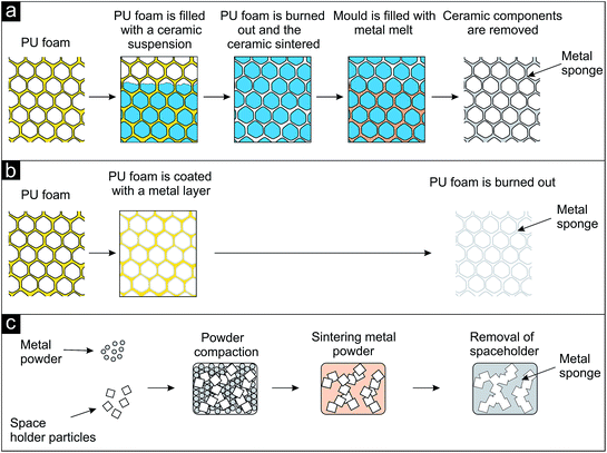 | ||
| Fig. 6 Schematic representation of processes leading to metal sponges (after ref. 1). (a) Investment casting process, (b) coating of a polyurethane sponge with a thin metal layer and subsequent removal of the polymer, (c) sodium chloride as space holder particles, compaction with metal powder, sintering and dissolution. | ||
As an example for a commercially available product prepared by investment casting Duocel® (by ERG Materials and Aerospace Corp.) is shown in Fig. 7a.57 Copper panels are fabricated in dimensions up to approx. 25 mm × 150 mm × 460 mm, aluminium ones up to approx. 100 mm × 350 mm × 400 mm. The aluminium sample in the middle is 40 × 60 mm in size. Fig. 7b displays a porous nickel structure (known as INCOFOAM®) fabricated by depositing the metal onto a polyurethane sponge. After removal of the template an open-cell porosity results, exhibiting a pore space inside the struts, which is revealed in the inset of Fig. 7b.58 When the template material is used in form of individual particles, they are called space holder particles. A lot of different space holders have been applied for the production of porous metals. Sodium chloride, sugar, carbonates, sand or even metals can be named as prominent examples here.1 A schematic illustration of the process using NaCl is given in Fig. 6c and porous titanium as example is shown in Fig. 7c.59
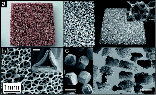 | ||
| Fig. 7 Representative examples of metal sponges prepared by different routes. (a) Open porous metal sheets (Duocel® copper and aluminium, Copyright 2011, ERG Materials and Aerospace Corp.) prepared by the investment casting technique (reproduced with permission from ref. 57, Copyright 2012, Elsevier Ltd.). Inset: structural connectivity (reproduced with permission from ref. 60, Copyright 2012, Wiley-VCH Verlag GmbH & Co.). (b) Open porous metal structure prepared by the deposition of nickel onto a polyurethane foam followed by the removal of the polymer template structure (INCOFOAM®). Inset: pore space inside the struts, which is created after removal of the polymer template, white scale bar: 2 μm (reproduced with permission from ref. 58, Copyright 2004, Wiley-VCH Verlag GmbH & Co.). (c) Open porous titanium prepared by the space holder approach with NaCl crystals (left image) as space holder particles, white scale bars: 400 μm (reproduced with permission from ref. 59, Copyright 2010, Elsevier B.V.). | ||
Independent of the composition of the space holder material, it has to provide a percolating network throughout the body in order to be efficiently removed, thus creating the pores. The space holder technique enables the fabrication of macroscopic bodies with homogenous open-cell porosity and with a controllable average cell size.
Another frequently applied approach involves pressing or sintering of preformed metallic macro-particles like spheres, hollow spheres, fibers or flakes into a macroscopic piece of spongy metal.1,61–64 During the whole process the metal will never reach its molten state. Thermally activated superficial sintering effects like necking at touching faces provide the connectivity among the individual particles. Advances in the preparation of metallic building blocks allow the fabrication of a wide variety of different metal sponges by this method.
In addition to the macroscopic shape of the metal foams and sponges, the nature of the porosity represents another major factor in determining any possible applications. Metal foams with their characteristically closed-cell porosity are mainly found in structural/lightweight, energy absorption and vibrational applications, while metal sponges extend the functionality due to the interconnected pore network, allowing other media such as liquids or gases to pass through the material. Accordingly, metal sponges are promising candidates for electrodes and filters, as catalyst/catalyst supports, and for thermal control, electromagnetic shielding and sound absorber applications (see Fig. 2 and 5).3,37,38,51,65,66
As the scaling of the pore structure features is limited in the case of the discussed industrially applied preparation techniques for metal foams and sponges other fabrication routes were developed mainly with respect to make the pores smaller and to narrow down their size distribution. De-alloying might be the most prominent approach. The process takes advantage of, and is based on, a large enough difference in the electrochemical activity of typically two metals combined in an alloy.1,67–71 Different kinetically and diffusion dominated processes lead to the formation of beautifully entangled and percolating porous metal structures with pores in the range of tens of nanometers after selective dissolution of one of the metals. However, restrictions in the physical processes to small dimensions only allow for the preparation of such nano-spongeous metals in the form of thin films (2D).
Trying to directly influence the geometry of the evolving pores powered the development of sacrificial templating techniques. The principle is the same as in the space holder approach but the templates are of much smaller size, and their shape and arrangement can subtly be controlled. In contrast to the space holder technique sacrificial templating is mostly performed on a lab-scale. Still, nowadays the most widely applied template material is of spherical geometry.72–76 Under specific conditions, these spheres can be densely packed periodically over a long range. The as obtained sacrificial colloidal structure can then be infiltrated either by metal or metal precursors. Also here the technique is mostly limited to reproduce thin films. Besides trying to gain direct control over the pore size, pore size distribution, pore geometry and connectivity research started to focus on the exploration of strategies, which make it possible to prepare very high surface area porous metal structures. The need for such material is strongly promoted by the development in the field of catalysis/catalyst support or electrode applications as the efficiency of such material directly correlates with the amount of active surface or interface (three phase boundary) exposed.
Stimulated by the fascinating properties of aerogels with their ultralow relative densities and high surface areas efforts were undertaken to manufacture similar architectures out of metals.2,77 As the density of metals is much higher compared to silica as the classical aerogel material, the specific surface area is much smaller. Therefore, the measure of the surface area density (or volume specific surface area) in m2/m3 is of more significance. A recent approach developed by Tappan et al.78 is based on combustion synthesis and is able to produce nanoporous metal structures with different compositions. The porous structure obtained resembles those of the metal oxide aerogel counterparts. Indeed, the as prepared nanoporous metals exhibit surface areas in the intermediate range of metal oxide aerogels. Although the process enables the preparation of monolithic samples, their shape is typically limited to simple geometries.
As discussed in this section, many aspects decide on the practical applicability of a porous metal. Accordingly, the major challenge is not just to control the macroscopic shape or the features of the pores, but both of them including the fabrication of porous structures with defined and also complex 3D shapes and the possibility to design the evolving pores at the sub-micrometer range (Fig. 8). Hence, it is the goal of the following sections in this review article to elaborate some of the major production procedures leading to porous metal structures with the focus on their capability of reproducing complex 3D shapes and of providing subtle control over the evolving pore structure. At the same time, a novel process developed in our laboratory for porous copper sponges with tunable relative densities and controllable porosity will be outlined and discussed in the context of the gap existing in the parameter space of the degree of 3D shape complexity versus degree of pore structure controllability (Fig. 8).
3. The importance of the relative density of metal foams in controlling the mechanical properties
In this section we discuss the different fabrication techniques in relation to their abilities to control the porosity in metal foams. The porosity, or the relative density, represents the main parameter governing the mechanical properties and thus determines the potential application field.In the early days of industrial metal foam preparation their applicability in the field of structural/lightweight and energy absorption applications was considered the principal reason justifying their existence. Primarily the metal foam parts were meant to replace existing, more bulky metal parts to reduce the weight of the structure, which can be crucial especially in automotive and aircraft industry. To be considered as possible substitute material improving the overall performance of the structure where it is incorporated three criteria have to be fulfilled. First, the capability of being integrated into existing structures is of major importance. Second, the material index (a key figure describing the performance of a material based on selected properties) for given load conditions has to be high enough (e.g., flexural stiffness to density ratio, tensile strength/stiffness to density ratio, bending strength/stiffness to density ratio etc.). Third, and maybe most importantly, the production has to be realized at low costs.13,37 It is obvious that the chosen manufacturing process determines to which extent these three demands can be met.
Here, we will spot the light on the role of the pore structure of the metal foam in guiding the engineering of the materials indices. The main properties affecting the materials indices are their density, elastic modulus and the elastic collapse stress and, in the case of energy absorption applications, also the onset of the strain at which compaction occurs (compressive strain). Following the mathematical description of the scaling laws, meticulously elaborated by Gibson and Ashby,13 it can easily be concluded that the mechanical deformation behavior is dictated by the inherent structure of the metal foam. Depending on the overall pore volume and corresponding cell wall thicknesses the relative density of the foam is predetermined and thus defines its elastic modulus, elastic collapse stress and compressive strain. For lightweight/structural and energy absorption applications the relative density of the metal foam is therefore the most important property.
A variety of processes were developed to produce metal and metal alloy foams with different densities.4,35,79–91 Depending on the foaming technique a specific pore structure with its related mechanical properties evolves. Fig. 9 shows three examples of aluminium foams with different overall pore volumes and cell wall thicknesses produced by standard foaming processes.13 The different relative densities resulted in different mechanical deformation behaviors. Fig. 9a shows the pore structure of an aluminium foam produced by direct gas injection into the melt (the product is commercially known as Cymat). Among the three samples, it exhibits the lowest relative density of 0.04 (0.108 g cm−3). Fig. 9b shows the structure of an aluminium foam produced by a direct foaming process, where a blowing agent was added to the metallic melt (the product is commercially known as Alporas). The foam's relative density is 0.09 (0.24 g cm−3). Fig. 9c reveals the pore structure of an aluminium foam, which was produced by indirect foaming technique. The foaming agent was incorporated into a solid precursor (the product is commercially known as Alulight). Its relative density is 0.25 (0.435 g cm−3). These technically matured processes allow for the adjustment of the relative density of the foams, even though in a limited range, and thus provide a tool for tuning the deformation behavior of the structure. This is exemplified by the compressive behavior of Alulight foams with different relative densities ranging from 0.22 to 0.44 (Fig. 9d).52 The compressive deformation curve features three characteristic stages, which are common to nearly all metal foams loaded in compression. The first stage describes the predominant elastic deformation behavior, which correlates the stress and strain linearly. A plateau at a nearly constant stress level distinguishes the second stage, where the cells collapse and the foam predominantly deforms plastically by yielding. The third and last stage reveals a strong increase in the stress resulting from the final compression of the contacted opposing cell walls. Although the pore size distribution is not homogeneous, the pore shapes are not regular and cell wall thicknesses are not uniform, the scaling laws proposed by Gibson and Ashby can still be adapted to describe the deformation behavior in dependence of the foams' relative densities. Therefore, the elastic modulus, the elastic collapse stress and the compressive strain of such solid metal foams, as they are used in structural/lightweight and energy absorption applications, scale with the relative density of the foam, which was investigated experimentally and in theory.12,13,39,52,79,92–95
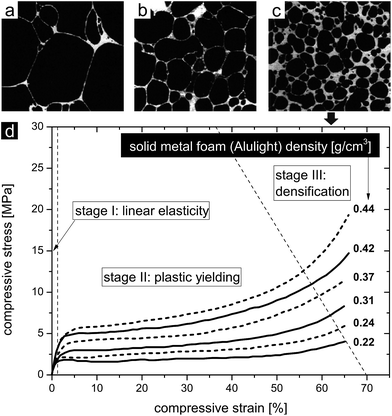 | ||
| Fig. 9 (a) Porous aluminium with a relative density of 0.04 (0.108 g cm−3), (b) porous aluminium with a relative density of 0.09 (0.24 g cm−3), and (c) porous aluminium with a relative density of 0.25 (0.435 g cm−3). (a–c) Reproduced with permission from ref. 13, Copyright 2000, Elsevier Inc. (d) Compressive deformation behavior of aluminium foams with different densities. Reproduced with permission from ref. 52, Copyright 2002, Wiley-VCH Verlag GmbH & Co. | ||
Although the idealized models by Gibson and Ashby correctly describe the mechanical properties of most of the metal foams and sponges, at least qualitatively, more complicated models were also developed, but go beyond this review. How different structural features like strut length and connectivity or inhomogeneous distribution in the size of cross-sectional area along struts can influence the mechanical behavior is described in the literature, e.g., nicely summarized by Goodall and Mortensen.1
Accounting for all the different preparation techniques available and also used in industry nowadays, it can be concluded that by direct, indirect and emulsion mediated methods porous metal structures can be realized with relative densities spanning a large range from 0.02 up to 0.8 and therefore provide porous metals with a wide variety of mechanical deformation behaviors. Given the need to find a compromise between reduction in weight and weakening of the mechanical deformation behavior, the fabrication process has to be selected carefully. The methods and the different design steps are covered in literature.45–49 It is important to note that these industrially applied processes are flexible and also allow for the preparation of complex 3D shapes. The possibility to prepare foams not only from single-phase metals, but also from alloys, greatly affirms their importance in the field of structural and energy absorption applications. The key to tailored properties of metal foams is the control over the connectivity of the cell walls in the struts, the struts' length, the geometry of the struts and cell walls, the shape and size(-distribution) of the cells, the distribution of the material in the struts and cell walls or, in summary, the control over the evolving pore structure of the foam. Therefore, the next section is dedicated to the pore structure control in foams and especially sponges to introduce new functionalities in addition to the mechanical properties.
4. The importance of the pore structure of sponges: control of mechanical and functional properties
In this section we discuss how the transition from closed-cell foams to open-cell sponges opens up new possibilities to combine the mechanical properties with additional functionality. Such a step is only possible, if fabrication techniques are used that allow excellent pore structure control. Accordingly, the traditional foaming methods are often replaced by chemical reactions.Not only the mechanical behavior depends on the relative density of the foams, but also electrical, thermal or acoustic properties.1,13,14,52 The application potential of foams greatly increases, when the foams combine structural characteristics with a functional property. An illustrative example is the usage of metal foam parts in energy absorption applications in automotives, where they additionally act as silencer for efficient damping of noisy sound waves.37 The widening of the field of potential applications for such metal foams due to combination of structural and functional properties was exploited already in the very beginning of the fabrication of metal foams and is still being explored.3,37,38 An important step in this context was the opening of the metal foam structures by omitting cell walls. Open-cell porosity sponges significantly improved the functionality of porous metals (cf.Fig. 5). The percolating, interconnected pores allow the dynamical dispersion of a second phase inside the metal. Either liquids/gases or radiation carrying energy can pass through the pore channels, which directly leads to a dramatic increase in the amount of permanently, from the outside environment, accessible two-phase boundaries inside the structure. Letting a medium flow through the pores of an open-cell metal sponge structure opens up the possibility to use it as a filter,3,29,37,38 catalyst or support for catalyst material,3,37,38,96–98 thermal control element28,29,66 (heat exchanger/cooling device) or flow control device.3,29,99 Depending on the application the degree of open porosity (anything between fully open to partially open) is important for reaching high efficiency (cf.Fig. 5). Independent of the media, which is filtered, either gas or liquid, the open-cell metal sponges serve as mesh retaining particulate solids dispersed in liquids or liquid droplets/solid particles in gases.37 It is obvious that depending on the area of operation given flow rates have to be guaranteed or given particle sizes have to be retained. Such strict requirements can only be met if the resulting metal network structure (e.g., degree of open porosity, cell/window size, cell wall thickness and strut dimensions) can be precisely controlled. Furthermore, these structural features will directly influence the degree of friction (permeability), which counteracts the flow of a medium through the metal network and therefore define the size of the pressure drop across the medium. The engineering of pressure drop is even more important in thermal control applications, for example in heat exchanger/cooling devices. Similar argumentation applies for functional applications of metal sponges as catalysts or catalyst supports. The general idea is to provide a percolating network of metal struts, which either directly provides active surface due to the inherent catalytic activity of the metal itself or can be decorated with catalytically active particles. Depending on the application the active network either catalyzes the degradation of pollutants or harmful substances dispersed in liquids or gases, or classically promotes chemical reactions in industrial production processes. Critical parameter for efficient catalysts is the amount of active interfacial area present between the liquid or gas carrying the substance to be reacted and the catalyst itself. In the language of metal sponges this would translate into high specific surface area densities. But often this directly implicates smaller pore sizes, leading to a parasitic increased pressure-drop across the porous sponge. Therefore, an optimization problem has to be solved in order to reach a high mass transfer coefficient at an acceptable level of excess pressure needed for letting the liquid/gas flow through the catalyst.100 In analogy, control over the metal sponge's pore structure would allow a specific design and lead to an increase in the efficiency in other functional applications like fluid flow control elements, sound absorbers, spargers or scaffolds for tissue and bone regeneration engineering.
Due to the fact that the internal structural elements of many metal sponges and also their connectivity are typically of stochastic nature, it is rather difficult to develop models to accurately describe the pressure drop in such materials. Nevertheless, there are relations available that describe the dependence between pore structure (i.e., porosity and specific surface area) and pressure drop, which, however, go far beyond the scope of this review article and can be found in dedicated literature.28,29,101–103
The trend of miniaturizing all types of functional devices and simultaneously maximizing their efficiency also affected the downscaling of porous metals. To meet this challenge, the connecting elements building up the porous structure need to become smaller, and the geometrical appearance needs to be controlled. The classical foaming methods have been replaced by chemical reactions such as de-alloying.1,67–71 By altering the temperature and chemistry of the process the evolving pore structure concerning strut/ligament and pore/void dimensions can be influenced (Fig. 10).69,104,105 Au–Ag, Au–Cu, and Au–Al2 are the most prominent alloys used to fabricate nanoporous gold.68,69,71,104,106–108 Furthermore, Ni–Al, Cu–Mn, Cu–Zn, Cu–Al2, Cu–Mg and Pt–Cu represent the alloys forming nanoporous Ni,109,110 Cu70,111–114 and Pt115 after selective dissolution of the less noble metal. The as fabricated nanoporous metals can be described as a uniform interpenetrating solid–void composite with a narrow and controllable void/ligament size distribution (Fig. 10).
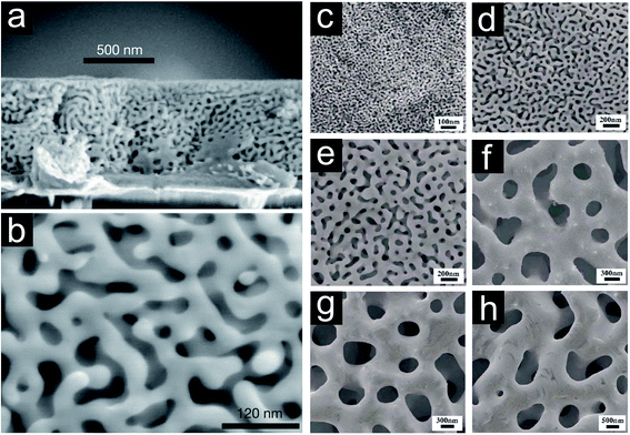 | ||
| Fig. 10 (a) Scanning electron micrograph of cross-sectional view of de-alloyed Ag–Au thin film. (b) Plane view of de-alloyed Ag–Au thin film revealing ligament spacings in the order of 10 nm. Reproduced with permission from ref. 69, Copyright 2001, Nature Publishing Group. Evolving pore structure of nanoporous gold film by treating Ag–Au films: (c) de-alloyed for 5 minutes at room temperature (RT), (d) de-alloyed for 48 hours at RT, (e) thoroughly rinsed and annealed at 200 °C for 2 hours, (f) thoroughly rinsed and annealed at 400 °C for 2 hours, (g) thoroughly rinsed and annealed at 500 °C for 2 hours, (h) thoroughly rinsed and annealed at 600 °C for 2 hours. Reproduced with permission from ref. 105, Copyright 2007, AIP Publishing LLC. | ||
Inspired by colloid chemistry, the idea of using metal nanoparticles as building blocks, followed by their assembly into three dimensionally interconnected networks was born. In a first step, a gel has to be prepared where the metallic building blocks fill a volume space by connecting each other to a percolating network structure, whose pores are filled by a solvent. In a second step, this gel is subjected to supercritical or freeze drying to replace the liquid in the pores with air in absence of disruptive capillary forces. As produced aerogel structures characteristically consist of struts/ligaments made up of the connected building blocks in a necklace-like appearance defining pores of tens of nanometer size and highly irregular geometry (Fig. 11a–d). A recently published work by Liu et al.116 presents an interesting approach for the production of even bi-metallic nanoporous metals, without supercritical drying, in order to reproduce such “aerogel-like” architectures (Fig. 11e and f). These structures show great promise towards the preparation of nanoporous metals exhibiting very high specific surface areas, measured as area per unit mass.
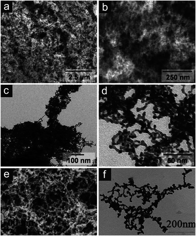 | ||
| Fig. 11 Metallic aerogel and “aerogel-like” structures. (a and b) Scanning electron and (c and d) transmission electron micrographs of platinum aerogels. Reproduced with permission from ref. 77, Copyright 2009, Wiley-VCH Verlag GmbH & Co. (e and f) Scanning electron and transmission electron micrographs of gold–platinum bimetallic porous structures. Reproduced with permission from ref. 116, Copyright 2011, Centre National de la Recherche Scientifique (CNRS) and The Royal Society of Chemistry. | ||
Up to now it seems impossible to gain precise control over the evolving pore structure as e.g. in the process of de-alloying. An alternative approach to the direct assembly of nanometric metallic building blocks is the nanosmelting technique. Instead of preparing a gel from the metallic building blocks hybrid polymer–metal oxide gels are prepared and subsequently supercritically dried. The resulting polymer–metal oxide aerogels are then pyrolised under inert atmosphere meanwhile products from the decomposition of the polymer reduce the metal oxide to a metallic network. Examples of metals forming stable metal oxide networks with the ability to be reduced to metal aerogels by pyrolysis are Fe, Co, Ni, Cu and Sn.78,117,118 In contrast to the direct assembly approach the heat treatment step renders it rather difficult to gain control over the evolving pore structure, particularly due to associated volume changes and cracking of the material.
Another highly flexible approach was developed by Tappan et al.78,119 and relies on the principles of combustion synthesis. The energetic precursor materials are metal complexes containing the ligand bistetrazolamine and are pressed into pellets, which are ignited under inert atmosphere. During the combustion process the metal atoms in the complex are reduced to their zero oxidation state and released to agglomerate into nanometer-sized grains. The subsequent assembly of these nanometer-sized grains into struts is governed by the expansion of the evolving N2 gas. A list of nanoporous metals prepared via combustion synthesis is long and includes technologically important metals like Fe, Co, Ni, Cu, Ag, Au, Pd, Pt and Ti.78,119,120 As prepared nanoporous metal structures consist of pores in the size range of a few nanometers up to several micrometers and struts made up of nano-sized grains or assemblies thereof. The structures exhibit very high specific surface areas, but subtle control over the porous structure over several length scales seems nearly impossible at this stage even though combinatorial approaches to overcome this limitation are being explored.120
The highest control over the pore structure should, in principle, be achieved by a sacrificial template assisted technique. Ideally, the hard or soft templates define by their size, shape, morphology and connectivity the nature of the pores in the metal network after removal of the template. Advances in the synthesis of colloidal silica or polystyrene made it possible to use them as template materials.74–76,121 They are monodisperse, their surface chemistry can easily be tuned and they can be arranged into highly regular opal structures. In a subsequent step, the voids within the template particles are infiltrated by either the metal precursors or by the metal nanoparticles. In the case of precursors, they are then chemically reduced to form the solid metal. In a last step, the template is removed in order to create the open porous structure. Besides colloidal silica or polystyrene spheres representing hard templates also other templates (natural materials, soft templates…) are used in order to gain control over the evolving pore structure of the porous metal. A nice overview on the fabrication strategies and applications of nanoporous metals is given by Zhang et al.121 Various metals like Au, Pt, Ni, Cu, Ag and Co have been brought into nanoporous configurations by templating opal structures as described above.73,122,123 These inverse opals characteristically show high structural order with periodically repeating unit cell character over long ranges in two dimensions. The struts are sharply defined and directly reproduce the geometry of the corresponding pores in the colloidal template (Fig. 12).
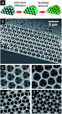 | ||
| Fig. 12 (a) Schematic of sacrificial template assisted technique. Reproduced with permission from ref. 76, Copyright 2008, American Chemical Society. (b) SEM of nickel inverse opal structure forming a film. (c–f) SEM of nickel inverse opal structures exemplifying the possibility to trigger the window size (and cell wall resp. strut thicknesses) by adjusting the corresponding etching time. Reproduced with permission from ref. 124, Copyright 2007, Wiley-VCH Verlag GmbH & Co. | ||
Besides the five principal directions (de-alloying, assembly of nano-sized metallic building blocks into aerogels, nanosmelting, combustion synthesis and templating procedures) just very briefly summarized before, other less common approaches have been elaborated and are still being discovered.125–127 The research is pushed by the enormous potential of nanoporous metals to increase the functional efficiency of catalysts, sensors, fuel cells or batteries. Yuan et al.128 summarized in their thoroughly elaborated review the different possible functions, which could be taken over by porous metals integrated in polymer electrolyte membrane fuel cells. Acting as flow field, properties like homogeneous reactant distribution and high mass transfer are critical parameters, which need to be addressed in the design. Finding application as current collector, the optimization of the porous metal's electrical conductivity would be of principle interest. Serving as catalyst support, primarily a high amount of specific surface area would lead to an increased efficiency of the fuel cell. Furthermore, high thermal conductivity and mechanical stability would lead to an improved thermal management and provide structural support of the membrane electrode assembly respectively. Yuan et al.128 furthermore concluded that besides mono-functional integration of porous metal structures they can simultaneously be used for multifunctional purposes, e.g., flow field, diffusion medium and catalyst support. In a different work, Zhang et al.26 used inverse Ni opal structures for the design of a bicontinuous battery cathode (Fig. 13a–e). The Ni framework served as current collector and was decorated with the corresponding electrochemically active species. The specific design of the inverse opal structure, characterized by the high porosity, uniform pore dimensions and large specific surface area, together with the high electrical conductivity of metallic nickel lead to the situation that the four mentioned primary resistances (Fig. 13b) during battery charge and discharge could effectively be minimized. Owing to the tailored design of the cathode, ultrafast charge and discharge properties were achieved. However, it also has to be mentioned that the proposed setup is not practical for real batteries as the Ni framework introduces extra inactive weight, which reduces the volumetric and gravimetric energy density. A completely different field of functional applications, governed by the optical properties of porous metals, can experimentally be conquered due to the possibility of preparing highly uniform/homogeneous or quasi periodic porous metal structures, e.g. by the afore mentioned de-alloying technique or sacrificial template method leading to inverse opals.
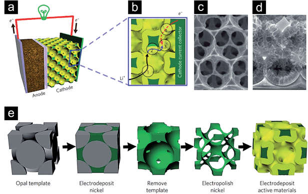 | ||
| Fig. 13 (a) Schematic of a battery setup with a bicontinuous cathode. (b) Illustration of the four primary resistances determining the overall efficiency during cycling of a battery element: (1) a rapid ion transport in the electrolyte is crucial; (2) the solid-phase ion diffusion length has to be short; (3) the area where the electrochemical reactions take place in the electrode has to be large; (4) a high electron conduction in the electrode/current collector assembly has to be guaranteed. (c) Scanning electron micrograph of the electropolished nickel structure. (d) Structure after the electrodeposition of the active material. (e) Schematic of the process leading to the bicontinuous electrode. Reproduced with permission from ref. 26, Copyright 2011, Nature Publishing Group. | ||
Biener et al.104 investigated in their work de-alloyed nanoporous gold structures, whose pore sizes could be fine-adjusted by a simple post-synthetical heat treatment step. They found that the surface enhanced Raman scattering enhancement factor27 could be optimized by adjusting the average pore size. In the work of Yu et al.124 it was shown that the optical properties (in terms of absorption and thermal emission) of the inverse Ni opals significantly change depending on the degree of openness of the structure, which was increased by increasing the window size between the adjacent spherical pores. They related this change of optical properties to the increased penetration depth of the light into the material, leading to a rigorous decrease in the contribution of surface effects and increase in the contribution of 3D periodicity to the optical behavior. In both cases the subtle fine-tuning of the resulting porous metal architecture is of tremendous and essential importance in order to find application as plasmonic nano-sensors or material for surface enhanced Raman spectroscopy.129
As briefly pictured in this section, opening up of metal foams leading to open-cell porous metal structures creates a new field of functional applications (see Fig. 5). The porous metal structure has to be tailored e.g. for adjusting permeability and form coefficients, for exhibiting uniform and/or periodical porosity with defined pore sizes, for providing high amount of specific surface area or for high electrical and thermal conductivities. The actual potential of functional porous metals is even further exploited when simultaneous optimization of several afore mentioned properties are required by a given application.
Independent of whether a metal exhibits open or closed-cell porosity, a third critical parameter, in addition to relative density and pore structure, is the macroscopic shape of a metallic body in determining the function and the application of the material. Accordingly, state-of-the-art fabrication techniques have to be able to provide control over several orders of length scales from the nano-/micrometer range up to a macroscopic level. In the following section, we will discuss these issues.
5. The importance of shape: from pore structure to shape control
In this section we discuss the importance of the macroscopic shape of the porous metallic body for the functionality – in addition to the composition and the pore structure. Control from the nano- or micrometer range up to macroscopic dimensions makes highest demands on the fabrication method.Highly important concerning the use of porous metals in applications is the fact that many of the techniques described above show a great flexibility regarding the choice of the composition including not only metals but also alloys. Furthermore, many of the approaches allow for quite subtle control over the pore structure of the foam or spongy material including pore size, structural uniformity/periodicity, specific surface area, relative density and cell wall/strut/ligament dimension, shape and connectivity. Consequently, two of the three most important criteria (i.e., composition and pore structure), as mentioned in the introduction, qualifying such structures for their applicability are already quite successfully and extensively met. A third critical parameter, which still often represents a considerable challenge, is the macroscopic shape.
In many cases, the porous metals are not intended to be used as stand-alone body. In fact, they need to be integrated into preformed structures or combined with other pre-assembled materials or devices. In the case of metal foams, which are often used in structural load bearing and energy absorption applications, it is crucial that they can be produced in large geometries, e.g., large sandwich panels or as filling material for extruded profiles. However, depending on the functional application, it is not always required to produce larger parts. On the contrary, it is more important to produce smaller structures, but with complex geometries. For example, silencers for the damping of sound waves, pressure pulses or mechanical vibrations preferentially exhibit more complex three-dimensional shapes, which, depending on the field of application, have to be even miniaturized. For biomedical implants it is particularly important to be able to precisely produce three dimensionally complex shapes and geometries. As catalyst support or flow field in fuel cells the porous metal has to be brought into three dimensional configurations compatible with the membrane electrode assembly. Similarly, porous metals acting as filter material need to be shaped into specific geometries in order to execute their function inside tubes or channels. Furthermore, the promising field of heat exchanger and cooling device applications is based on contacting the corresponding part, which needs to experience a change in temperature, with the porous metal structure. Especially in microelectronics, where the integration density in chip structures constantly increases, passive cooling takes an important place, as only highly efficient heat removal guarantees reliable operation of the device. To serve this purpose the porous metal needs to be produced in small and also complex three-dimensional geometries. This short list points out the importance of the flexibility of an approach towards the synthesis of different, also complex three-dimensional shapes.
We believe that the development of preparation techniques simultaneously serving all the three major demands, namely, being flexible in producing a wide compositional variety of different porous metals/alloys, allowing subtle control over the evolving pore structure and providing the possibility to produce also complex three-dimensional shapes, will greatly contribute to the application of porous metals not only in niche but also in mass markets. Therefore, we now discuss the previously introduced preparation routes according to their abilities to produce porous metals with complex, 3-dimensional and macroscopic shapes.
De-alloying and colloidal-crystal-templating are basically limited to 2D geometries like films or coatings. It is extremely challenging to achieve long-range order over 3 dimensions.
Among the other techniques, which in principle allow for the preparation of macroscopic 3D architectures with complex shapes, the direct and indirect foaming techniques together with emulsion/wet foam-mediated approaches are the most flexible ones. In case of the direct and indirect foaming procedures the main drawback is the limited control over the evolving pore structure. Nevertheless, recent developments show significant progress to overcome this limitation.41–44,50
For metal sponges with their open-cell porosity the investment casting and space holder techniques are able to produce interconnected network structures also with complex 3D geometries. The space holder approach is not only able to produce macroscopic 3D sponges, but shows the highest potential for directly controlling the resulting pore structure through replication of the space holder material. Limitations include the production of large geometries, because the complete removal of the space holder material can still be difficult due to long diffusion pathways. The technique of sintering and compacting macroscopic metallic building blocks (e.g., particles, fibers, hollow spheres) is flexible and holds the great advantage of the comparably easy reproduction of larger parts with complex geometries. However, the direct control over the pore structure of such sintered or compacted sponges is highly limited. As a conclusion, all these techniques are widely technologically applied, but the individual processes typically do not allow both pore structure and macroscopic geometrical control. Furthermore, it is difficult to reach low relative densities with these techniques. The preparation of large structures with subtle control over the resulting pore structure spanning several length scales remains challenging.130 Other techniques like combustion synthesis, nanosmelting or the assembly of metallic nanostructures lack the possibility to precisely control the resulting shape of the body as well as to achieve pore structure control. Newly developed strategies have to ideally give access to porous metal structures with low relative densities, provide excellent pore structure control and enable processing of the macroscopic body into complex shapes. These requirements can best be fulfilled by applying wet-chemistry approaches, where the transformation of molecular precursors to the final material can be controlled on a size scale ranging from an atomistic level to macroscopic dimensions. In the next section, we will elaborate such a strategy developed in our group.
6. Colloidal routes to macroscopic copper sponges
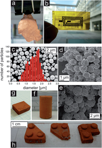
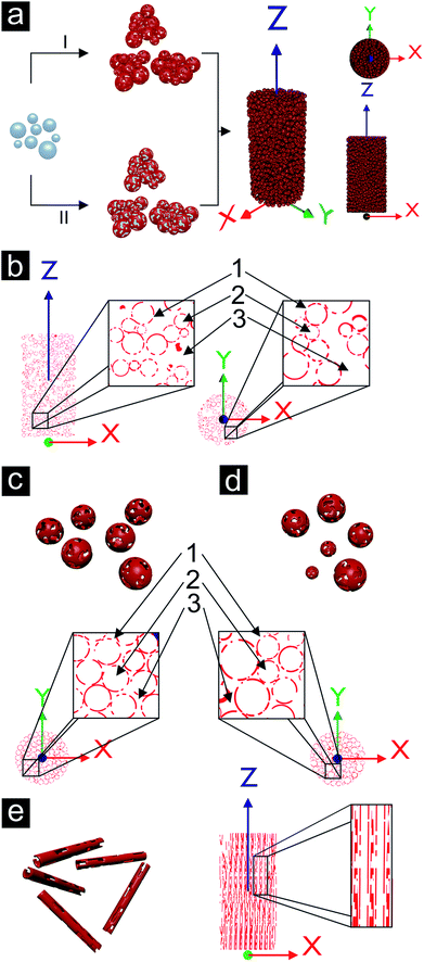
A template-assisted solution route seems to be best suited to address the demand for controlling the pore structure of the porous metal. Such a LEGO approach, i.e., the fabrication of building blocks, which can be precisely arranged and connected with each other, holds great potential for producing macroscopic materials with complex shapes. As a matter of fact, such building block approaches have extensively been used in nanoparticle research (although the step from nanoscale to macroscopic dimensions remains a serious issue),130–133 but are rather unexplored for metallization processes mainly due to the difficulty to grow metal layers on three-dimensional template particles by wet chemistry. Recently, we reported a wet-chemical and catalyst-free electroless deposition process for copper by reacting copper(II) acetylacetonate (Cu(acac)2) with benzyl alcohol (BnOH).134 The obtained free-standing copper foils represent, to the best of our knowledge, the first macroscopic metallic structures prepared by the benzyl alcohol route (Fig. 14a), which has been extensively used for the synthesis of metal oxide nanoparticles.135 After complete delamination of the copper film from the wall of the reaction vessel macroscopic pieces could be isolated. The pore structure revealed a broad grain size distribution (50 nm up to 1 μm) and the connectivity between the grains is strong enough so that the foil can be handled by tweezers. The deposition of the copper not only occurred on the surface of the reaction vessel, but also on polymer substrates immersed in the reaction solution, e.g., on top of a flexible Kapton substrate (Fig. 14b). For such experiments the substrate was placed inside the reaction solution under a slightly tilted angle, as it is also described by Ilari et al. for the growth of copper on supported carbon nanotubes.136 Obviously, the copper deposition process is suitable for coating different kinds of surfaces. As a matter of fact, it is even possible to coat 3D objects like, e.g., spherical, micrometer sized ZnO particles (Fig. 14c).137 The ZnO particles were dispersed in BnOH, Cu(acac)2 was added and the mixture heated at 180 °C. A porous layer of metallic copper grew on the surface of the ZnO particles (Fig. 14d). Starting with these copper coated ZnO particles as building blocks, in principle two strategies can be envisioned (Fig. 15a). Either the powder is taken and processed into the desired shape followed by the removal of the template spheres from the assembled macroscopic body (Fig. 15a, pathway II), or the template spheres are first removed leading to new building blocks being porous hollow copper spheres (Fig. 15a, pathway I, and Fig. 14e), which can subsequently be brought into a given macroscopic, three dimensional shape. Having the building blocks available in the form of a powder opens up the possibilities to use well-established slip casting procedures for reproducing macroscopically also complex 3D shapes (Fig. 14f–h).138 It is important to mention that typically the copper coated ZnO spheres as well as the porous copper capsules are prone to agglomeration, forming clusters rather than individual particles.The bodies were found to be electrically conductive. They show some degree of mechanical load capacity and can be produced with different relative densities (ranging from 7 to 21%) depending on the degree of compaction of the building blocks. Furthermore, the porous copper structures show a high surface area density of 2 × 10⁶ m2/m3, which exceeds the ones of large scale produced metal sponges by a factor of 100.28,29,139
The copper sponge structures exhibit open porosity on three different levels. The smallest pores inside the copper shells represent the first level of porosity. The second level of porosity is the one defined by the sacrificial template material, in this case by the ZnO particles with their diameters in the size range of about 1 μm. On the third level, pores appear as a result of the gap between the clusters. The three levels of porosity present in a cylindrically shaped copper sponge are schematically summarized in Fig. 15b. 1, 2 and 3 refer to three different levels of porosity, where the size of the corresponding pores increases with increasing number. The clustering of the building blocks represents a problem for the homogeneity of the sample. Individual, well separated copper capsules could be packed in a denser way, which is exemplified in the schemes for monodisperse (Fig. 15c) and polydisperse porous shells (Fig. 15d).
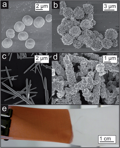
Such template approaches offer a relatively simple tool to tailor the shape of the pores. By substituting the spherical templates by rods anisotropic porosity would be accessible. If the orientation of the coated template rods or needles could be controlled, then directional material properties related to the orientation of the pores inside the copper sponge would be expected (see Fig. 15e). First experiments in this direction are shown in Fig. 16a–d, where other template particles were coated either with a dense or with a porous copper layer. Even polymers, which are usually known to be rather inert like Teflon, can be coated (Fig. 16e).
Clearly, a narrow size and shape distribution of the template particles, together with an agglomeration-free dispersibility, contribute to the regularity of the pore structure in a porous copper sponge, resulting in a more homogeneous material. However, there are three other important parameters that have to be further improved to take full advantage of this synthesis method. The growth of the copper layer, especially in terms of thickness and adherence to the substrate, is not yet fully controllable, but represents one of the main parameters for tuning the functional and mechanical properties. Second, the building blocks have to be arranged with respect to each other by higher precision to yield not only homogeneous structural features, but also gradient-like structural and functional properties in the final porous copper sponge. Third, the shaping has to be extended into much larger size scale, mainly to reliably measure macroscopic functional properties (e.g. fluid flow or heat transfer). In parallel to the improvement of this process, the fabrication of metal structures with different elemental compositions has to be explored. If these issues can be addressed, this template-directed wet-chemical approach will be able to span a maximum range in the parameter space of pore structure controllability and 3D shape complexity as indicated in Fig. 8.
7. Conclusion
Porous metals are typically categorized according to their pore connectivity, i.e., open-cell pores (sponges) and closed-cell pores (foams). Although this parameter represents an important aspect of porous metals, additional features like relative density, pore structure and macroscopic shape are also critical in determining the functionality of porous metals and thus their application potential beyond structural materials. To be able to address all these issues, traditional manufacturing routes have to be optimized and extended, and new synthesis methods have to be developed, allowing control from the nm to the macroscopic dimensions and thus covering several orders of length scales. Like in other fields of materials science,130 wet-chemical routes in combination with traditional methods are able to fulfill many of the requirements. In this context, we discussed the preparation of macroscopically sized copper sponges in more details, which makes use of a template-assisted, electroless deposition approach with traditionally employed slip-casting. Without any doubts, solution routes to metals provide an unprecedented level of synthesis control, which enables complex and sophisticated architectures with new functionalities and thus greatly extended application potential.Acknowledgements
We gratefully acknowledge financial support by ETH Zürich (ETH-05 12-2).References
- R. Goodall and A. Mortensen, in Physical Metallurgy, ed. D. E. Laughlin and K. Hono, Elsevier, Oxford, 5th edn, 2014, pp. 2399–2595 Search PubMed.
- Y. Tang, K. L. Yeo, Y. Chen, L. W. Yap, W. Xiong and W. Cheng, J. Mater. Chem. A, 2013, 1, 6723–6726 CAS.
- J. Banhart, Prog. Mater. Sci., 2001, 46, 559–632 CrossRef CAS.
- J. Banhart, Adv. Eng. Mater., 2013, 15, 82–111 CrossRef CAS.
- J. Banhart, JOM, 2000, 52, 22–27 CrossRef CAS PubMed.
- Y. Conde, J. F. Despois, R. Goodall, A. Marmottant, L. Salvo, C. San Marchi and A. Mortensen, Adv. Eng. Mater., 2006, 8, 795–803 CrossRef CAS.
- J. Baumeister and J. Weise, in Metal Foams: Fundamentals and Applications, ed. N. Dukhan, DEStech Publications, Inc., Lancaster, Pennsylvania U.S.A., 2013, pp. 1–30 Search PubMed.
- J. Banhart, Adv. Eng. Mater., 2006, 8, 781–794 CrossRef CAS.
- M. F. Ashby, Philos. Trans. R. Soc., A, 2006, 364, 15–30 CrossRef CAS PubMed.
- F. Simancik, in Handbook of Cellular Metals, Wiley-VCH Verlag GmbH & Co. KGaA, 2003, pp. 1–4 Search PubMed.
- H. P. Degischer, C. Körner, R. F. Singer, J. Banhart, F. Baumgärtner, G. Rausch, M. Arnold, M. Thies, C. San Marchi, A. Mortensen, O. Andersen and G. Stephani, in Handbook of Cellular Metals, Wiley-VCH Verlag GmbH & Co. KGaA, 2003, pp. 5–70 Search PubMed.
- L. J. Gibson, Annu. Rev. Mater. Sci., 2000, 30, 191–227 CrossRef CAS.
- M. F. Ashby, A. G. Evans, N. A. Fleck, L. J. Gibson, J. W. Hutchinson and H. N. G. Wadley, Metal Foams: A Design Guide, Butterworth Heinemann, Woburn, 2000 Search PubMed.
- L. J. Gibson and M. F. Ashby, Cellular Solids: Structure and Properties, Cambridge University Press, Cambridge, U.K., 2nd edn, 1997 Search PubMed.
- Y.-J. Lee and K. B. Yoon, Microporous Mesoporous Mater., 2006, 88, 176–186 CrossRef CAS PubMed.
- M. D. M. Innocentini, R. K. Faleiros, R. Pisani Jr, I. Thijs, J. Luyten and S. Mullens, J. Porous Mater., 2010, 17, 615–627 CrossRef CAS.
- W. Azzi, W. L. Roberts and A. Rabiei, Mater. Des., 2007, 28, 569–574 CrossRef PubMed.
- R. Singh, P. D. Lee, T. C. Lindley, R. J. Dashwood, E. Ferrie and T. Imwinkelried, Acta Biomater., 2009, 5, 477–487 CrossRef CAS PubMed.
- S. J. Hollister, Nat. Mater., 2005, 4, 518–524 CrossRef CAS PubMed.
- S. Fujibayashi, M. Neo, H.-M. Kim, T. Kokubo and T. Nakamura, Biomaterials, 2004, 25, 443–450 CrossRef CAS.
- H. Chen, C. Wang, X. Zhu, K. Zhang, Y. Fan and X. Zhang, Mater. Sci. Eng., C, 2014, 43, 182–188 CrossRef CAS PubMed.
- H.-H. Huang, C.-P. Wu, Y.-S. Sun, W.-E. Yang and T.-H. Lee, J. Alloys Compd., 2014, 615(suppl. 1), S648–S654 CrossRef CAS PubMed.
- X.-H. Han, Q. Wang, Y.-G. Park, C. T'Joen, A. Sommers and A. Jacobi, Heat Transfer Eng., 2012, 33, 991–1009 CrossRef CAS.
- G. Benedik, B. Širok, M. Eberlinc and M. Hočevar, Forsch. Ingenieurwes., 2011, 75, 243–256 CrossRef PubMed.
- C. Hutter, D. Büchi, V. Zuber and P. Rudolf von Rohr, Chem. Eng. Sci., 2011, 66, 3806–3814 CrossRef CAS PubMed.
- H. Zhang, X. Yu and P. V. Braun, Nat. Nanotechnol., 2011, 6, 277–281 CrossRef CAS PubMed.
- E. C. Le Ru, E. Blackie, M. Meyer and P. G. Etchegoin, J. Phys. Chem. C, 2007, 111, 13794–13803 CAS.
- K. Boomsma, D. Poulikakos and F. Zwick, Mech. Mater., 2003, 35, 1161–1176 CrossRef PubMed.
- K. Boomsma and D. Poulikakos, J. Fluids Eng., 2002, 124, 263–272 CrossRef CAS.
- S. Sen, D. Liu and G. T. R. Palmore, ACS Catal., 2014, 4, 3091–3095 CrossRef CAS.
- Q. Lu, J. Rosen and F. Jiao, ChemCatChem, 2015, 7, 38–47 CrossRef CAS.
- K. Heim, G. S. V. Kumar, F. Garcia-Moreno, I. Manke and J. Banhart, Colloids Surf., A, 2013, 438, 85–92 CrossRef CAS PubMed.
- C. Körner, M. Arnold and R. F. Singer, Mater. Sci. Eng., A, 2005, 396, 28–40 CrossRef PubMed.
- S. Asavavisithchai and R. Kennedy Andrew, in High Temperature Materials and Processes, 2011, vol. 30, pp. 113–120 Search PubMed.
- V. I. Shapovalov and L. Boyko, Adv. Eng. Mater., 2004, 6, 407–410 CrossRef CAS.
- J. Banhart and H.-W. Seeliger, Adv. Eng. Mater., 2012, 14, 1082–1087 CrossRef CAS.
- C. Haberling, J. Banhart, T. Hipke, R. Neugebauer, R. Kretz, E. M. A. Maine and M. F. Ashby, in Handbook of Cellular Metals, Wiley-VCH Verlag GmbH & Co. KGaA, 2003, pp. 299–354 Search PubMed.
- A. G. Evans, J. W. Hutchinson and M. F. Ashby, Prog. Mater. Sci., 1998, 43, 171–221 CrossRef CAS.
- S. Shahbeyk, in Metal Foams: Fundamentals and Applications, ed. N. Dukhan, DEStech Publications, Inc., Lancaster, Pennsylvania U.S.A., 2013, pp. 131–216 Search PubMed.
- L. P. Lefebvre, in Metal Foams: Fundamentals and Applications, ed. N. Dukhan, DEStech Publications, Inc., Lancaster, Pennsylvania U.S.A., 2013, pp. 317–362 Search PubMed.
- M. Mukherjee, F. Garcia-Moreno, C. Jiménez and J. Banhart, Adv. Eng. Mater., 2010, 12, 472–477 CrossRef CAS.
- F. García-Moreno, M. Mukherjee, E. Solórzano and J. Banhart, Int. J. Mater. Res., 2010, 101, 1134–1139 CrossRef.
- N. Babcsan, S. Beke, P. Makk, G. Szamel and C. Kadar, Procedia Mater. Sci., 2014, 4, 127–132 CrossRef PubMed.
- G. S. Vinod Kumar, M. Mukherjee, F. Garcia-Moreno and J. Banhart, Metall. Mater. Trans. A, 2013, 44, 419–426 CrossRef CAS PubMed.
- F. Simancik, M. C. Hahn, R. Braune, A. Otto, T. Bernard, H. W. Bergmann, C. Körner, F. Heinrich, R. F. Singer, J. Banhart, W. Seeliger and C. Beichelt, in Handbook of Cellular Metals, Wiley-VCH Verlag GmbH & Co. KGaA, 2003, pp. 71–125 Search PubMed.
- M. Seitzberger, F. G. Rammerstorfer, R. Gradinger, H. P. Degischer, M. Blaimschein and C. Walch, Int. J. Solids Struct., 2000, 37, 4125–4147 CrossRef.
- S. Santosa and T. Wierzbicki, Comput. Struct., 1998, 68, 343–367 CrossRef.
- S. P. Santosa, T. Wierzbicki, A. G. Hanssen and M. Langseth, Int. J. Impact Eng., 2000, 24, 509–534 CrossRef.
- A. G. Hanssen, M. Langseth and O. S. Hopperstad, Int. J. Mech. Sci., 1999, 41, 967–993 CrossRef.
- C. Körner, Integral Foam Molding of Light Metals: Technology, Foam Physics and Foam Simulation, Springer Berlin Heidelberg, 2008 Search PubMed.
- A. R. Studart, A. Nelson, B. Iwanovsky, M. Kotyrba, A. A. Kundig, F. H. Dalla Torre, U. T. Gonzenbach, L. J. Gauckler and J. F. Löffler, J. Mater. Chem., 2012, 22, 820–823 RSC.
- R. Pippan, C. Motz, B. Kriszt, B. Zettl, H. Mayer, S. Stanzl-Tschegg, F. Simancik and J. Kovacik, in Handbook of Cellular Metals, Wiley-VCH Verlag GmbH & Co. KGaA, 2003, pp. 179–241 Search PubMed.
- C. Körner, in Integral Foam Molding of Light Metals, Springer Berlin Heidelberg, 2008, pp. 45–72 Search PubMed.
- J. Hohlfeld, C. Hannemann, R. Vogel, T. Hipke and R. Neugebauer, Prod. Eng., 2011, 5, 25–30 CrossRef PubMed.
- R. Neugebauer and T. Hipke, Adv. Eng. Mater., 2006, 8, 858–863 CrossRef CAS.
- C. Perrot, F. Chevillotte, L. Jaouen and M. T. Hoang, in Metal Foams: Fundamentals and Applications, ed. N. Dukhan, DEStech Publications, Inc., Lancaster, Pennsylvania U.S.A., 2013, pp. 285–316 Search PubMed.
- P. J. Tan, S. R. Reid and J. J. Harrigan, Int. J. Solids Struct., 2012, 49, 2744–2753 CrossRef CAS PubMed.
- V. Paserin, S. Marcuson, J. Shu and D. S. Wilkinson, Adv. Eng. Mater., 2004, 6, 454–459 CrossRef CAS.
- B. Ye and D. C. Dunand, Mater. Sci. Eng., A, 2010, 528, 691–697 CrossRef PubMed.
- T. Guillén, A. Ohrndorf, G. Tozzi, J. Tong and H.-J. Christ, Adv. Eng. Mater., 2012, 14, B199–B207 CrossRef.
- J. Qiao, Z. Xi, H. Tang, J. Wang and J. Zhu, Mater. Des., 2009, 30, 2737–2740 CrossRef CAS PubMed.
- W. Zhou, Y. Tang, R. Song, L. Jiang, K. S. Hui and K. N. Hui, Mater. Des., 2012, 37, 161–165 CrossRef CAS PubMed.
- K. C. Leong, C. Y. Liu and G. Q. Lu, J. Porous Mater., 1997, 4, 303–308 CrossRef CAS.
- N. Lippitz, J. Rösler and B. Hinze, Metals, 2013, 3, 150–158 CrossRef CAS PubMed.
- P. Colombo and H. P. Degischer, Mater. Sci. Technol., 2010, 26, 1145–1158 CrossRef CAS PubMed.
- C. Y. Zhao, Int. J. Heat Mass Transfer, 2012, 55, 3618–3632 CrossRef CAS PubMed.
- J. Erlebacher and R. Seshadri, MRS Bull., 2009, 34, 561–568 CrossRef CAS.
- J. Erlebacher, J. Electrochem. Soc., 2004, 151, C614–C626 CrossRef CAS PubMed.
- J. Erlebacher, M. J. Aziz, A. Karma, N. Dimitrov and K. Sieradzki, Nature, 2001, 410, 450–453 CrossRef CAS PubMed.
- J. R. Hayes, A. M. Hodge, J. Biener, A. V. Hamza and K. Sieradzki, J. Mater. Res., 2006, 21, 2611–2616 CrossRef CAS.
- Y. Ding and J. Erlebacher, J. Am. Chem. Soc., 2003, 125, 7772–7773 CrossRef CAS PubMed.
- M. Nishizawa, V. P. Menon and C. R. Martin, Science, 1995, 268, 700–702 CrossRef CAS PubMed.
- P. Jiang, J. Cizeron, J. F. Bertone and V. L. Colvin, J. Am. Chem. Soc., 1999, 121, 7957–7958 CrossRef CAS.
- A. Thomas, F. Goettmann and M. Antonietti, Chem. Mater., 2008, 20, 738–755 CrossRef CAS.
- Z.-Z. Gu, H. Chen, S. Zhang, L. Sun, Z. Xie and Y. Ge, Colloids Surf., A, 2007, 302, 312–319 CrossRef CAS PubMed.
- A. Stein, F. Li and N. R. Denny, Chem. Mater., 2007, 20, 649–666 CrossRef.
- N. C. Bigall, A.-K. Herrmann, M. Vogel, M. Rose, P. Simon, W. Carrillo-Cabrera, D. Dorfs, S. Kaskel, N. Gaponik and A. Eychmüller, Angew. Chem., Int. Ed., 2009, 48, 9731–9734 CrossRef CAS PubMed.
- B. C. Tappan, S. A. Steiner and E. P. Luther, Angew. Chem., Int. Ed., 2010, 49, 4544–4565 CrossRef CAS PubMed.
- T. Miyoshi, M. Itoh, S. Akiyama and A. Kitahara, Adv. Eng. Mater., 2000, 2, 179–183 CrossRef CAS.
- S. Akiyama, H. Ueno, K. Imagawa, A. Kitahara, S. Nagata, K. Morimoto, T. Nishikawa and M. Itoh, Foamed metal and method of producing same, US Pat. 4,713,277, 1987, 1986.
- S. Akiyama, H. Ueno, K. Imagawa, A. Kitahara, S. Nagata, K. Morimoto, T. Nishikawa and M. Itoh, Foamed metal and method of producing same, European Patent 021803, 1989, 1986.
- I. Jin, L. D. Kenny and H. Sang, Method of producing lightweight foamed metal, US Pat. 4,973,358, 1990, 1989.
- W. W. Ruch and B. Kirkevag, A process of manufacturing particle reinforced metal foam and product thereof, European Patent 0 483 184, 1994, 1990.
- J. Baumeister, Verfahren zur Herstellung poröser Metallkörper, German Patent 40 18 360, 1991, 1990.
- J. Baumeister and H. Schrader, Verfahren zur Herstellung aufschäumbarer Metallkörper und Verwendung derselben (Process for manufacturing foamable metal bodies and use thereof), German Patent 41 01 630, 1992, 1991.
- J. Baumeister and H. Schrader, Method for manufacturing foamable metal bodies, US Pat. 5,151,246, 1992, 1991.
- V. Gergely and B. Clyne, Adv. Eng. Mater., 2000, 2, 175–178 CrossRef CAS.
- V. Gergely and T. W. Clyne, in Porous and Cellular Materials for Structure Applications, ed. D. S. Schwartz, D. S. Shih, A. G. Evans and H. N. G. Wadley, Materials Research Society, Warrendale, 1998, p. 139 Search PubMed.
- V. I. Shapovalov, Method for manufacturing porous articles, US Pat. 5,181,549, 1993, 1991.
- J. W. Patten, Closed cell metal foam method, US Pat. 4,099,961, 1978, 1976.
- J. Banhart and M. Knüwer, in 1998 Powder Metallurgy World Congress, Exhibition, European Powder Metallurgy Association, Shrewsbury, UK, 1998, p. 265 Search PubMed.
- F. G. Rammerstorfer, T. Daxner, H. J. Böhm, M. Seitzberger, B. Foroughi, B. Kriszt and H. P. Degischer, in Handbook of Cellular Metals, Wiley-VCH Verlag GmbH & Co. KGaA, 2003, pp. 243–297 Search PubMed.
- H. Bart-Smith, A. F. Bastawros, D. R. Mumm, A. G. Evans, D. J. Sypeck and H. N. G. Wadley, Acta Mater., 1998, 46, 3583–3592 CrossRef CAS.
- H. P. Degischer, B. Foroughi and A. Kottar, in Metal Foams: Fundamentals and Applications, ed. N. Dukhan, DEStech Publications, Inc., Lancaster, Pennsylvania U.S.A., 2013, pp. 97–130 Search PubMed.
- R. Gradinger and F. G. Rammerstorfer, Acta Mater., 1998, 47, 143–148 CrossRef.
- D. U. Lee, J.-Y. Choi, K. Feng, H. W. Park and Z. Chen, Adv. Energy Mater., 2014, 4, 1301389 Search PubMed.
- L. Li, S.-H. Chai, S. Dai and A. Manthiram, Energy Environ. Sci., 2014, 7, 2630–2636 CAS.
- H. Huo, Y. Zhao and C. Xu, J. Mater. Chem. A, 2014, 2, 15111–15117 CAS.
- J.-F. Hétu, F. Ilinca, J.-P. Marcotte, E. Baril, L. P. Lefebvre and M. D. M. Innocentini, in Metal Foams: Fundamentals and Applications, ed. N. Dukhan, DEStech Publications, Inc., Lancaster, Pennsylvania U.S.A., 2013, pp. 75–96 Search PubMed.
- L. Giani, G. Groppi and E. Tronconi, Ind. Eng. Chem. Res., 2005, 44, 4993–5002 CrossRef CAS.
- N. Dukhan, in Metal Foams: Fundamentals and Applications, ed. N. Dukhan, DEStech Publications, Inc., Lancaster, Pennsylvania U.S.A., 2013, pp. 31–74 Search PubMed.
- S. Ergun, Chem. Eng. Prog., 1952, 48, 89–94 CAS.
- N. Dukhan and P. Patel, Exp. Therm. Fluid Sci., 2008, 32, 1059–1067 CrossRef CAS PubMed.
- J. Biener, G. W. Nyce, A. M. Hodge, M. M. Biener, A. V. Hamza and S. A. Maier, Adv. Mater., 2008, 20, 1211–1217 CrossRef CAS.
- L. H. Qian, X. Q. Yan, T. Fujita, A. Inoue and M. W. Chen, Appl. Phys. Lett., 2007, 90, 153120–153121 CrossRef PubMed.
- M. B. Cortie, A. I. Maaroof, N. Stokes and A. Mortari, Aust. J. Chem., 2007, 60, 524–527 CrossRef CAS.
- S. Parida, D. Kramer, C. A. Volkert, H. Rösner, J. Erlebacher and J. Weissmüller, Phys. Rev. Lett., 2006, 97, 035504 CrossRef CAS.
- Y. Ding, Y. J. Kim and J. Erlebacher, Adv. Mater., 2004, 16, 1897–1900 CrossRef CAS.
- R. J. Kokes and P. H. Emmett, J. Am. Chem. Soc., 1959, 81, 5032–5037 CrossRef CAS.
- J. Freel, W. J. M. Pieters and R. B. Anderson, J. Catal., 1969, 14, 247–256 CrossRef CAS.
- I. C. Cheng and A. M. Hodge, Adv. Eng. Mater., 2012, 14, 219–226 CrossRef CAS.
- J. R. Mellor, N. J. Coville, S. H. Durbach and R. G. Copperthwaite, Appl. Catal., A, 1998, 171, 273–281 CrossRef CAS.
- W. B. Liu, S. C. Zhang, N. Li, J. Zheng and Y. Xing, J. Electrochem. Soc., 2011, 158, D91–D94 CrossRef CAS PubMed.
- C. Zhao, X. Wang, Z. Qi, H. Ji and Z. Zhang, Corros. Sci., 2010, 52, 3962–3972 CrossRef CAS PubMed.
- D. V. Pugh, A. Dursun and S. G. Corcoran, J. Mater. Res., 2003, 18, 216–221 CrossRef CAS.
- H. Liu and Q. Yang, J. Mater. Chem., 2011, 21, 11961–11967 RSC.
- N. Leventis, N. Chandrasekaran, C. Sotiriou-Leventis and A. Mumtaz, J. Mater. Chem., 2009, 19, 63–65 RSC.
- N. Leventis, N. Chandrasekaran, A. G. Sadekar, C. Sotiriou-Leventis and H. Lu, J. Am. Chem. Soc., 2009, 131, 4576–4577 CrossRef CAS PubMed.
- B. C. Tappan, M. H. Huynh, M. A. Hiskey, D. E. Chavez, E. P. Luther, J. T. Mang and S. F. Son, J. Am. Chem. Soc., 2006, 128, 6589–6594 CrossRef CAS PubMed.
- D. Ressnig and M. Antonietti, Chem. Mater., 2014, 26, 4064–4067 CrossRef CAS.
- J. Zhang and C. M. Li, Chem. Soc. Rev., 2012, 41, 7016–7031 RSC.
- H. Yan, C. F. Blanford, B. T. Holland, M. Parent, W. H. Smyrl and A. Stein, Adv. Mater., 1999, 11, 1003–1006 CrossRef CAS.
- J. R. Hayes, G. W. Nyce, J. D. Kuntz, J. H. Satcher and A. V. Hamza, Nanotechnology, 2007, 18, 275602 CrossRef.
- X. Yu, Y. J. Lee, R. Furstenberg, J. O. White and P. V. Braun, Adv. Mater., 2007, 19, 1689–1692 CrossRef CAS.
- E. V. Skorb, D. G. Shchukin, H. Mohwald and D. V. Andreeva, Nanoscale, 2010, 2, 722–727 RSC.
- W.-S. Choi, H.-R. Jung, S.-H. Kwon, J.-W. Lee, M. Liu and H.-C. Shin, J. Mater. Chem., 2012, 22, 1028–1032 RSC.
- S. C. Warren, M. R. Perkins, A. M. Adams, M. Kamperman, A. A. Burns, H. Arora, E. Herz, T. Suteewong, H. Sai, Z. Li, J. Werner, J. Song, U. Werner-Zwanziger, J. W. Zwanziger, M. Graetzel, F. J. DiSalvo and U. Wiesner, Nat. Mater., 2012, 11, 460–467 CrossRef CAS PubMed.
- W. Yuan, Y. Tang, X. Yang and Z. Wan, Appl. Energy, 2012, 94, 309–329 CrossRef CAS PubMed.
- X. Y. Lang and M. W. Chen, in Nanoporous Gold: From an Ancient Technology to a High-Tech Material, The Royal Society of Chemistry, 2012, pp. 97–136 Search PubMed.
- D. Koziej, A. Lauria and M. Niederberger, Adv. Mater., 2014, 26, 235–257 CrossRef CAS PubMed.
- D. V. Talapin, ACS Nano, 2008, 2, 1097–1100 CrossRef CAS PubMed.
- D. V. Talapin, J. S. Lee, M. V. Kovalenko and E. V. Shevchenko, Chem. Rev., 2010, 110, 389–458 CrossRef CAS PubMed.
- M. Antonietti, M. Niederberger and B. Smarsly, Dalton Trans., 2008, 18–24 RSC.
- N. Kränzlin, S. Ellenbroek, D. Duran-Martin and M. Niederberger, Angew. Chem., Int. Ed., 2012, 51, 4743–4746 CrossRef PubMed.
- N. Pinna and M. Niederberger, Angew. Chem., Int. Ed., 2008, 47, 5292–5304 CrossRef CAS PubMed.
- G. M. Ilari, N. Kränzlin, R. Longtin, J. R. Sanchez-Valencia, S. Schneider, M. D. Rossell, M. Niederberger and R. Erni, Carbon, 2014, 73, 146–154 CrossRef CAS PubMed.
- D. Jezequel, J. Guenot, N. Jouini and F. Fievet, J. Mater. Res., 1995, 10, 77–83 CrossRef CAS.
- N. Kränzlin and M. Niederberger, Adv. Mater., 2013, 25, 5599–5604 CrossRef PubMed.
- B. Dietrich, Chem. Eng. Sci., 2012, 74, 192–199 CrossRef CAS PubMed.
| This journal is © The Royal Society of Chemistry 2015 |


