Crystal facet tailoring arts in perovskite oxides
Keke
Huang
,
Long
Yuan
and
Shouhua
Feng
*
State Key Laboratory of Inorganic Synthesis and Preparative Chemistry, College of Chemistry, Jilin University, Changchun 130012, PR China. E-mail: shfeng@jlu.edu.cn; Fax: +86 431 85168624; Tel: +86 431 85168661
First published on 30th September 2015
Abstract
Crystal facet engineering is an important strategy for fine-tuning the physical and chemical properties in many fields, which will provide an effective route to fundamentally understand the relationship between the surface structure and the electron state. Many researchers have worked on the technological performance improvement of noble metal nanoparticles and simple metal oxides by tailoring their crystal facets. Perovskite structure oxides are the most prominent mixed-oxide materials in the field of heterogeneous catalysis due to the acceptable catalytic activity and thermal stability. However, the utilization of perovskite oxides is still limited in comparison with noble metal catalysts because the most stable surface is usually terminated with non-catalytically active crystal facets. High-index facet tailoring may be an effective route to improve the activity of perovskite structure catalysts. So far, only several perovskite oxides have been reported on the crystal facet tailoring with well-defined polyhedral shapes. Herein, we review the recent progress in the facet tailoring arts in perovskite structure oxides. This review begins with a general introduction to facet related physical and chemical behavior and the potential facet-dependent applications. Then, the general principles of crystal growth and facet tailoring will be discussed. The principle for possible grown facets of perovskite structure oxides will be proposed. Various shape growth and facet tailoring of perovskite structure oxides will be reviewed in four parts: (i) tungsten and molybdenum trioxide (A0B+6O3); (ii) niobate and tantalite (A+1B+5O3); (iii) titanate and zirconate (A+2B+4O3); (iv) ferrite, chromite and manganite (A+3B+3O3), including mixed-valence state perovskite compounds. The facet tailoring mechanism in perovskite oxides will be discussed in the next section. Finally, an overview of the promising future of facet dependent applications will be given as a perspective outlook. Fundamental understanding of facet tailoring is expected to open up strategies for the development of highly efficient perovskite oxide materials.
1. Introduction
Anisotropy is the basic property of single crystals, which show different physical and chemical properties on various facets in diverse directions. The surface properties of materials highly depend on their shapes composed of different crystal facets. Usually, these properties could be finely tuned by tailoring their facets with different surface atomic arrangement and coordination. Generally, crystals grow with the most stable surface, which is composed of facets with the lowest surface energy. Crystal surface energy will be high if the crystal facet consists of many kink atoms within high index planes.1 Thus, it is very difficult to grow high index facets in crystals.In the past few decades, many researchers have devoted a lot of effort to facet and shape dependent performance, especially in noble metal nanocrystals.2 Facet dependent catalytic and surface enhanced Raman spectroscopy properties are tunable by controlled growth of high index facets.3 Li's group showed that the catalytic properties of noble metal nanocrystals are sensitive not only to the size but also to the shape of nanocrystals due to well-defined high index facets.4 Crystal facet and shape tailoring methods as well as the facet-, shape- and size-dependent physical and chemical activities of noble metal nanocrystals have been discussed in many previous review articles.5 Shape tailoring of many semiconductor nanocrystals was also reported, which could affect the quantum confinement as well as spectroscopic properties.6 Many methods have been used to control the crystal growth speed in different directions to form polyhedral shapes of nanocrystals.7 For example, oleic acid has been recognized as an effective crystal shape modulator in PbSe nanocrystal growth by tailoring growth orientation and shape evolution.8
Facet and shape engineering of various metal oxides, such as TiO2 and Cu2O, have also attracted great attention.9 Recently, crystal facet tailoring in titanium dioxide (TiO2) crystals was reviewed in each structure of anatase, rutile and brookite.10 Yang et al. reported that curved surface (facet with a continuous Miller index) TiO2 single crystals could be obtained by using citric acid and hydrofluoric acid as synergistic capping agents.11 Morphologically controlled synthesis of Cu2O nanocrystals as well as facet and shape related applications have been widely studied.12 Usually, Cu2O is prone to form cubes with the exposed {100} facets due to its cubic unit cell. The {111} facets were found to interact well with negatively charged molecules, while the {100} faces are less sensitive to molecular charges. By selective acidic etching in different surfactant or capping agent content solutions, Cu2O polyhedral crystals could be etched into various frames because of the selective dissolution rates in each crystal facet.13 Based on a solution-mediated approach, Wang et al. synthesized unusual polyhedral 50-facet Cu2O microcrystals with 24 high-index {311} facets exposed,14 which gave an enhanced activity toward CO oxidation owing to the presence of high-index facets. In their synthesis conditions, the growth rates follow a sequence of {100} > {110} ≈ {111}, and the {311} planes might have a lower surface energy because the surface unsaturated copper(I) cations might be coordinated by OH− anions in the alkaline solution. Michael H. Huang et al. also found that polyhedral Cu2O single crystals show facet-dependent electrical properties,15 in which an octahedron is highly conductive, a cube is moderately conductive, and a rhombic dodecahedron is nonconductive. Although many studies have concentrated on simple oxide crystal facets’ controllable growth so far, for complex oxides, however, the number of reports on the facet tailoring technique is much smaller than that of noble metal nanoparticles and simple oxides, which is because of the complexity of bonds inside these materials.
Some complex oxides have also been reported to show crystal facet growth and tailoring. Li et al. found crystal facet dependent water oxidation activity under visible light irradiation in BiVO4,16 and further results indicate the spatial separation of photogenerated electrons and holes phenomenon among {010} and {110} crystal facets.17 In Ag3PO4, rhombic dodecahedra ({110} facets) exhibit much higher activities than cubes ({100} facets) for the photocatalytic degradation of organic contaminants.18 Octahedral to 14-faceted polyhedral ZnSnO3 crystals could be tailored by either an anionic or cationic surfactant, which shows facet-dependent gas sensor properties towards H2S, HCHO, and C2H5OH at room temperature.19
Perovskite oxides have been one of the most studied mixed-oxide systems in heterogeneous catalysis for several decades,20 especially in thermal catalysis, such as CO and CH4 catalytic oxidation, soot and NOx oxidation, and steam reforming of methane and alcohols. Perovskites show special thermal and hydrothermal stability at several hundreds of degrees Celsius, which renders them suitable catalytic materials for either gas or solid reactions at high temperatures.21 Recently, a general discussion about dream or reality of perovskites as substitutes of noble metals for heterogeneous catalysis had been reviewed by Daniel Duprez et al.22 The catalytic performance of perovskite oxides can approach or even surpass that of noble metal catalysts due to the development of new techniques during the last two decades. However, the total replacement of noble metals by perovskites is probably not conceivable in the near future, because some advantages of noble metals still cannot be replaced by perovskites. Although many methods have been applied to improve the catalytic performance of perovskite oxides, for example, doping noble metals into the crystal lattice of perovskite oxides,23 consideration of the total design principle of B-site transition metals on the electron states,24 or introducing chemical25 or electric fields26 to draw active species exsolution from bulk, perovskite catalysts rival noble metals only in some high-temperature catalytic aspects.27 In view of the great promotion in properties with high index crystal facets of noble metal nanocrystals and simple oxides, growing high index crystal facets may also provide an effective strategy for improving the properties of perovskite oxides and may be better than noble metal catalysts in the near future. In contrast to simple metal oxides, however, it is more difficult to modulate the crystal facets of perovskites, due to the complex bonding relations and atomic charge balance interactions in these compounds. A general conclusion on the facet tailoring for perovskite structure oxides is greatly needed to further improve the performance in technological applications.
In this review, we try to give a reasonable account on the science and availability of the facet and shape tailoring art in some important perovskite structure oxides. This review will be divided into four parts: (i) firstly, a short introduction to the basic principles of crystal growth and facet control will be given; (ii) then, the crystal facet tailoring in perovskite oxides will be discussed by the valence state of A- and B-site cations, i.e. A0B+6O3, A+1B+5O3, A+2B+4O3, and A+3B+3O3, as well as mixed valence state compounds and some solid solutions; (iii) the possible crystal facet tailoring mechanism and technique in perovskite structure oxides will be discussed; and (iv) finally, the future development and prospective applications of high index crystal facets in perovskite structure materials will be discussed. This paper reviews the recent development of the crystal facet tailoring art and mechanism in perovskite structure oxides, which will be very important for further study and applications of facet-dependent performance in many technological areas.
2. Basic crystal growth and facet control principles
Growing crystals from solutions is widely used not only in research laboratories but also in many industrial applications. Wet-chemistry synthesis of oxide materials has been a rapid and effective method to prepare new functional materials with various shapes and morphologies. Comprehensive understanding of crystallization during nucleation and crystal growth processes could help improve the technique of oxide material growth with the desired shape and size. The nucleation process occurs due to the driving force of thermodynamics because the supersaturated solution is unstable in energy.28 It would be critical to the nucleation process if the concentration of the growth units falls below a minimum supersaturation level.29 Crystal shapes are usually dependent on the following crystal growth processes in different crystal habits, such as capping molecules, reaction temperature/aging, and the precursor concentration.1 The control of crystal habit is a crucial point in solution growth as crystals may be grown into very different shapes according to the experimental conditions. Further understanding of the influence of these reaction parameters on crystal synthesis could allow for tuning the unique properties of oxide materials through shape tailoring. The capping molecules could selectively attach onto the specific crystal facets, which makes it possible to control the particle shape at the crystallographic level.30 The capping agent must be mobile enough to keep available to access the crystal units and prevent further particle aggregation. In perovskite structure oxide preparation processes, the reactive temperature is usually above 120 °C in a hydrothermal environment with autogenous pressure inside the reactive autoclaves.31 Thus, the capping molecules should be stable under high temperature and high pressure conditions. The growth of crystals is limited on the facets where binding is strong, while it is promoted on those where binding is weak.When equilibrium is reached between a crystalline phase and its surroundings, the statistical amount of growth units exchanged between the two phases is the same and does not change with time. Surface binding energy of one atom in the crystal lattice means that the energy should be consumed to separate one atom from its lattice site to n neighbour atoms:
Crystal shape evolution during the growth processes is basically driven by decreasing surface energy, and the crystals will be enclosed by facets with minimum surface energy in a given environment. Such processes are apparently related to the starting chemicals, the concentration of components, temperature and pressure in the growth environment, which provide a flexible condition to tailor the shape of crystals. To prepare single crystals with well-defined crystal facets, it is much better to use the bottom-up route because of high uniformity and surface quality, especially preparation of solid materials from liquid or gas phase reactants or precursors. In the next section, the crystal facet and shape evolution will be discussed in detail on different families of perovskite structure compounds.
3. Crystal facet tailoring in perovskite structure oxides
Perovskite structure oxides (ABO3) have been one of the most studied ternary compounds. The primitive unit cell of perovskite structure oxides is cubic with six oxygen atoms coordinating to transition metals forming a polyhedral shape as the building block by corner-sharing oxygens into 3-dimensional frameworks, while A-site cations are located at the 8 vertex by 12 neighbour oxygen atoms coordination. There are four main classes of perovskites: A0B+6O3, A+1B+5O3, A+2B+4O3, and A+3B+3O3. Chemical elements involved in perovskite structure oxide materials are listed in Fig. 1. We will discuss the most important compounds that have been reported for their facet and shape tailoring in the literature. Usually, the basic structures are built by corner-connection of BO6 octahedra in each direction and formed a three-dimensional cubic structure. If A-site cations are not present and consequently the B-site is +6 valence, i.e. A0B+6O3, the most famous compound is ReO3, and crystals grown with this structure are called ReO3-type oxides. A-site cations are inserted at the space enclosed by 8 neighbour BO6 octahedral groups. When the most positive valence at the B-site is +5, A-site can be accommodated with +1 alkaline metal cations, i.e. A+1B+5O3, as is the case with NaNbO3, NaTaO3, KNbO3, KTaO3, etc. Solid solutions by doping other valence cations in the main structure of each class of perovskite are also possible, giving a mixed valence state on both A and B sites.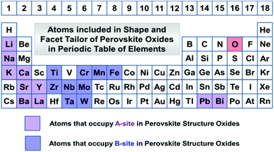 | ||
| Fig. 1 Elements involved in perovskite structure oxides that can be tailored with the crystal shapes and facets in this review. | ||
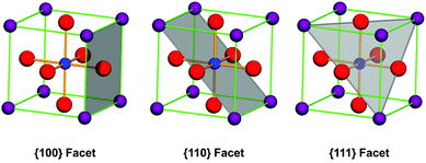
According to the crystal growth principles, facets with the lowest surface energy grow the most slowly. In crystal growth processes, surface atom coordination reduces surface energy by changing active kink atoms into bonded ones. Thus, crystal facets with the most bonded atoms are the most stable in the process of crystal growth. Let us take cubic structure perovskite oxides as an example. The most coordinated balance facets are {100} facets and the most common shape of these structure materials is cubes in the final shape of each single crystal. This is because on these crystal planes, facet atoms are the nearest neighbor connections between each other as A–O or B–O series with either A–O or B–O layer termination at the surface. The {111} facets are also possibly stable facets because the bond of either A- or B-site cations can be balanced by O-atoms at the corresponding crystallographic sites (Fig. 2). For {110} facets, they can only be stable by forming steps along these directions, because atoms at the surface are extremely unsaturated bonding in contrast with that in the crystal lattice. However, the BO6 octahedron in perovskite structure oxides may show some degree of distortion along some direction due to the size effect of A-site cations, which lowers the symmetry of the ideal perovskite to tetragonal, orthogonal, hexagonal and triclinic, and the unit cells have been redefined. But the most stable atomic structure at the surface will not change due to the charge balance principles. In this review, we define the crystal facets of perovskite oxides with respect to their corresponding primitive unit cells.
In this section, crystal facet and shape tailoring in various perovskite structure oxides will be discussed in detail. The facet tailoring should be based on the primitive crystal structure of each compound, i.e. the unit cell parameters. A detailed discussion of crystal facet tailoring of each family of perovskite structure oxides is as follows.
3.1 Tungsten and molybdenum trioxide
Tungsten and molybdenum trioxide are widely studied transition metal oxides owing to their excellent properties in catalysis, sensor,33 and electrochromic (EC) applications. WO3 crystals are generally grown by corner and edge sharing of WO6 octahedra (i.e. oxygen atoms). It will form different phases based on corner-shared WO6 octahedra, i.e. monoclinic II (ε-WO3), triclinic (δ-WO3), monoclinic I (γ-WO3), orthogonal (β-WO3), tetragonal (α-WO3), and cubic WO3. The phase discrimination is based on the tilting angle and rotation of WO6 octahedra with reference to the ideal cubic phase (ReO3 structure). Besides WO3, there are four kinds of hydrates, WO3·2H2O (dihydrate), WO3·H2O (monohydrate), WO3·0.5H2O (hemihydrate), and WO3·0.33H2O. Thus, the structural versatility enables a lot of shapes of the WO3 crystals,34 such as nanorods,35 nanowires,36 nanobelts,37 nanotubes,38 nanoplates,39 nanodiscs40 and nanocuboids.41 The surfactant was usually used to tailor the morphology and dimensions of the final shape of these nanostructures. Monoclinic WO3 could be prepared as nanoplates by hydrothermal treatment of Na2WO4·2H2O solutions with the assistance of 6 M HCl and NH4NO3. When polyethylene glycol (PEG) was added into this synthetic system, the nanoplates were changed into nanorods.42Liu et al. reported a facile route to prepare cube WO3 with nearly equal percentage of {002}, {200} and {020} facets and rectangular sheet-like WO3 crystals with predominant {002} facet by controlling acidic hydrolysis of tungsten boride.43 Due to the difference in crystal facet structure, these two kinds of WO3 show different activities in photocatalytic water oxidation and photoreduce CO2 to generate CH4, respectively.
The prototype of perovskite structure is derived from ReO3-type oxides, in which the building unit BO6 octahedron is connected to each other by corner-shared O ions. Thus, the crystal structure forms an A-site vacancy with BO6 forming a network. WO3 and MoO3 have similar structures as ReO3 with a small distortion from the {111} direction, which is because of the smaller size of W than Re and it may be easy to combine with H forming HxWO3.
Shape tailoring of single-crystalline tungsten oxide octahedra was first reported by Miyauchi et al.44 Based on the Karst formation mechanism, they developed an NH3 dependent facet protection route to prepare octahedron shaped WO3 sub-microcrystals by inhibition of corrosion by HCl and subsequent recrystallization at the surface. Although the bonding {111} planes are not the lowest energy surfaces, with the help of NH3, a thin tungstic acid layer is covered on this plane (Fig. 3(a)), which helps to stabilize the octahedron morphology (Fig. 3(b)). Usually, WO3 is orthorhombic in space groups, with a slightly longer a. Thus, the crystal shape of small single crystals of WO3 is mainly cubes. In the presence of NH4+ in synthesis solution, octahedron shaped sub-micrometer crystals were prepared. Although the formation mechanism of octahedral WO3 was not discussed in detail, NH4+ seemed to play an important role in crystal growth and shape tailoring processes. Li et al. prepared hexagonal WO3 single crystal nanorods grown along the [110] axis with the assistance of NH4+ under hydrothermal conditions.45 They concluded that NH4+ cations are strongly adsorbed on the active (001) facets, which play an important role in determining the crystal growth orientation along either the [110] or [001] axis. In the presence of ethylenediaminetetraacetic acid (EDTA), a uniform hexagonal WO3 nanowire could be synthesized.46 When NH4+ species were introduced into this reactive condition, urchin-like structure WO3 could be prepared. Although the formation mechanism of this urchin structure was not discussed, NH4+ seemed to play an important role in this nanostructure material growth.
 | ||
| Fig. 3 (a) XRD pattern and (b) typical SEM image of the as-prepared octahedral crystals. The asterisks represent diffractions corresponding to tungstic acid (H2W1.5O5.5·H2O).44 Reproduced with permission from The Royal Society of Chemistry. | ||
Yuan et al. adopt an RF induction thermal plasma method to prepare standard monoclinic γ-WO3.47 The surface energy associated with crystallographic planes in WO3 usually follows a general sequence: γ{111} < γ{100} < γ{110}.48 In their method, the ideal octahedron with exposed {111} planes was obtained.
Many efforts have been made at the synthesis and shape tailoring of WO3, but the shapes of WO3 were mainly shown as one-dimensional (rod, wire, tube) and two-dimensional (belt, plate, disk), as well as three-dimensional cuboids. This may be due to the crystal structure of WO3 being highly distorted with respect to cubic structure ReO3 type. Yuan and Ding et al. proposed a dopant-controlled strategy to synthesize and tailor the morphology of WO3 polyhedra by the RF thermal plasma method.49 In their results, WO3 products without dopants showed octahedral shape with {111} exposed facets, due to the high growth speed in the [100], [010] and [001] directions (Fig. 4(a)). If the concentration of Cr dopants is 2.5% atomic ratio, i.e. 2.5 at% Cr–WO3, the (001), (010), and (100) facets are exposed (Fig. 4(b)). With the increase of dopants of Cr species, i.e. 10.0 atom% Cr–WO3, the crystals formed regular cubes with (100), (010) and (001) exposed facets (Fig. 4(c)). The formation mechanism was interpreted as a Cr-effect on the crystal growth speed and surface energy changes under RF thermal plasma conditions.
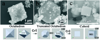 | ||
| Fig. 4 Synthesis of Cr-doped WO3 polyhedra controlled by tailoring the intrinsic thermodynamic properties in RF thermal plasma. (a) WO3, (b) 2.5 at% Cr–WO3 and (c) 10.0 at% Cr–WO3.49 Copyright 2015 American Chemical Society. | ||
For the shapes of MoO3, similar to WO3, the mainly morphology is one-dimensional nanowire, nanorod,50 nanofiber,51 nanobelt52 and nanotube.53 The length of the MoO3 nanowire could be controlled by simply changing the ionic environment, such as in acidic, water, or neutral ionic media. When poly(ethylene glycol) (PEG) was added to the synthesis system, the diameter of the nanowire reduced, and the final shape of MoO3 changed as whiskers.54 In contrast, if polyvinylpyrrolidone (PVP) molecules were added into the reactive solution, the shape of MoO3 changed into short microrods.55 Chitosan and cetyltrimethylammonium bromide (CTAB) could be effective shape directing agents, which may tailor the shape of MoO3 as particle-assembled flowers and microbelt, respectively.56 Lee et al. added thiourea as a capping agent in MoO3 synthesis, and a pyramidal and prismatic hexagonal shape product was formed.57 This result indicates that NH4+ plays an effective role in shape directing of MoO3 synthesis.
In summary, although many methods have been reported on the preparation of various WO3 nanostructures, the synthesis conditions with regard to a shape tailoring art are less discussed. Even for the simplest perovskite-like compound, the facet and shape tailoring is quite limited. Only several papers have been concerned with the crystal facet tailoring growth and the corresponding facet-dependent chemical activities. The reported exposed crystal facets are in accordance with the expected facets indicated in section 2. Shape tailoring in MoO3 is very difficult, and the single crystal of MoO3 is mainly one-dimensional in the final shape. The polymer and the surfactant under the synthesis conditions seemed to play an important role in the shape directing process. The existence of NH4+ is shown as an effective capping agent in some crystal facets and to discuss the detailed mechanism, a further understanding of the high index crystal facet formation is needed.
3.2 Niobate and tantalite
Perovskite niobate and tantalite oxides are famous functional materials in energy conversion, intelligent sensors, piezoelectric actuators, and holographic data storage, due to their nonlinear optical,58 ferroelectric,59 piezoelectric,60 and superior photocatalytic61 behaviours.Zhu et al. prepared series of sodium niobate with controllable shapes by a hydrothermal method.62 Hydrothermally grown sodium niobate usually gives a variety of products, such as Na8Nb6O19·nH2O, Na2Nb2O6·nH2O, as well as hexagonal NaNbO3. In their method, the mineralizer for synthesizing perovskite structure NaNbO3 crystals should be a mixed KOH and NaOH solution. The shape could be tailored by tuning the concentration of the mixed KOH and NaOH, but the shape and as-grown crystal facets are not as uniform as in samples prepared in the presence of a surfactant.
Xue et al. proposed an ion exchange method in solution phase to crystallize NaNbO3 cubic microcrystals adapted from potassium niobate hollow sphere precursors.63 With the assistance of polyacrylamide (PA), a gradual shape evolution of NaNbO3 microcrystals from octahedra to cubes could be realized (Fig. 5(c)). The water-soluble long-chain PA molecules promote the transport of Nb–O species toward the growth interface due to the interactions of functional groups on PA with alkaline solutions. It seems that {111} facets are prone to be preserved in the presence of PA (Fig. 5(a)), and the final shape of NaNbO3 is mainly octahedral with the hydrothermal treatment time of 48 h. On increasing the synthesis time to 72 h, {100} facets grow more quickly (Fig. 5(b)), and truncated octahedral geometries as well as cubes were formed under this condition. The prolonged reaction time makes it easy to grow {100} facets, which may also indicate that it is more active in {111} facets than that of {100}. If the amount of NaOH doubled, uniform truncated orthorhombic NaNbO3 octahedra (Fig. 5(d)) and NaNbO3 cubes (Fig. 5(e)) were prepared in 48 and 72 h, respectively. Besides, ethylene glycol (EG) and ethylenediamine (EN) may also work as a morphology tailoring agent according to their research.
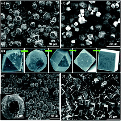 | ||
| Fig. 5 SEM images of the as-prepared NaNbO3 products in the presence of PA additive. (a) NaOH 1.0 g, PA 0.20 g, 48 h; (b) NaOH 1.0 g, PA 0.20 g, 72 h; (c) shape evolution of NaNbO3 crystals from octahedra to cubes, (d) NaOH 2.0 g, PA 0.10 g, 48 h; (e) NaOH 2.0 g, PA 0.10 g, 72 h.63 Reproduced with permission from The Royal Society of Chemistry. | ||
Zhang et al. grew different crystal planes of NaNbO3 single crystal films by the pulsed laser deposition (PLD) technique, which show anisotropy photocatalytic oxidization activity on RhB degradation and the catalysis degrees followed the sequence (100) < (110) < (111).64 They believe that this activity is in accordance with the activity of OH− generation on each crystal facet of grown films.
Magrez et al. developed a ternary phase diagram of KOH–Nb2O5–H2O for synthesizing KNbO3 in a hydrothermal environment, which shows that the crystal shape of the KNbO3 single crystal nanostructure could be tailored accordingly.65 Single-crystalline KNbO3 nanocubes with the size of 300 nm could be synthesized in KCl by rapid sintering and quenching to room temperature in air.66 The products are crystallized as orthorhombic space group Cm2m. With the assistance of the sodium dodecyl sulphate (SDS) surfactant, the shape of KNbO3 could be evolved from cubes to nanorods in hydrothermal processes.67 The concentration of SDS is essential for the shape formation of KNbO3, which may be interpreted in a surfactant-mediated self-assembly oriented aggregation mechanism.
Chen et al. reported that polyhedral NaNbO3 could be prepared with the exposed facets of {110} by simply treating Nb2O5 and NaOH in a hydrothermal environment without adding any surfactant.68 However, the detailed experimental processes had not been given and for NaTaO3 and KNbO3, no similar results were known.
Mixed niobate (K1−xNax)NbO3 elongated cubes and nanorods could also be prepared by the hydrothermal method.69 With low amounts of Na at the A-site, the niobates retain an orthorhombic structure, while it changes into monoclinic if the dominant element at the A-site is Na.70 Zhu et al. found that the ratio of K+/(K+ + Na+) and the concentration of all alkalines in the starting solution make the cubes grow more steps at the surface.71 Vertically aligned (K,Na)NbO3 nanorod arrays in the (100) direction could also be grown by the hydrothermal method on substrates, which can be fabricated as a device for piezoelectric power generation.72 Wang et al. synthesized octahedra and nanosheets of tantalate K1.9Na0.1Ta2O6·2H2O and the {111}-facet-bound nanooctahedra show more than 3 times higher photocatalytic water splitting activity than the nanosheets dominated by {101} facets.73
Nearly cubic shaped AgNbO3 micrometer sized crystals could be prepared by hydrothermal treatment of NH4HF2, Ag2O, and Nb2O5 raw chemicals.74 The most stable phase of AgNbO3 at room temperature is orthorhombic with the space group Pmc21. The symmetry will improve with increasing temperature, and it will change into tetragonal at 723 K and cubic at 873 K. The primitive unit cell parameters of a, b, and c are similar at room temperature (300 K), which makes cubic the final shape of AgNbO3. In the presence of ethylene glycol (EG), AgNbO3 could also form step- or rhomb-shaped polyhedra, but the crystal formation mechanism has not been discussed.75
Crystals of NaTaO3 were usually grown with cubic morphology under hydrothermal conditions, which indicates that the growth speed in the six {100} planes are the lowest.76 With the assistance of microwaves, NaTaO3 nanocubes could be prepared and showed excellent photocatalytic activity for overall water splitting compared to conventional hydrothermally prepared samples.77 Kuang and Xie et al., however, tailored NaTaO3 single crystals from cubes to quasi-spheres by merely changing the volume ratio of ethylene glycol (EG) to water and the amount of NaOH under the synthetic conditions (Fig. 6).78 It seems that EG plays an essential role in the shape evolution of NaTaO3 by tailoring the growth speed in the {110} and {111} planes due to the capping effect of polar groups. For hydrothermally prepared LiTaO3 crystals, however, the microcube shapes are highly distorted with the crystal space group R3c, because the smallest metal cation size of the Li-cation changed the unit cell into a hexagonal crystal system.79 For much larger sized Ag+ at the A-site of AgTaO3, the shape of crystals is also cubic-like due to the orthorhombic system (space group Pcmn) for the as-prepared crystals.80 Wang et al. reported a method to controllably synthesize mixed K, Na doped crystals of K1.9Na0.1Ta2O6·2H2O (KNTO) with octahedra (enclosed by {111} facets) and nanosheets (dominated by {101} facets) shapes, and the octahedra exhibit more than 3 times higher activity in photocatalytic H2 evolution from CH3OH/H2O solution than that of nanosheet samples.81 Gu et al. used different additives of polyethylene glycol (PEG) to prepare KTa1−xNbxO3via the hydrothermal method at 200 °C.82 KTaO3 nano-octahedra could be prepared with mainly exposed facets of {111} because they are crystalized into the Pm![[3 with combining macron]](https://www.rsc.org/images/entities/char_0033_0304.gif) m space group (Fig. 7).
m space group (Fig. 7).
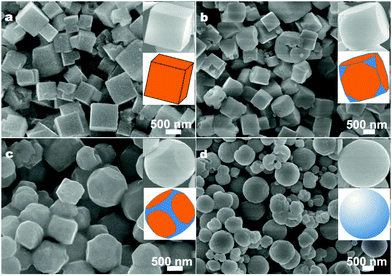 | ||
| Fig. 6 SEM images of NaTaO3 crystals obtained with 10 mmol NaOH and different volume ratios of EG to water: (a) 1/13, (b) 3/11, (c) 5/9, and (d) 11/3. Insets are the corresponding SEM images and schematic models.78 Copyright Springer and Science China Press. | ||
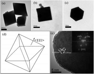 | ||
| Fig. 7 TEM images of KTaO3 octahedra: (a–c) with electron beams parallel to <110>, <100>, and <111>, respectively, (d) the scheme of octahedra; (e) the HRTEM image of KTaO3 octahedra with an electron beam parallel to the <111> direction; the inset shows the two dimensional Fourier transform patterns of the corresponding HRTEM image.82 Copyright 2008 American Chemical Society. | ||
3.3 Titanate and zirconate
Usually, hydrothermally prepared SrTiO3 crystals are cubes, BaTiO3 dodecahedral, and CaTiO3 rectangular prisms.83 CaTiO3, which is the mother mineral for the perovskite prototype, has received a lot of attention due to its dielectric, catalytic and bio-compatibility properties and implant bone applications.84 Usually, CaTiO3 single crystals are prepared by effectively treating the mixture of calcium nitrate and tetrabutyl titanate [Ti(OC4H9)4, TNB]. Similar to niobate and tantalite, crystal facets of CaTiO3 could also be tailored in PEG [poly(ethylene glycol)] solutions due to the same facet-directing effect. Duan et al., by varying the water or water-free system, prepared different shapes (octahedral, cube, rectangular bar) of CaTiO3 crystals with the assistance of PEG via the solvo/hydrothermal method.85 Dong et al. reported the synthesis of well-defined perovskite MTiO3 (M = Ba, Sr, Ca, and Mg) nanostructures by the hydrothermal method. By increasing the hydrothermal treatment period, CaTiO3 crystals transform from nanowires into hollow rectangular bars.86 The hollow crystal growth mechanism has been discussed as a surface-adsorbed polymer on the {100}c surfaces of the nanocubes.87 Yu et al. changed the pure water solution into an ethanol and water mixed-solution, and tubular and non-tubular rectangular prisms could be prepared.88 The prism is defined by the (111) and (202) planes growing in the [121] direction.89 Platelet-like perovskite CaTiO3 samples have only been reported by thermal transformation of Kassite CaTi2O5(OH2).90 Kimijima and Kanie et al. prepared rod-like, cubic, and concave-cubic CaTiO3 crystals with titanium(IV) tetraisopropoxide as a Ti-source and triethanolamine as a shape directing agent, and concave samples show high activity toward both H2 evolution and CO2 evolution.91Strontium titanate (SrTiO3) is an ideal substrate material for epitaxial growth of many functional materials with its own high dielectric constant, thermal stability, and photocatalytic properties. Precisely controllable synthesis of microscale or even nanoscale morphological and structural crystalline particles and thin films is less than satisfactory. 3D SrTiO3 microscale superstructures have been prepared via the hydrothermal method by self-assembly (SA) behaviour.92 Buscaglia et al. reported size and shape control of SrTiO3 particles grown by the epitaxial self-assembly method by adding organic molecules, in which the size of SrTiO3 was well-controlled,93 to the shape or crystal facets; however, it is still not as good as that of noble metal nanocrystals.
SrTiO3 nanocubes with an average length of ca. 20 nm could be prepared via the solvothermal method in mixed ethanol and 2-methoxy ethanol solutions.94 Toshima et al. reported multi-pod-like SrTiO3 crystals, as well as cubic and octahedral samples by the self-propagating high-temperature synthesis (SHS) method; however, the detailed crystal formation mechanism was not discussed clearly.95 Souza et al. found that the particle size and morphology of SrTiO3 could affect the photoluminescence properties and in their result, dodecahedron shaped SrTiO3 evolved in hydrothermally 40 min treated samples, but the shape formation mechanism of this sample was not discussed clearly.96 If the SrTiO3 synthesis solvent is monoethanolamine, single-crystal SrTiO3 dense spheres could be prepared.97 When diethanolamine and triethanolamine were used to substitute monoethanolamine, the average diameter of the SrTiO3 could be reduced greatly. This means that larger size of capping ligand molecules could tailor the shape of crystals effectively.
Weng and Han synthesized a series of SrTiO3 polyhedral submicro/nanocrystals with the shape evolution from cubic to edge-truncated cubic and truncated rhombic dodecahedra by fine tuning the starting chemical concentration and pKa value of the alcohols (Fig. 8).98
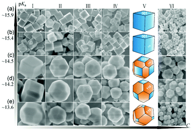 | ||
| Fig. 8 Shape evolution of SrTiO3 at different pKa values and concentrations.98 High pKa values lead to the exposure of more {001} facets, while low pKa values lead to {110} facets in SrTiO3 crystal growth processes.98 Copyright Springer and Tsinghua University Press. | ||
BaTiO3 crystals synthesized by using molten mixed alkalis (NaOH and KOH) were cubes with size from 70 to 100 nm at different reaction temperatures (165–220 °C).99 Wu and Zhou et al. prepared dodecahedral BaTiO3 with the assistance of polyethylene glycol-200 (PEG-200) via a hydrothermal reaction at 180 °C. This is due to the selective adsorption of PEG molecules on the {110} crystal planes of BaTiO3, which significantly reduced the crystal growth rate on these surfaces.100 BaTiO3 superstructured cage-like mesocrystals could be prepared via a molten hydrated salt reaction medium. The highly alkaline reaction environment of molten Ba(OH)2·8H2O facilitates the transformation of the TiO2 precursor to BaTiO3 through a dissolution–precipitation mechanism by forming [Ti(OH)x]4−x soluble titanium species.101 With the assistance of oleic acid (OLA) and butylamine under hydrothermal conditions, BaTiO3 nanocubes can be tailored into a hexapod morphology along the [001] direction.102
Beside titanates, zirconates could also be tailored into high-index facets. Wong et al. prepared BaZrO3 cubes and spheres by simply varying the cooling rates of the synthesis system by the NaOH–KOH mixture molten salt method.103 Li et al. developed a solvent dependent hydrothermal method by varying the ratio of water to ethanol to control the crystal growth of BaZrO3.104 In their results, a regular rhombic dodecahedron (enclosed by 12 {110} facets), a truncated dodecahedron (enclosed by {110} and {111} facets) and sphere shape BaZrO3 can be prepared by increasing the percentage of ethanol (Fig. 9), and the tailoring effect was attributed to the low polarity of solvents when ethanol was added to the reactants. Microwave treatment can also affect the growing speed in each direction of BaZrO3 single crystals under hydrothermal conditions.105 With the increase of the microwave periods, BaZrO3 agglomerates from the starting primary particles due to van der Waals forces, and evolves from a nearly spherical shape into a decaoctahedron (Fig. 10). In contrast, for SrZrO3 single crystal synthesis, only cubic samples were prepared in mixed NaOH and KOH solutions via the hydrothermal method.106
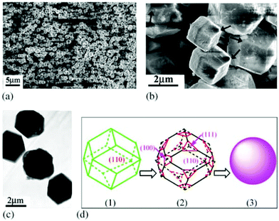 | ||
| Fig. 9 (a) Low- and (b) high-magnification SEM images of slightly truncated rhombic dodecahedral BaZrO3 microcrystals. The arrow shown in (b) is an indication of truncated corners. (c) A TEM image of the same batch of BaZrO3 microcrystals. (d) Simulated morphology evolution processes of the three states of regular rhombic dodecahedra, truncated dodecahedra and spheres.104 Copyright 2004 Elsevier. | ||
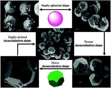 | ||
| Fig. 10 Powders obtained for (a) 10 and (b) 20 min and decaoctahedral BaZrO3 FE-SEM image of nearly spherical BaZrO3 powders obtained for (c) 40, (d) 80, and (e) 160 min.105a Copyright 2009 American Chemical Society. | ||
Although many methods have been used to develop high-index crystal facets of perovskite structure oxides, the single crystal size is usually very large compared with that of noble metal nanocrystal materials. Efforts have been invested in reducing the particle size of the structure of the materials. However, most of the previously reported papers showed no defined shapes for all of the as-prepared samples, as reported for BaTiO3, SrTiO3 and BaxSr1−xTiO3.107 In KOH/NaOH mixed solutions, cubic shaped BaTiO3 nanocrystals prepared via the hydrothermal method have the average particle size ranging from 70 to 100 nm.108 Solution-based growth of monodisperse cube-like BaTiO3 nanocrystals with a well-defined shape, a controllable size and a high degree of compositional homogeneity was carried out by thermal decomposition of metal fatty salts under hydrothermal conditions and the average length edge of each cubic nanocrystal was 22 nm.109 Dang et al. used bis(ammonium lactate) titanium dihydroxide (TALH) as Ti source, oleic acid and tert-butylamine as tailored surfactant to prepare BaTiO3 nanocrystals, and well-defined nanocubes with the size ranging from 20 to 50 nm were synthesized in a sealed autoclave when it was heated at 200 °C for 72 h.110 Similar results have been reported in Ma and Kato's work, with the particle size of BaTiO3 ranging from 15 to 30 nm (Fig. 11).111 Zhou et al., using ethanol as the solvent and oleic acid as the surfactant, prepared BaTiO3 nanocrystals with particle size as small as sub-10 nm.112 This phenomenon indicates that the polarity of the solvent also plays an important role in crystal size control. Xing and Kang et al. used a similar method to prepare BaTiO3 nanoparticles with various sizes ranging from 6 to 210 nm, and found that the coefficients of thermal expansion show a dependence on the size of different nanocrystals.113 Nanoscale small crystals of SrTiO3 (ca. 20 nm) can also be prepared under similar conditions with oleic acid and hydrazine as size controller agents.114 Wang et al. used triethylene glycol (TEG) to control the hydrolysis rate of tetrabutyl titanate in a NH4OH (25–28%) and PVP (K30) solution, and prepared sub-10 nm SrTiO3 nanocubes,115 which indicates that controlling the hydrolysis of organic metal precursor groups can also be used as an effective route to prepare small perovskite oxide nanocrystals. Hu, Marks and Poeppelmeier et al. varied the composition at the A-site of BaxSr1−xTiO3 nanocrystals in the presence of oleic acid and found that these cubic crystals could be assembled into two-dimensional arrays with the interparticle distance of 2.4 nm.116 The small sized perovskite nanoscale single crystals may be potentially used as the smallest photocatalysts and ferroelectric devices in the future.
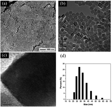 | ||
Fig. 11 (a) SEM, (b) TEM, (c) high-resolution TEM images and (d) DLS results of BaTiO3 nanocubes synthesized at 220 °C with a molar ratio of Ba![[thin space (1/6-em)]](https://www.rsc.org/images/entities/char_2009.gif) : :![[thin space (1/6-em)]](https://www.rsc.org/images/entities/char_2009.gif) OLA OLA![[thin space (1/6-em)]](https://www.rsc.org/images/entities/char_2009.gif) : :![[thin space (1/6-em)]](https://www.rsc.org/images/entities/char_2009.gif) butylamine = 1 butylamine = 1![[thin space (1/6-em)]](https://www.rsc.org/images/entities/char_2009.gif) : :![[thin space (1/6-em)]](https://www.rsc.org/images/entities/char_2009.gif) 18 18![[thin space (1/6-em)]](https://www.rsc.org/images/entities/char_2009.gif) : :![[thin space (1/6-em)]](https://www.rsc.org/images/entities/char_2009.gif) 18 for 72 h.111 Reproduced with permission from The Royal Society of Chemistry. 18 for 72 h.111 Reproduced with permission from The Royal Society of Chemistry. | ||
3.4 Ferrites, chromites and manganites
Perovskite structure ferrite, chromite and manganite oxides are also very important functional materials in many technological fields. Crystal facet tailoring in these families of materials is much less reported than that of other A+1B+5O3, A+2B+4O3 perovskites, which may be due to the more intense interaction of oxygen with A-site metal cations (A3+) than that corresponding A+1B+5O3 and A+2B+4O3 compounds.Du et al. reported the synthesis of single-crystalline BiFeO3 nanowires via the hydrothermal method with treated hydroxide precursors in 5 M NaOH solutions.117 Xu and Han et al. used ammonium bismuth citrate (C6H10BiNO8) as the starting chemical in the hydrothermal synthesis of BiFeO3, and single-crystalline microplates with dominant (012) facets were prepared.118 Polyethylene glycol (PEG, Mw = 4000) had also been shown as an effective crystal facet tailoring agent in preparing hydrothermally prepared BiFeO3 single crystals (Fig. 12).119 With different concentrations of KOH under reactive conditions, pill, rod and cubic shaped BiFeO3 samples could be obtained. With the assistance of PEG, at low KOH concentration (1 M), the main exposed facets of BiFeO3 (pills) are {111} (over 60% at the surface). When more KOH (2 M) was added to the reactive conditions, the growth speed of these facets was improved greatly, which makes the percentage drop to 20% in rod-shape BiFeO3 crystals. The cubic crystals could be prepared at a KOH concentration of 15 M with 100% exposed {100} facets. These results indicate that KOH concentration plays an important role when the crystal facet tailoring agent presents under reactive conditions in liquid phase crystal growth processes. Under molten salt conditions, the shape and structure evolutions of Bi1−xLaxFeO3 are more dependent on the A-site compositions than the synthesis conditions.120
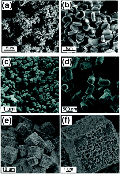 | ||
| Fig. 12 Low and high magnification images of BiFeO3 with different shapes: (a and b) pills, (c and d) rods, and (e and f) cubes.119 Copyright 2011 American Chemical Society. | ||
The synthesis of LaFeO3 is usually based on the high-temperature (more than several hundreds of °C) calcination of mixed La- and Fe-precursors,121 which results in polycrystalline products with no definite shape and exposed crystal facets. Although the floating zone method could be used to prepare large single crystals, it usually needs a long period and the as-prepared single crystals usually need further polishing and cutting to obtain the needed shapes and facets. Micro-sized single crystals of LaFeO3 could be prepared via molten NaOH flux122 or the hydrothermal route;123 however, only cubic crystals could be prepared under these conditions with the mainly exposed crystal facets {100}. In fact, perovskite structures of LnFeO3 compounds are usually crystalized into the orthorhombic phase with different lengths of the a, b, and c axes, which means different crystal growth speeds in the a, b, and c axes. Xing et al. reported the crystallization process of orthorhombic NdFeO3 in a hydrothermal environment with different concentrations of KOH, in which cuboid, cross-shaped and bar-shaped single crystals were prepared.124 This means the concentration of KOH plays an important role in the growth speed of NdFeO3 in the [100], [010] and [001] directions. Truncated octahedron shaped RERhO3 (RE = La, Pr, Nd, Sm, Eu, Tb) orthorhodites have also been reported via a K2CO3 flux method, but the shape formation mechanism has not been discussed.125
Urea may decompose into NH4+ and CO32− when reacted with H2O at temperatures above 160 °C. The resulting NH4+ was confirmed to be an effective modulator for perovskite structure oxides’ crystal facets. Recently, Feng et al. found an interesting phenomenon that NH4+ cations show effective capping function toward LaFeO3 single crystal growth in hydrothermal methods.126 In this method, urea was selected as the starting NH4+ source by decomposition at elevated temperature during a hydrothermal treated process. Concerning the concentration of urea, KOH, reaction temperature and period, each of these factors plays an important role in LaFeO3 crystal facet tailoring processes. For example, when 1.4 g urea was added to their reaction system, the largest area {110} facets of LaFeO3 were synthesized. Larger and smaller amounts of urea may reduce these high index facets (Fig. 13). They also verified the facet tailoring effect by adding iso-mole concentrations of (NH4)2CO3 to the reactive system, but it is not as good as that of urea. This is because the reactive conditions are based on a strong alkaline with a high concentration of KOH, and when (NH4)2CO3 is added, NH3 will release from the solution-deposition reactive mixtures based on the following equation (eqn (1)):
| NH4+ + OH− → H2O + NH3↑ | (1) |
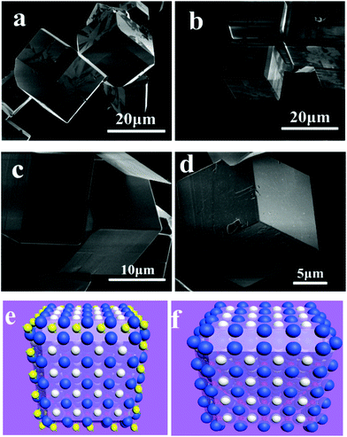 | ||
| Fig. 13 Chamfer box shape LaFeO3 crystals grown in a 240 °C hydrothermal environment with 5 g KOH and different amounts of urea: (a) 1.4 g; (b) 1.6 g; (c) 1.8 g and (d) 2.0 g. Schematics of (e) NH4+ attached onto the {110} facets and (f) the final shape of LaFeO3 crystals.126 Reproduced with permission from The Royal Society of Chemistry. | ||
Chamfer box shaped LaFeO3 crystals with exposed {110} and {111} facets were prepared in their paper, and the percentage of {110} facets could be tailored by varying the starting concentration of urea. They proposed that the NH4+ cation has a similar size to that of La3+ and it is a non-spherical cation that may sit on the A-site of LaFeO3 during the crystal growth process temporarily (Fig. 13(e and f)). This may repel other La3+ continuously attached on the neighbor A-site, thus making the corresponding facet growth more slowly than other un-capped facets. Finally, chamfer box shaped LaFeO3 with {110} facet single crystals could be prepared.
Perovskite structure chromites were usually prepared by traditional ceramic methods as well as other precursor-calcination processes.127 Similar to the afore-mentioned other perovskite structure oxides, chromites prepared by these methods are also polycrystalline with no well-defined shapes. High-128 and mild-hydrothermal129 methods have also been used to prepare chromites and the as-prepared samples of LaCrO3 are also cubic. NH4+ can also work as an effective facet-directing agent in hydrothermally growing LaCrO3 crystal processes.126 As shown in Fig. 14, with low amounts of urea (1.0 g), the shape of LaCrO3 remains cubic. When more urea was added to the reactive system, the shape of LaCrO3 becomes sphere-like due to the selective capping effect of NH4+ towards {110} and {111} facets in regard to the unit cell of LaCrO3.
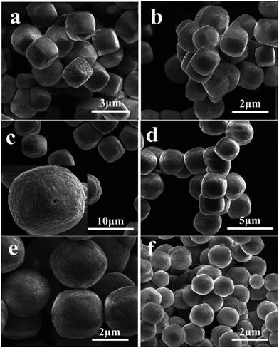 | ||
| Fig. 14 Shape evolution of LaCrO3 with different urea contents: (a) 1.0 g; (b) 1.2 g; (c) 1.4 g; (d) 1.6 g; (e) 1.8 g and (f) 2.0 g.126 Reproduced with permission from The Royal Society of Chemistry. | ||
Perovskite structure manganites La1−xMxMnO3 (M = Ca, Sr, Ba) usually crystallized into cubes with the exposed termination facets of {100} with respect to the primitive unit cell.130 Lu and Meng et al. reported that La0.5Ba0.5MnO3 single crystal flowers and cubes could be tailored by varying the concentration of KOH or filling fraction in the hydrothermal method.131 Similarly, La1−xSrxMnO3 can also form tree-like dendrites in hydrothermal treatment with heated temperature ranging from 220 to 300 °C for different times ranging from 2 h to 3 days.132 By changing the alkalinities under La0.7Sr0.3MnO3 preparative conditions, a cubic phase with low-dimensional structure and a monoclinic phase with a complex hollow structure could be prepared, which indicates that the KOH concentration plays an important role in crystal growth processes.133 Pure phase LaMnO3 micro-sized single crystals have only been reported in the molten salt method in NaCl–KCl and LiCl–KCl eutectic solvent mixtures, which is also cubic in shape with particle sizes lower than 2 μm.134 Single-crystal manganite nanowires of La0.5Ba0.5MnO3 and La0.5Sr0.5MnO3 have also been reported with typical widths of 30–150 nm and 50–400 nm, respectively.135 Park et al. reported the synthesis of La1−xBaxMnO3 single crystal nanocubes with adjustable doping levels via the hydrothermal method at 300 °C under autogenous pressure for 24 h.136 For other manganites, the crystal structures are much more divergent from cubic perovskite structure as in La1−xMxMnO3 (M = Ca, Sr, and Ba), and the crystal shapes are dependent on the size of A-site cations.137 In hydrothermally prepared La1−xSrxMnO3 single crystals, we found that the crystal shape could be tailored by adding some urea to the reactive solutions. NH4+ has also shown an effective tailoring effect towards La1−xSrxMnO3 under hydrothermal conditions.138 However, due to the complex interactions in La1−xSrxMnO3, such as charge ordering and mixed valance states, facet-growth and shape-tailoring in this family of compounds are much more difficult than that for LaFeO3 and LaCrO3. The crystal structure of La1−xSrxMnO3 changes with the La/Sr ratio, which makes the facet-directing processes different from each other in different ratios. When La/Sr = 0.5/0.5, i.e. La0.5Sr0.5MnO3, facet-tailoring shows changes along the {111} directions with respect to the primitive unit cell of perovskites (Fig. 15). The shape of La0.5Sr0.5MnO3 crystals grows from cuboctahedral (Fig. 15(a)) to truncated octahedral (Fig. 15(b)) to eventually octahedral (Fig. 15(c)). However, an inwardly directed dissolving effect may result in facet corruption along the {111} axis, which gradually changes the shape of the crystals (Fig. 15(d) and (e)) and finally produces a fractal pyramid shape (Fig. 15(f)). When La/Sr = 3/1, i.e. La0.75Sr0.25MnO3, the facet growth and the tailoring effect show changes along the {110} directions (Fig. 16). By introducing NH4+ into the reaction mixture for La0.75Sr0.25MnO3, the {100} facets grow coarsely, which may indicate that NH4+ has a destructive effect toward the face-shaping process (Fig. 16(a)). Along the {100} facets, the rough island grows longer and inwardly towards the face centre on each edge (Fig. 16(b)), and finally becomes a pyramid on each side of the {100} facets (Fig. 16(c) and (d)).
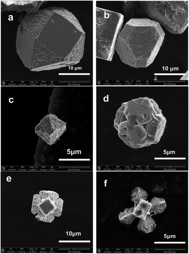 | ||
| Fig. 15 Hydrothermally prepared La0.5Sr0.5MnO3 single crystal evolution along the {111} direction: (a) truncated cubes; (b) truncated octahedra; (c) octahedra; (d) etched cubes along the {111} direction; (e and f) pyramids sharing one vertex.138 Reproduced with permission from The Royal Society of Chemistry. | ||
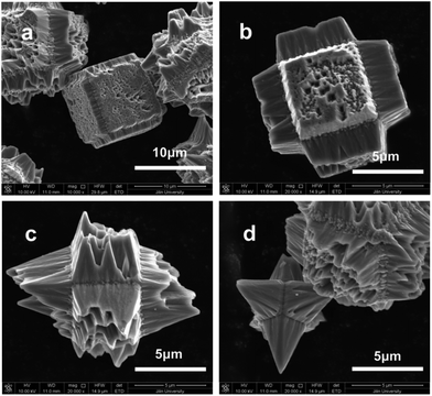 | ||
| Fig. 16 Crystal shape evolution along the {100} facets in La0.75Sr0.25MnO3.138 Reproduced with permission from The Royal Society of Chemistry. | ||
The crystal phase in La1−xSrxMnO3 is strongly related to the ratio of La/Sr at the A-site. La0.5Sr0.5MnO3 is pseudo-cubic, a = 3.849 Å. La0.75Sr0.25MnO3 crystals can be indexed into a slightly tilted (a = 5.471 Å, b = 7.768 Å, c = 5.529 Å; α = β = 90°, γ = 90.52°) monoclinic phase (space group: P21/a), which is closely related to orthorhombic phases with slightly tilted γ angles in the primitive cell, with ap = a/√2 = 3.869 Å, bp = b/2 = 3.884 Å, cp = c/√2 = 3.910 Å. Thus, the same effect induced by NH4+ occurs on each side of La0.5Sr0.5MnO3 in contrast to the asymmetrical effect on La0.75Sr0.25MnO3 crystals. These results indicate that the crystal facet tailoring should be based on the fundamental structure of crystals and the capping agent selection should be based on the structure of the building unit atomic groups.
4. Mechanism of perovskite structure oxide crystal facet tailoring
The basic principle of the crystal growth mechanism is generally discussed in many books. For facet and shape tailoring in many crystals, the basic thermodynamic and kinetic theories are the same. In perovskite structure compounds, it also follows this basic theory. However, how to use these theories to produce any shape and exposed facet of crystals we want is still a challenging aspect in the synthesis, preparation and fabrication of perovskite structure materials. The crystal facets are grown depending on the slowest growing speed in each possible direction of crystals.As can be seen in the above discussed sections, most of the stable facets in perovskite oxide are {100} facets with respect to the ideal cubic structure oxide. Long chain polar molecules, such as polyethylene glycol (PEG), can work as a surfactant in liquid method crystal growth processes by selectively capping the possible sites according to the unit cell for each family of crystals. The capping effect makes the crystal grow slowly in some directions due to the sites’ capping agent attachment.
In A+3B+3O3 perovskites, NH4+ has an important facet tailoring effect in these families of compounds. Usually, perovskite crystals formed from a solution medium (especially in hydrothermal routes with a high concentration of alkaline hydroxides) are terminated with an A–O layer, which leads to a positively charged surface because of the unsaturated bonds of the A-site cations. Some anions, such as OH− in alkaline solution, are prone to attach to the {100} facets of A-site cations to balance the charge discrepancy. Therefore, the final crystals are always terminated with {100} facets on their surfaces, and the crystals usually form cubic shapes. For the {111} facets, however, the terminal facets are one sided faces of the BO6 octahedra with negatively charged surfaces due to more amount of crystallographic oxygen on these facets. By introducing certain cations, such as NH4+, the B–O layer may be stabilized by charge compensation. The size of NH4+ is similar to that of A-site La3+ or some alkaline (e.g. K+) and alkaline earth cations (e.g. Sr2+). NH4+ is a tetrahedral structure with each N–H bond of the same length, which may have some weak interaction towards the face of BO6 octahedra. For example, in the preparation of La1−xSrxMnO3 crystals of different shapes in the presence of NH4+, La3+ (Sr2+) ions are enclosed by eight neighbour MnO6 octahedra to balance the negative charge of the BO6 groups, forming the unit cell structure of perovskite crystals. During the crystal growth process, K+ is weakly attached to the surfaces of the MnO6 octahedral during further growth along the perovskite unit cell, and is substituted by La3+ (Sr2+) after the growth of a further unit on the surface. NH4+, a cation with a non-spherical electric field, however, may attach to the MnO6 unit, forming the linkage N–H⋯O–Mn. Thus, when the crystals are grown by a normal hydrothermal method without NH4+, the crystals will grow into cubes because the slowest growing facets are {100} facets. If NH4+ cations were distributed into the reactive solutions, it will diminish the growing speed along the {111} facets due to the electrostatic or hydrogen bond interactions between NH4+ and BO6 octahedra, and the final shapes of crystals will be mainly exposed by their {111} facets with respect to their primitive unit cell, respectively (Fig. 17).
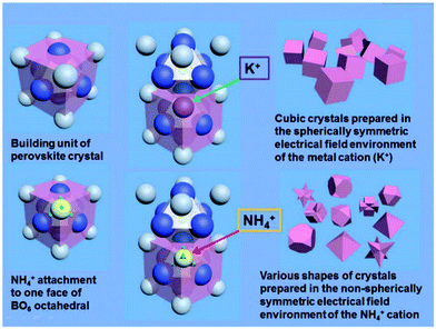 | ||
| Fig. 17 Evolution of perovskite crystal shapes in hydrothermal environments: according to the mechanism of crystallization of perovskites in a purely KOH environment, only cubic crystals can be prepared under these conditions; by the introduction of NH4+, various final crystal shapes emerge.138 Reproduced with permission from The Royal Society of Chemistry. | ||
5. Conclusion and outlook
Significant efforts have been devoted to perovskite structure oxides for single crystal particle size, shape, morphology as well as crystal facets over the past several years. Crystal facets of oxide materials can determine not only the intrinsic physical and chemical properties, but also provide new technological applications in catalysis, optics, electronics, and magnetics. In this review, we have summarized the recent progress of research in crystal facet tailor arts in perovskite structure oxides. Principles of perovskite structure oxides’ crystal growth as well as the experimental conditions were discussed in detail. Important materials of this structure were generally reviewed and the tailoring methods in the synthesis of different shape crystals were concluded. Representative compounds in each A/B valance state, i.e. A0B+6O3, A+1B+5O3, A+2B+4O3, and A+3B+3O3, as well as mixed valence state compounds and some solid solutions, were reviewed as far as our knowledge allowed. Crystal growth with tailored facets must follow the native crystal structure which plays the most important role in the crystal shapes and the possibility of each family of exposed facets. Capping effects of organic molecules and some small non-spherical symmetrical ions were discussed and summarized. The mechanism of perovskite structure oxide crystal facet tailoring was generally discussed finally. In conclusion, this is a new but more challenging aspect of perovskite structure oxide facet tailoring. As indicated by Duprez et al., although total replacement of noble metals by perovskite structure oxides is not possible in the near future,22 exposing crystal facets with different polarity and chemical activity is a suitable and possible route to improve the chemical performance of this family of materials while keeping the stability of these crystalline compounds. However, for most perovskite single crystalline materials, the particle sizes are usually larger than 1 micrometer, which endows these samples with a small specific surface area in comparison with that of nanocrystals. Thus, the synthesis of small perovskite particles with sizes below 200 nm is highly desirable and should be an important goal to achieve. At present, facet-dependent property investigations that can suffer using ultralarge sub-microcrystals and microcrystals are polarity dependent activities, such as spatial separation of photogenerated electrons and holes, facet dependent functional electronic components, gas sensors, as well as photocatalysts. Crystal facet tailoring in perovskite structure oxide materials may provide a new perspective and many new materials for further studying the surface electron states and other physical and chemical related applications in the near future.Acknowledgements
This work was supported by the National Natural Science Foundation of China (grants 90922034, 21131002, and 21201075) and the Specialized Research Fund for the Doctoral Program of Higher Education (SRFDP grant 20110061130005).Notes and references
- G. Dhanaraj, K. Byrappa, V. Prasad and M. Dudley, Springer Handbook of Crystal Growth, Springer-Verlag, Berlin, Heidelberg, 2010, ISBN: 978-3-540-74761-1 Search PubMed.
- Z. Quan, Y. Wang and J. Fang, Acc. Chem. Res., 2013, 46(2), 191–202 CrossRef CAS PubMed.
- Y. Li, Q. Liu and W. Shen, Dalton Trans., 2011, 40, 5811–5826 RSC.
- K. Zhou and Y. Li, Angew. Chem., Int. Ed., 2012, 51, 602–613 CrossRef CAS PubMed.
- C. Burda, X. Chen, R. Narayanan and M. A. El-Sayed, Chem. Rev., 2005, 105, 1025–1102 CrossRef CAS PubMed.
- (a) X. Peng, L. Manna, W. Yang, J. Wickham, E. Scher, A. Kadavanich and A. P. Alivisatos, Nature, 2000, 404, 59–61 CrossRef CAS PubMed; (b) C. Burda, X. Chen, R. Narayanan and M. A. El-sayed, Chem. Rev., 2005, 105(4), 1025–1102 CrossRef CAS PubMed.
- (a) X. Peng, Adv. Mater., 2003, 15, 459–463 CrossRef CAS PubMed; (b) M. A. El-Sayed, Acc. Chem. Res., 2004, 37, 326–333 CrossRef CAS PubMed; (c) S.-M. Lee, S.-N. Cho and J. Cheon, Adv. Mater., 2003, 15, 441–444 CrossRef CAS PubMed.
- C. Li, T. Bai, F. Li, L. Wang, X. Wu, L. Yuan, Z. Shi and S. Feng, CrystEngComm, 2013, 15, 597–603 RSC.
- Q. Kuang, X. Wang, Z. Jiang, Z. Xie and L. Zheng, Acc. Chem. Res., 2014, 47(2), 308–318 CrossRef CAS PubMed.
- G. Liu, H. G. Yang, J. Pan, Y. Q. Yang, G. Qing (Max) Lu and H.-M. Cheng, Chem. Rev., 2014, 114, 9559–9612 CrossRef CAS PubMed.
- S. Yang, B. X. Yang, L. Wu, Y. H. Li, P. Liu, H. Zhao, Y. Y. Yu, X. Q. Gong and H. G. Yang, Nat. Commun., 2014, 5, 5355 CrossRef CAS PubMed.
- (a) C.-H. Kuo and M. H. Huang, Nano Today, 2010, 5, 106–116 CrossRef CAS PubMed; (b) M. H. Huang, S. Rej and S.-C. Hsu, Chem. Commun., 2014, 50, 1634–1644 RSC.
- (a) C.-H. Kuo and M. H. Huang, J. Am. Chem. Soc., 2008, 130, 12815–12820 CrossRef CAS PubMed; (b) Y. Sui, W. Fu, Yi Zeng, H. Yang, Y. Zhang, H. Chen, Y. Li, M. Li and G. Zou, Angew. Chem., Int. Ed., 2010, 49, 4282–4285 CrossRef CAS PubMed; (c) Y.-H. Tsai, C.-Y. Chiu and M. H. Huang, J. Phys. Chem. C, 2013, 117, 24611–24617 CrossRef CAS.
- M. Leng, M. Liu, Y. Zhang, Z. Wang, C. Yu, X. Yang, H. Zhang and C. Wang, J. Am. Chem. Soc., 2010, 132, 17084–17087 CrossRef CAS PubMed.
- C.-S. Tan, S.-C. Hsu, W.-H. Ke, L.-J. Chen and M. H. Huang, Nano Lett., 2015, 15, 2155–2160 CrossRef CAS PubMed.
- D. Wang, H. Jiang, X. Zong, Q. Xu, Y. Ma, G. Li and C. Li, Chem. – Eur. J., 2011, 17(4), 1275–1282 CrossRef CAS PubMed.
- R. Li, F. Zhang, D. Wang, J. Yang, M. Li, J. Zhu, X. Zhou, H. Han and C. Li, Nat. Commun., 2013, 4, 1432 CrossRef PubMed.
- Y. Bi, S. Ouyang, N. Umezawa, J. Cao and J. Ye, J. Am. Chem. Soc., 2011, 133(17), 6490–6492 CrossRef CAS PubMed.
- B. Geng, C. Fang, F. Zhan and N. Yu, Small, 2008, 419(9), 1337–1343 CrossRef PubMed.
- R. J. H. Voorhoeve, D. W. Johnson Jr., J. P. Remeika and P. K. Gallagher, Science, 1977, 195, 827–833 CAS.
- J. Zhu, H. Li, L. Zhong, P. Xiao, X. Xu, X. Yang, Z. Zhao and J. Li, ACS Catal., 2014, 4, 2917–2940 CrossRef CAS.
- S. Royer, D. Duprez, F. Can, X. Courtois, C. Batiot-Dupeyrat, S. Laassiri and H. Alamdari, Chem. Rev., 2014, 114, 10292–11036 CrossRef CAS PubMed.
- (a) Y. Nishihata, J. Mizuki, T. Akao, H. Tanaka, M. Uenishi, M. Kimura, T. Okamoto and N. Hamada, Nature, 2002, 418, 164–167 CrossRef CAS PubMed; (b) A. Eyssler, A. Winkler, O. Safonova, M. Nachtegaal, S. K. Matam, P. Hug, A. Weidenkaff and D. Ferri, Chem. Mater., 2012, 24, 1864–1875 CrossRef CAS.
- (a) J. Suntivich, H. A. Gasteiger, N. Yabuuchi, H. Nakanishi, J. B. Goodenough and Y. Shao-Horn, Nat. Chem., 2011, 3, 546–550 CrossRef CAS PubMed; (b) J. Suntivich, K. J. May, H. A. Gasteiger, J. B. Goodenough and Y. Shao-Horn, Science, 2011, 334, 1383–1385 CrossRef CAS PubMed.
- (a) K. Huang, X. Chu, L. Yuan, W. Feng, X. Wu, X. Wang and S. Feng, Chem. Commun., 2014, 50, 9200–9203 RSC; (b) W. Si, Y. Wang, Y. Peng and J. Li, Angew. Chem., Int. Ed., 2015, 54(27), 7954–7957 CrossRef CAS PubMed.
- A. K. Opitz, A. Nenning, C. Rameshan, R. Rameshan, R. Blume, M. Hävecker, A. Knop-Gericke, G. Rupprechter, J. Fleig and B. Klözer, Angew. Chem., Int. Ed., 2015, 54, 2628–2632 CrossRef CAS PubMed.
- C. H. Kim, G. Qi, K. Dahlberg and W. Li, Science, 2010, 327, 1624–1627 CrossRef CAS PubMed.
- H. Zhan, X. Yang, C. Wang, C. Liang and M. Wu, J. Phys. Chem. C, 2010, 114(34), 14461–14466 CAS.
- S. G. Kwon and T. Hyeon, Acc. Chem. Res., 2008, 41(12), 1696–1709 CrossRef CAS PubMed.
- J. Zeng, Y. Zheng, M. Rycenga, J. Tao, Z.-Y. Li, Q. Zhang, Y. Zhu and Y. Xia, J. Am. Chem. Soc., 2010, 132(25), 8552–8553 CrossRef CAS PubMed.
- (a) S. Feng and R. Xu, Acc. Chem. Soc., 2001, 34(3), 239–247 CrossRef CAS PubMed; (b) D. R. Modeshia and R. I. Walton, Chem. Soc. Rev., 2010, 39, 4303–4325 RSC.
- Y.-W. Jun, J.-S. Choi and J. Cheon, Angew. Chem., Int. Ed., 2006, 45, 3414–3439 CrossRef CAS PubMed.
- H. Long, W. Zeng and H. Zhang, J. Mater. Sci.: Mater. Electron., 2015, 26, 4698–4707 CrossRef CAS.
- Z. Gu, T. Zhai, B. Gao, X. Sheng, Y. Wang, H. Fu, Y. Ma and J. Yao, J. Phys. Chem. B, 2006, 110, 23829–23836 CrossRef CAS PubMed.
- (a) J. Wang, E. Khoo, P. S. Lee and J. Ma, J. Phys. Chem. C, 2009, 113, 9655–9658 CrossRef CAS; (b) S. Bai, K. Zhang, R. Luo, D. Li, A. Chen and C. C. Liu, J. Mater. Chem., 2012, 22, 12643–12650 RSC; (c) J.-H. Ha, P. Muralidharan and D. K. Kim, J. Alloys Compd., 2009, 475, 446–451 CrossRef CAS PubMed.
- (a) A. Phuruangrat, D. J. Ham, S. J. Hong, S. Thongtem and J. S. Lee, J. Mater. Chem., 2010, 20, 1683–1690 RSC; (b) X. C. Song, Y. F. Zheng, E. Yang and Y. Wang, Mater. Lett., 2007, 61, 3904–3908 CrossRef CAS PubMed; (c) J. Zhang, J.-p. Tu, X.-h. Xia, X.-l. Wang and C.-d. Gu, J. Mater. Chem., 2011, 21, 5492–5498 RSC.
- X. Song, Y. Zhao and Y. Zheng, Mater. Lett., 2006, 60, 3405–3408 CrossRef CAS PubMed.
- J. Li, X. Liu, Q. Han, X. Yao and X. Wang, J. Mater. Chem. A, 2013, 1, 1246–1253 CAS.
- (a) D. J. Ham, A. Phuruangrat, S. Thongtem and J. S. Lee, Chem. Eng. J., 2010, 165, 365–369 CrossRef CAS PubMed; (b) J. Y. Zheng, G. Song, J. Hong, T. K. Van, A. U. Pawar, Do Y. Kim, C. W. Kim, Z. Haider and Y. S. Kang, Cryst. Growth Des., 2014, 14, 6057–6066 CrossRef CAS; (c) S. Lee, Y.-W. Lee, D.-H. Kwak, M.-C. Kim, J.-Y. Lee, D.-M. Kim and K.-W. Park, Ceram. Int., 2015, 41, 4989–4995 CrossRef CAS PubMed; (d) X. Su, F. Xiao, Y. Li, J. Jian, Q. Sun and J. Wang, Mater. Lett., 2010, 64, 1232–1234 CrossRef CAS PubMed; (e) T. Kida, A. Nishiyama, Z. Hua, K. Suematsu, M. Yuasa and K. Shimanoe, Langmuir, 2014, 30, 2571–2579 CrossRef CAS PubMed.
- L. Zhou, J. Zou, M. Yu, P. Lu, J. Wei, Y. Qian, Y. Wang and C. Yu, Cryst. Growth Des., 2008, 8, 3393–3398 Search PubMed.
- (a) S. Adhikari and D. Sarkar, RSC Adv., 2014, 4, 20145–20153 RSC; (b) S. Adhikari and D. Sarkar, J. Electrochem. Soc., 2015, 162(1), H58–H64 CrossRef CAS PubMed.
- D. J. Ham, A. Phuruangrat, S. Thongtem and J. S. Lee, Chem. Eng. J., 2010, 165, 365–369 CrossRef CAS PubMed.
- Y. P. Xie, G. Liu, L. Yin and H.-M. Cheng, J. Mater. Chem., 2012, 22, 6746–6751 RSC.
- Z.-G. Zhao, Z.-F. Liu and M. Miyauchi, Chem. Commun., 2010, 46, 3321–3323 RSC.
- J. Zhu, S. Wang, S. Xie and H. Li, Chem. Commun., 2011, 47, 4403–4405 RSC.
- J.-H. Ha, P. Muralidharan and D. K. Kim, J. Alloys Compd., 2009, 475, 446–451 CrossRef CAS PubMed.
- H. Zhang, M. Yao, L. Bai, W. Xiang, H. Jin, J. Li and F. Yuan, CrystEngComm, 2013, 15, 1432–1438 RSC.
- Z. L. Wang, J. Phys. Chem. B, 2000, 104, 1153–1175 CrossRef CAS.
- M. Yao, Q. Li, G. Hou, C. Lu, B. Cheng, K. Wu, G. Xu, F. Yuan, F. Ding and Y. Chen, ACS Appl. Mater. Interfaces, 2015, 7, 2856–2866 CAS.
- (a) X. W. Lou and H. C. Zeng, J. Am. Chem. Soc., 2003, 125, 2697–2704 CrossRef CAS PubMed; (b) A. Michailovski and G. R. Patzke, Chem. – Eur. J., 2006, 12, 9122–9134 CrossRef CAS PubMed; (c) Z. Cui, W. Yuan and C. M. Li, J. Mater. Chem. A, 2013, 1, 12926–12931 RSC; (d) J. Zhou, N. Lin, L. Wang, K. Zhang, Y. Zhu and Y. Qian, J. Mater. Chem. A, 2015, 3, 7463–7468 RSC.
- (a) G. R. Patzke Alexej Michailovski, F. Krumeich, R. Nesper, J.-D. Grunwaldt and A. Baiker, Chem. Mater., 2004, 16, 1126–1134 CrossRef; (b) K. Dewangan, N. N. Sinha, P. K. Sharma, A. C. Pandey, N. Munichandraiah and N. S. Gajbhiye, CrystEngComm, 2011, 13, 927–933 RSC.
- (a) T. Xia, Q. Li, X. Liu, J. Meng and X. Cao, J. Phys. Chem. B, 2006, 110, 2006–2012 CrossRef CAS PubMed; (b) L. Zhou, L. Yang, P. Yuan, J. Zou, Y. Wu and C. Yu, J. Phys. Chem. C, 2010, 114, 21868–21872 CrossRef CAS.
- S. Hu and X. Wang, J. Am. Chem. Soc., 2008, 130, 8126–8127 CrossRef CAS PubMed.
- C. V. Krishnan, J. Chen, C. Burger and B. Chu, J. Phys. Chem. B, 2006, 110, 20182–20188 CrossRef CAS PubMed.
- J. Guo, Y. Zhao, J. Zhao, J. Wu, Y. Song, Y. Tan, F. Wang, X. Hao, Y. Lu and F. Bao, Eur. J. Inorg. Chem., 2014, 3322–3329 CrossRef CAS PubMed.
- Z. Cui, W. Yuan and C. M. Li, J. Mater. Chem. A, 2013, 1, 12926–12931 CAS.
- V. Kumar, X. Wang and P. S. Lee, CrystEngComm, 2013, 15, 7663–7669 RSC.
- F. Dutto, C. Raillon, K. Schenk and A. Radenovic, Nano Lett., 2011, 11(6), 2517–2521 CrossRef CAS PubMed.
- C. Yan, L. Nikolova, A. Dadvand, C. Harnagea, A. Sarkissian, D. F. Perepichka, D. Xue and F. Rosei, Adv. Mater., 2010, 22(15), 1741–1745 CrossRef CAS PubMed.
- (a) J. H. Jung, M. Lee, J.-I Hong, Y. Ding, C.-Y. Chen, Li.-J. Chou and Z. L. Wang, ACS Nano, 2011, 5(12), 10041–10046 CrossRef CAS PubMed; (b) Y. Saito, H. Takao, T. Tani, T. Nonoyama, K. Takatori, T. Homma, T. Nagaya and M. Nakamura, Nature, 2004, 432, 84–87 CrossRef CAS PubMed.
- (a) Q.-P. Ding, Y.-P. Yuan, X. Xiong, R.-P. Li, H.-Bo Huang, Z.-S. Li, T. Yu, Z.-G. Zou and S.-G. Yang, J. Phys. Chem. C, 2008, 112, 18846–18848 CrossRef CAS; (b) K. Saito and A. Kudo, Inorg. Chem., 2010, 49, 2017–2019 CrossRef CAS PubMed; (c) S. F. Chen, L. Ji, W. M. Tang and X. L. Fu, Dalton Trans., 2013, 42, 10759–10768 RSC.
- K. Zhu, Y. Cao, X. Wang, L. Bai, J. Qiu and H. Ji, CrystEngComm, 2012, 14, 411–416 RSC.
- J. Wu and D. Xue, CrystEngComm, 2011, 13, 3773–3781 RSC.
- G. Li, G. Li, Y. Bai, W. Zhang and H. Zhang, Dalton Trans., 2012, 41, 10194–10198 RSC.
- A. Magrez, E. Vasco, J. W. Seo, C. Dieker, N. Setter and L. Forró, J. Phys. Chem. B, 2006, 110, 58–61 CrossRef CAS PubMed.
- H. Ge, Y. Hou, M. Zhu, H. Wang and H. Yan, Chem. Commun., 2008, 5137–5139 RSC.
- G. Wang, S. M. Selbach, Y. Yu, X. Zhang, T. Grande and M.-A. Einarsrud, CrystEngComm, 2009, 11, 1958–1963 RSC.
- J. W. Liu, G. Chen, Z. H. Li and Z. G. Zhang, Int. J. Hydrogen Energy, 2007, 32, 2269–2272 CrossRef CAS PubMed.
- C. Sun, X. Xing, J. Chen, J. Deng, Lu Li, R. Yu, L. Qiao and G. Liu, Eur. J. Inorg. Chem., 2007, 1884–1888 CrossRef CAS PubMed.
- A. D. Handoko and G. K. L. Goh, Green Chem., 2010, 12, 680–687 RSC.
- L. Bai, K. Zhu, L. Su, J. Qiu and H. Ji, Mater. Lett., 2010, 64, 77–79 CrossRef CAS PubMed.
- P. G. Kang, B. K. Yun, K. D. Sung, T. K. Lee, M. Lee, N. Lee, S. H. Oh, W. Jo, H. J. Seog, C. W. Ahn, I. W. Kim and J. H. Jung, RSC Adv., 2014, 4, 29799–29805 RSC.
- Y. Li, S. Chen, H. He, Y. Zhang and C. Wang, ACS Appl. Mater. Interfaces, 2013, 5, 10260–10265 CAS.
- H. Chang, M. Shang, M. Shang, H. Yuan and S. Feng, J. Am. Ceram. Soc., 2012, 95, 3673–3677 CrossRef CAS PubMed.
- W. Wang, G. Li, Y. Bai, N. Yang and W. Zhang, J. Phys. Chem. Solids, 2011, 72, 1451–1461 Search PubMed.
- (a) Y. He, Y. Zhu and N. Wu, J. Solid State Chem., 2004, 177, 3868–3872 CrossRef CAS PubMed; (b) X. Li and J. Zang, J. Phys. Chem. C, 2009, 113, 19411–19418 CrossRef CAS.
- J. Shi, G. Liu, N. Wang and C. Li, J. Mater. Chem., 2012, 22, 18808–18813 RSC.
- W. Chen, Q. Kuang and Z. Xie, Sci. China Mater., 2015, 58, 281–288 CrossRef.
- X. X. Gong, M. Fang, G. T. Fei, M. Liu, F. D. Li, G. L. Shang and L. D. Zhang, RSC Adv., 2015, 5, 31615–31621 RSC.
- L.-j. He, D. Zhang, S. Feng, B. Zou and G. Chen, Chem. Res. Chi. Univ., 2012, 28(5), 760–763 CAS.
- Y. Li, S. Chen, H. He, Y. Zhang and C. Wang, ACS Appl. Mater. Interfaces, 2013, 5, 10260–10265 CAS.
- Y. Hu, H. Gu, Z. Hu, W. Di, Y. Yuan, J. You, W. Cao, Y. Wang and H. L. W. Chan, Cryst. Growth Des., 2008, 882(3), 832–837 Search PubMed.
- J. Yang, B. Geng, Y. Ye and X. Yu, CrystEngComm, 2012, 14, 2959–2965 RSC.
- (a) C. Pecharromon, F. Esteban-Betegon, J. F. Bartolome, S. Lopez-Esteban and J. S. Moya, Adv. Mater., 2001, 13, 1541 CrossRef; (b) N. Ohtsu, K. Sato, A. Yanagawa, K. Saito, Y. Imai, T. Kohgo, A. Yokoyama, K. Asami and T. J. Hanawa, Biomed. Mater. Res., Part A, 2007, 82, 304 CrossRef PubMed.
- H. Zhao, Y. Duan and X. Sun, New J. Chem., 2013, 37, 986–991 RSC.
- W. Dong, B. Li, Y. Li, X. Wang, L. An, C. Li, B. Chen, G. Wang and Z. Shi, J. Phys. Chem. C, 2011, 115, 3918–3925 CAS.
- X. Yang, J. Fu, C. Jin, J. Chen, C. Liang, M. Wu and W. Zhou, J. Am. Chem. Soc., 2010, 132, 14279–14287 CrossRef CAS PubMed.
- D. Yu, J. Zhang, F. Wang, M. Zhao, K. Du, S. Shu, J. Zou and Y. Wang, Cryst. Growth Des., 2013, 13, 3138–3143 CAS.
- L. M. Lozano-Sánchez, S.-W. Lee, T. Sekino and V. Rodríguez-González, CrystEngComm, 2013, 15, 2359–2362 RSC.
- Y.-J. Huang, M.-C. Tsai, H.-T. Chiu, H.-S. Sheu and C.-Y. Lee, Cryst. Growth Des., 2010, 10, 1221–1225 CAS.
- T. Kimijima, K. Kanie, M. Nakaya and A. Muramatsu, CrystEngComm, 2014, 16, 5591–5597 RSC.
- X. Yuan, M. Zheng, Y. Zhang, T. Zhou, C. Li, X. Fang, L. Ma and W. Shen, Inorg. Chem., 2013, 52, 2581–2587 CrossRef CAS PubMed.
- V. R. Calderone, A. Testino, M. T. Buscaglia, M. Bassoli, C. Bottino, M. Viviani, V. Buscaglia and P. Nanni, Chem. Mater., 2006, 18, 1627–1633 CrossRef CAS.
- K. Nakashima, M. Kera, I. Fujii and S. Wada, Ceram. Int., 2013, 39, 3231–3234 CrossRef CAS PubMed.
- T. Toshima, H. Ishikawa, S. Tanda and T. Akiyama, Cryst. Growth Des., 2008, 895(7), 2066–2069 Search PubMed.
- A. E. Souza, G. T. A. Santos, B. C. Barra, W. D. Macedo Jr., S. R. Teixeira, C. M. Santos, A. M. O. R. Senos, L. Amaral and E. Longo, Cryst. Growth Des., 2012, 12, 5671–5679 CAS.
- G. Xu, Z. Tao, Y. Zhao, Y. Zhang, Z. Ren, G. Shen, G. Han and X. Wei, CrystEngComm, 2013, 15, 1439–1444 RSC.
- L. Dong, H. Shi, K. Cheng, Q. Wang, W. Weng and W. Han, Nano Res., 2014, 798(9), 1311–1318 CrossRef.
- J. Miao, C. Hu, H. Liu and Y. Xiong, Mater. Lett., 2008, 62, 235–238 CrossRef CAS PubMed.
- H. Zhan, X. Yang, C. Wang, J. Chen, Y. Wen, C. Liang, H. F. Greer, M. Wu and W. Zhou, Cryst. Growth Des., 2012, 12, 1247–1253 CAS.
- J. Li, S. Hietala and X. Tian, ACS Nano, 2015, 9, 496–502 CrossRef CAS PubMed.
- F. Dang, K. Mimura, K. Kato, H. Imai, S. Wada, H. Haneda and M. Kuwabara, Nanoscale, 2012, 4, 1344–1349 RSC.
- H. Zhou, Y. Mao and S. S. Wong, Chem. Mater., 2007, 19, 5238–5249 CrossRef CAS.
- Z. Lu, Y. Tang, L. Chen and Y. Li, J. Cryst. Growth, 2004, 266, 539–544 CrossRef CAS PubMed.
- (a) M. L. Moreira, J. Andrés, J. A. Varela and E. Longo, Cryst. Growth Des., 2009, 9, 833–839 CrossRef CAS; (b) L. R. Macario, M. L. Moreira, J. Andrés and E. Longo, CrystEngComm, 2010, 12, 3612–3619 RSC.
- K. Nakashima, I. Fujii and S. Wada, J. Cryst. Growth, 2013, 376, 35–40 CrossRef CAS PubMed.
- (a) M. Niederberger, G. Garnweitner, N. Pinna and M. Antonietti, J. Am. Chem. Soc., 2004, 126, 9120–9126 CrossRef CAS PubMed; (b) V. Bansal, P. Poddar, A. Ahmad and M. Sastry, J. Am. Chem. Soc., 2006, 128, 11985–11963 CrossRef PubMed; (c) M. B. Smith, K. Page, T. Siegrist, P. L. Redmond, E. C. Walter, R. Seshadri, L. E. Brus and M. L. Steigerwald, J. Am. Chem. Soc., 2008, 130, 6955–6963 CrossRef CAS PubMed; (d) C. W. Beier, M. A. Cuevas and R. L. Brutchey, J. Mater. Chem., 2010, 20, 5074–5079 RSC.
- J. Miao, C. Hu, H. Liu and Y. Xiong, Mater. Lett., 2008, 62, 235–238 CrossRef CAS PubMed.
- S. Adireddy, C. Lin, B. Cao, W. Zhou and G. Caruntu, Chem. Mater., 2010, 22, 1946–1948 CrossRef CAS.
- F. Dang, K. Mimura, K. Kato, H. Imai, S. Wada, H. Haneda and M. Kuwabara, Nanoscale, 2012, 4, 1344–1349 RSC.
- Q. Ma, K.-i. Mimura and K. Kato, CrystEngComm, 2014, 16, 8398–8405 RSC.
- J. Zhou and Z. Yang, CrystEngComm, 2013, 15, 8912–8914 RSC.
- M. Han, Y. Rong, Q. Li, X. Xing and L. Kang, CrystEngComm, 2015, 17, 1944–1951 RSC.
- F. Dang, K.-i. Mimura, K. Kato, H. Imai, S. Wada, H. Haneda and M. Kuwabara, CrystEngComm, 2011, 13, 3878–3883 RSC.
- Y. Hao, X. Wang and L. Li, Nanoscale, 2014, 6, 7940–7946 RSC.
- L. Hu, C. Wang, R. M. Kennedy, L. D. Marks and K. R. Poeppelmeier, Inorg. Chem., 2015, 54, 740–745 CrossRef CAS PubMed.
- B. Liu, B. Hu and Z. Du, Chem. Commun., 2011, 47, 8166–8168 RSC.
- X. Yang, G. Xu, Z. Ren, X. Wei, C. Chao, S. Gong, G. Shen and G. Han, CrystEngComm, 2014, 16, 4176–4182 RSC.
- L. Fei, J. Yuan, Y. Hu, C. Wu, J. Wang and Y. Wang, Cryst. Growth Des., 2011, 11(4), 1049–1053 CAS.
- J. Chen, R. Yu, L. Li, C. Sun, T. Zhang, H. Chen and X. Xing, Eur. J. Inorg. Chem., 2008, 3655–3660 CAS.
- (a) H. Xu, X. Hu and L. Zhang, Cryst. Growth Des., 2008, 8120(7), 2061–2065 CrossRef; (b) M. Sivakumar, A. Gedanken, W. Zhong, Y. H. Jiang, Y. W. Du, I. Brukental, D. Bhattacharya, Y. Yeshurun and I. Nowik, J. Mater. Chem., 2004, 14, 764–769 RSC; (c) F. Deganello, M. L. Tummino, C. Calabrese, M. L. Testa, P. Avetta, D. Fabbri, A. B. Prevot, E. Montoneri and G. Magnacca, New J. Chem., 2015, 39, 877–885 RSC.
- C. Shivakumara, Solid State Commun., 2006, 139, 165–169 CrossRef CAS PubMed.
- W. Zheng, R. Liu, D. Peng and G. Meng, Mater. Lett., 2000, 43, 19–22 CrossRef CAS.
- Y. Wang, X. Yan, J. Chen, J. Deng, R. Yu and X. Xing, CrystEngComm, 2014, 16, 858–862 RSC.
- R. B. Macquart, M. D. Smith and H.-C. zur Loye, Cryst. Growth Des., 2006, 6124(6), 1361–1365 Search PubMed.
- C. Hou, W. Feng, L. Yuan, K. Huang and S. Feng, CrystEngComm, 2014, 16, 2874–2877 RSC.
- (a) M. Iwasaki, H. Takizawa, K. Uheda, T. Endo and M. Shimada, J. Mater. Chem., 1998, 8, 2765–2768 RSC; (b) J. C. Rendón-Angeles, K. Yanagisawa, Z. Matamoros-Veloza, M. I. Pech-Canul, J. Mendez-Nonell and S. Diaz-de la Torre, J. Alloys Compd., 2010, 504, 251–256 CrossRef PubMed; (c) J. Prado-Gonjal, R. Schmidt, J.-J. Romero, D. Ávila, U. Amador and E. Morán, Inorg. Chem., 2013, 52, 313–320 CrossRef CAS PubMed; (d) K. Azegami, M. Yoshinaka, K. Hirota and O. Yamaguchi, Mater. Res. Bull., 1998, 33(2), 341–348 CrossRef CAS.
- K. Sardar, M. R. Lees, R. J. Kashtiban, J. Sloan and R. I. Walton, Chem. Mater., 2011, 23, 48–56 CrossRef CAS.
- (a) W. Zheng, W. Pang, G. Meng and D. Peng, J. Mater. Chem., 1999, 9, 2833–2836 RSC; (b) S. Wang, K. Huang, B. Zheng, J. Zhang and S. Feng, Mater. Lett., 2013, 101, 86–69 CrossRef CAS PubMed.
- (a) J. Spooren, R. I. Walton and F. Millange, J. Mater. Chem., 2005, 15, 1542–1551 RSC; (b) C. Li, T. Li, B. Wang and H. Yan, J. Cryst. Growth, 2006, 295, 137–140 CrossRef CAS PubMed; (c) S. Liang, F. Teng, G. Bulgan and Y. Zhu, J. Phys. Chem. C, 2007, 111, 16742–16749 CrossRef CAS.
- P. Chai, X. Liu, Z. Wang, M. Lu, X. Cao and J. Meng, Cryst. Growth Des., 2007, 7(12), 2568–2575 CAS.
- D. Makovec, T. Goršak, K. Zupan and D. Lisjak, J. Cryst. Growth, 2013, 375, 78–83 CrossRef CAS PubMed.
- X. Chu, K. Huang, M. Han and S. Feng, Inorg. Chem., 2013, 52, 4130–4132 CrossRef CAS PubMed.
- L. Vradman, J. Zana, A. Kirschner and M. Herskowitz, Phys. Chem. Chem. Phys., 2013, 15, 10914–10920 RSC.
- D. Zhu, H. Zhu and Y. Zhang, J. Cryst. Growth, 2003, 249, 172–175 CrossRef CAS.
- J. J. Urban, L. Ouyang, M.-H. Jo, D. S. Wang and H. Park, Nano Lett., 2004, 4135(8), 1547–1550 CrossRef.
- (a) Y. Wang, X. Lu, Y. Chen, F. Chi, S. Feng and X. Liu, J. Solid State Chem., 2005, 178, 1317–1320 CrossRef CAS PubMed; (b) Y. Chen, H. Yuan, G. Li, Ge Tian and S. Feng, J. Cryst. Growth, 2007, 305, 242–248 CrossRef CAS PubMed; I. N. González-Jiménez, A. Torres-Pardo, M. García-Hernández, J. M. González-Calbet, M. Parras and Á Varela, Cryst. Growth Des., 2015, 15, 2192–2203 Search PubMed.
- K. Huang, W. Feng, L. Yuan, J. Zhang, X. Chu, C. Hou, X. Wu and S. Feng, CrystEngComm, 2014, 16, 9842–9846 RSC.
| This journal is © the Partner Organisations 2015 |


