 Open Access Article
Ultra-thick Li-ion battery electrodes using different cell size of metal foam current collectors
Gui-Fu Yang,
Kyung-Yup Song and
Seung-Ki Joo*
Research Institute of Advanced Materials (RIAM) and Department of Materials Science and Engineering, Seoul National University, Seoul 151-742, Korea. E-mail: skjoo@snu.ac.kr; Fax: +82-2-887-8791; Tel: +82-2-880-7442
First published on 20th January 2015
Abstract
In this study, ultra-thick Li-ion battery electrodes were prepared using 450, 800 and 1200 μm cell size of metal foam current collectors for large scale energy storage. The thickness and the mass loading of the electrodes were in the range of 300–600 μm and 30–60 mg cm−2 respectively, which were much thicker and heavier comparing with the commercial electrodes. The cell using 1200 μm cell size of metal foam exhibited the highest capacity (8.8 mA h cm−2) at lower current density (1 mA cm−2) owing to the highest mass loading of the active material. However, the deterioration of capacity and the voltage drop in plateau region were relatively much more with the increase of current density so that the capacity of cell using 800 μm cell size of metal foam becomes the highest. AC impedance analysis showed that the charge transfer resistance difference between the cells using 450 and 800 μm cell size of metal foams was only 1.5 Ω cm2 whereas it was 8 Ω cm2 between the cells using 450 and 1200 μm cell size of metal foams. Furthermore, the slope of the straight line scanned at lower frequencies, which has relation with the diffusion limitation of Li was much lower for the cell using 1200 μm cell size of metal foam. Considering both of the cell capacity and rate performance, the cell size of metal foam between 450 and 800 μm is promising for commercial Li-ion batteries. Although the kinetic performance can be improved further by using the smaller cell size of metal foam, the cell capacity could be sacrificed due to the lower mass loading of the active material.
A Introduction
Li-ion batteries are more attractive for use in portable devices and clean electric vehicles because of their high energy density and high power density than other rechargeable batteries.1–7 However, the major dilemma is that the thickness of active material for Li-ion battery is very thin. Our laboratory collected a lot of commercial Li-ion batteries and disconnected the batteries to measure the thickness of the electrodes. Generally, the thickness of the active material is around 50 μm to 100 μm for the portable devices8 whereas it is only 20 μm to 60 μm for hybrid electrical vehicles to sustain high power performance.To overcome the issue, in previous study, a three dimensional metal foam was used as a new current collector instead of foil-type current collector.9 Considering the better kinetic performance of the cell using the metal foam, it is possible to increase the thickness of the electrode to increase the cell capacity and save the inactive materials such as current collector and separator.9 Because the mass loading of active material and the kinetic performance have relation with the cell size of metal foam current collector, it is worthwhile to optimize the cell by using different cell size of metal foams. In our study, the material of metal foam was NiCrAl alloy and the tolerance of material is sufficiently high enough as a current collector for Li-ion batteries. The cyclic voltammetric analysis showed that there was no anodic peak with a potential range of 2.0–5.0 V vs. Li+/Li. Among the various active materials, carbon coated LiFePO4 is used as a positive electrode for Li-ion batteries, considering its low toxicity, high safety, potentially low cost, excellent life cycle, high structural stability, and large theoretical capacity (170 mA h g−1), and so on.10–23
B Experimental
The commercial Ni foam substrate was manufactured by plating Ni on a three dimensional polyurethane and then the inner polyurethane was removed by heating. After the metallic NiCrAl alloy powder was adsorbed onto the resultant Ni foam, the substrate was reheated to obtain the NiCrAl alloy foam. The weight ratio of Ni, Cr and Al was 77![[thin space (1/6-em)]](https://www.rsc.org/images/entities/char_2009.gif) :
:![[thin space (1/6-em)]](https://www.rsc.org/images/entities/char_2009.gif) 15
15![[thin space (1/6-em)]](https://www.rsc.org/images/entities/char_2009.gif) :
:![[thin space (1/6-em)]](https://www.rsc.org/images/entities/char_2009.gif) 8. All the manufacturing processes were carried out at Alantum Corporation. Different cell size of NiCrAl alloy foams were used as positive electrode current collectors for the carbon-coated lithium iron phosphate (LiFePO4/C) battery. Each cell size was 450, 800 and 1200 μm, respectively and the thickness of each of them was around 700, 800 and 1200 μm, respectively, which were controlled via mechanical polishing. The slurry for the positive electrode was prepared by mixing LiFePO4/C, conductive carbon black, and polyvinylidene fluoride (PVdF) at a weight ratio of 75
8. All the manufacturing processes were carried out at Alantum Corporation. Different cell size of NiCrAl alloy foams were used as positive electrode current collectors for the carbon-coated lithium iron phosphate (LiFePO4/C) battery. Each cell size was 450, 800 and 1200 μm, respectively and the thickness of each of them was around 700, 800 and 1200 μm, respectively, which were controlled via mechanical polishing. The slurry for the positive electrode was prepared by mixing LiFePO4/C, conductive carbon black, and polyvinylidene fluoride (PVdF) at a weight ratio of 75![[thin space (1/6-em)]](https://www.rsc.org/images/entities/char_2009.gif) :
:![[thin space (1/6-em)]](https://www.rsc.org/images/entities/char_2009.gif) 15
15![[thin space (1/6-em)]](https://www.rsc.org/images/entities/char_2009.gif) :
:![[thin space (1/6-em)]](https://www.rsc.org/images/entities/char_2009.gif) 10 with an N-methyl-2-pyrrolidone (NMP) solution. The prepared slurry was loaded into the metal foam uniformly, and the resultant electrode was dried and then pressed. Finally, the pressed electrode was annealed under a nitrogen atmosphere at 140 °C for half a day.
10 with an N-methyl-2-pyrrolidone (NMP) solution. The prepared slurry was loaded into the metal foam uniformly, and the resultant electrode was dried and then pressed. Finally, the pressed electrode was annealed under a nitrogen atmosphere at 140 °C for half a day.
The cells were assembled in a dry glove box filled with pure argon gas, and each positive electrode was prepared with a lithium ribbon negative electrode, and these were placed into a glass tube (φ 28 mm) containing 1 M LiPF6 electrolyte in ethylene carbonate (EC):diethyl carbonate (DEC) (1![[thin space (1/6-em)]](https://www.rsc.org/images/entities/char_2009.gif) :
:![[thin space (1/6-em)]](https://www.rsc.org/images/entities/char_2009.gif) 1 v/v). No distance was created between the positive electrode surface and the lithium ribbon surface using a separator. The size of metal foam was 1 cm by 2 cm and only half the area was loaded with the active material and the other area was used for connecting with the line of battery cycler system. The charge–discharge performance was evaluated using a constant current with a voltage range of 2.5–4.0 V, and the cyclic voltammetric (CV) curves were measured at a scan speed of 0.1 mV s−1 with a potential range of 2.0–4.3 V. Both the charge–discharge test and the cyclic voltammetric analysis were evaluated using a WBCS3000 battery cycler system at room temperature. The AC impedance was analyzed using two electrode systems after the cell discharged completely at 0.1 C-rate. The frequency range was from 105 Hz to 0.01 Hz with a signal of 5 mV amplitude by using an electrochemical analyzer (Model CHI608A).
1 v/v). No distance was created between the positive electrode surface and the lithium ribbon surface using a separator. The size of metal foam was 1 cm by 2 cm and only half the area was loaded with the active material and the other area was used for connecting with the line of battery cycler system. The charge–discharge performance was evaluated using a constant current with a voltage range of 2.5–4.0 V, and the cyclic voltammetric (CV) curves were measured at a scan speed of 0.1 mV s−1 with a potential range of 2.0–4.3 V. Both the charge–discharge test and the cyclic voltammetric analysis were evaluated using a WBCS3000 battery cycler system at room temperature. The AC impedance was analyzed using two electrode systems after the cell discharged completely at 0.1 C-rate. The frequency range was from 105 Hz to 0.01 Hz with a signal of 5 mV amplitude by using an electrochemical analyzer (Model CHI608A).
C Results and discussion
The morphology of the NiCrAl alloy foams and the electrodes using different cell size of metal foams was observed using a scanning electron microscope (SEM, JEOL JSM-6360). As is shown in Fig. 1(A–C), a three dimensional framework structure can be observed and each cell consists of several pores. Obviously, the average pore size increased with the increase of the cell size (in the previous study, the cell size was considered as pore size9). The thicknesses of the 800 and 1200 μm cell size of metal foams were reduced via mechanical polishing as the same as the cell size otherwise the electrodes would be too thick for commercial application. However, for the 450 μm cell size of the metal foam, in order to obtain a thick electrode, the thickness was reduced to around 700 μm, which was one and a half times of the cell size. After manufacturing the electrodes using the above metal foams, the thickness of each of the electrodes was 330, 430 and 540 μm, respectively, which were much thicker comparing with the commercial Li-ion battery electrodes8 and the amount of active material in each cell was 32.5, 46.5 and 56.3 mg cm−2, respectively. As shown in the SEM images of the electrode surface and the cross-section [Fig. 1(a–c)], the average distance between the active material in the centre of the cell and the metal frame increased with the increase of cell size of the metal foam. It indicates that the capacity and the rate performance of the cell were related with the cell size of the metal foam current collector and it will be discussed further during the analysis of the electrochemical performance in the following section.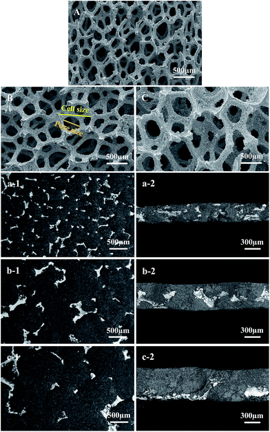 | ||
| Fig. 1 SEM images of metal foams and the surface and cross-section of electrodes. 450 μm cell size (A, a-1 and a-2), 800 μm cell size (B, b-1 and b-2), 1200 μm cell size (C, c-1 and c-2). | ||
As is shown in Fig. 2(a), the cell capacity exhibited higher at a lower current density in the case of larger cell size of metal foam because the mass loading of the active material is much higher for the larger cell size of metal foam; for example, each capacity of cell using 450, 800, 1200 μm cell size of metal foams is 5.1, 7.2 and 8.8 mA h cm−2, respectively at 1 mA cm−2. It should be noted that there is almost no difference in specific capacity at lower current rate, which was close to theoretical capacity. However, the cell capacity decreased much more for the cell using lager cell size of metal foam especially for the 1200 μm at higher current density. The capacity of cell using 1200 μm cell size of metal foam was not the largest any more when the current density was more than 3 mA cm−2 and there was almost no big difference in the capacity comparing with the cell using 450 μm cell size of metal foam when the current density was more than 5 mA cm−2. Additionally, the coulombic efficiency of the cell using 1200 μm cell size of metal foam was much worse than in the case of the smaller cell size of metal foam in the range of 2–6 mA cm−2. The current rate performance of the cells was also evaluated as is shown in Fig. 2(b). In lower current rate, there was almost no difference in specific capacity for the cells regardless of cell size of metal foams because there was no difference in diffusion limitation of Li-ion. However, in higher current rate, the diffusion limitation causes more for the thicker electrode. Additionally, the charge transfer ability decreased because the triple contact area per active material mass was much smaller and the average distance between the metal frame and the active material particles was much longer for the cell using the larger cell size of metal foam. According to the results, the cell using 1200 μm cell size of metal foam showed relatively poor rate performance comparing with the cells using 450 and 800 μm cell size of metal foams. For instance, at 1.0 C-rate, the specific capacity was only 40 mA h g−1 for the cell using 1200 μm cell size of metal foam, whereas it was 100 and 80 mA h g−1, respectively for the cell using 450 and 800 μm cell size of metal foams.
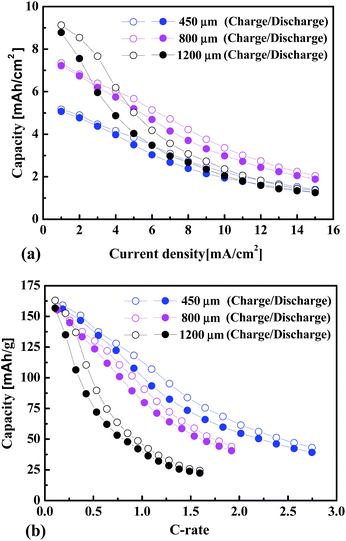 | ||
| Fig. 2 Variation in the cell capacity and specific capacity with an increase in current density (a) and C-rate (b), for the cells using different cell size of metal foams. | ||
As shown in Fig. 3(a), there was no difference in power performance in plateau region for the cells using the different cell size of metal foam current collectors because the over-potential was almost the same in that region at lower current density (2 mA cm−2). However, at higher current density, for example at 11 mA cm−2 as shown in Fig. 3(b), the over-potential of cell using 1200 μm cell size of metal foam increased much faster compared with the cells using the smaller cell size of metal foams because of the diffusion limitation of Li-ion and the higher charge transfer resistance. As shown in Fig. 4, there was no significant difference in bulk resistance for the cells. However, the charge transfer resistance difference between the cells using 450 and 800 μm cell size of metal foams was 1.5 Ω cm2 and it was 8 Ω cm2 between the cells using 450 and 1200 μm cell size of metal foams. Additionally, the slope of straight line scanned at lower frequencies, which has relation with diffusion limitation was much lower for the 1200 μm cell than in the case of the smaller cell size of metal foams. When the impedance was calculated using a unit of “Ω cm2”, both the redox area and electronic conductivity of electrode should be considered (the electrode density was controlled very carefully during the calendering process to avoid the effect of electrode density on the electronic conductivity. The electrode density was around 1.35 g cm−3 for the electrodes and the calculation method can be found in previous study9). For the thick electrode, the redox area was much larger due to the higher mass loading of active material that can result in lower impedance (the redox area of electrode equals to the total junction area between active material particles and electrolyte in the case of lower current rate and the effective redox area decreased in the case of higher current rate due to the diffusion limitation of Li-ion). However, the lower electronic conductivity can result in higher impedance due to the increase of cell size of metal foam. Thus, it is possible that there was no significant difference in impedance for the cells using 450 and 800 μm cell size of metal foams. The equivalent circuit was obtained by fitting the impedance spectra as shown in the inset of Fig. 4. Yao et al. also reported the same result by using Ni–Cr alloy foam current collector.24 Rb, RCT, ZW, Cdl represent the ohmic resistance, charge transfer resistance, the Warburg impedance, and the capacitance of double layer, respectively. Although the mass loading of the active material was the largest for the 1200 μm cell size of metal foam, the deterioration of capacity and the voltage drop in the plateau region were relatively much more because of the higher charge transfer resistance and diffusion limitation of Li-ion. If the cell performance was evaluated in current rate, obviously, the rate performance was better for the cell using smaller cell size of metal foam as shown in Fig. 3(c) and (d).
 | ||
| Fig. 3 Comparison of the charge–discharge curves at 2 mA cm−2 (a), 11 mA cm−2 (b), 0.6 C-rate (c) and 1.3 C-rate (d) for the cells using different cell size of metal foams. | ||
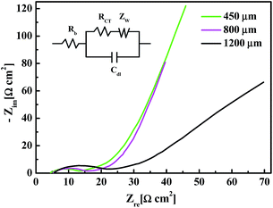 | ||
| Fig. 4 Comparison of the AC impedance curves for the cells using different cell size of metal foams. | ||
The electrochemical performance of cells was also evaluated by cyclic voltammetric analysis. As is shown in Fig. 5, the redox peak of cell using smaller cell size of metal foam occurred earlier and the specific current of peak was higher; however, it should be noted that the specific current of peak was much smaller and the shape of peak was much broader for the cell using 1200 μm cell size of metal foam. Due to the lower charge transfer ability, the Li concentration gradient was much lower at the electrode surface for the 1200 μm cell, thus the specific diffusion flux of Li was also much lower according to the Fick's 1st law. Additionally, the higher diffusion limitation of Li ion occurred because of the thickness of electrode.25,26 As shown in the curves, the difference in reduction current of peak between the 450 and 800 μm cells was 18 mA g−1, whereas the difference was as much as 73 mA g−1 between the 450 and 1200 μm cells. It indicates that much higher voltage difference was needed between the applied voltage and open circuit voltage (OCV) to insert or extract the same amount of Li for the large cell size of electrode.
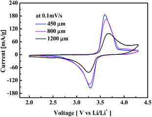 | ||
| Fig. 5 Comparison of the cyclic voltammetric curves for the cells using different cell size of metal foams. | ||
The cycle-life performance of cells using the different cell size of metal foams was evaluated at 0.3 C as is shown in Fig. 6. After 50 cycles, the cell using smaller cell size of metal foam exhibited slightly better cycle stability; however, each cell capacity faded less than 10% of their capacity. The good cycle-life performance indicates that the tolerance of NiCrAl foam was sufficiently high enough. Additionally, the high tolerance of NiCrAl foam was confirmed by CV measurement and the result showed that there was no anodic peak with a potential range of 2.0–5.0 V at a scan speed of 0.1 mV s−1. The tolerance was much higher than in the case of the Ni-35 wt% Cr alloy foam reported by Yao et al.24 and less content of Cr was needed by the addition of Al element in our study. Considering the cell capacity and rate performance, the cell size of metal foam between 450 and 800 μm can be considered for commercial application especially for the large scale energy storage. However, the main issue in this study was that the metal foams manufactured for the emission control of vehicle engines were much heavier than the commercial foil type current collectors. To solve the issue, the thickness of Ni electroplated on the polyurethane and the weight ratio of Ni, Cr and Al in metal foam should be controlled effectively to reduce the weight as much as possible for Li-ion batteries. Additionally, the specific surface area and the electric resistance of metal foam should also be considered. Currently, the electrode using a foil type usually was packed by rolling process, especially for the portable devices. However, when the electrode surface is large, some of the commercial Li-ion battery electrodes are packed via layered stacking. In our case, the thick electrode using metal foam should be packed by layered stacking to avoid the bending issue.
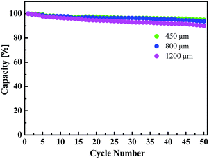 | ||
| Fig. 6 Comparison of the cycle-life performance for the cells using different cell size of metal foams. | ||
D Conclusions
Ultra-thick Li-ion battery electrodes were prepared successfully in the range of 300–600 μm by using different cell size of metal foam current collectors. Although the electrode using 1200 μm cell size of metal foam possesses the highest mass loading of active material, the cell capacity becomes lower than the cell using 800 μm cell size of metal foam when the current density was higher than 3 mA cm−2. The AC impedance analysis showed that there was almost no difference in bulk resistance for the cells; however, higher charge transfer resistance and the lower slope of straight line scanned at lower frequencies were observed for the cell using 1200 μm cell size of metal foam. Considering both of the cell capacity and rate performance, the cell size of metal foam between 450 and 800 μm is promising for large scale energy storage.Acknowledgements
This research was supported by Research Institute of Advanced Materials and Eui-San Research Center at Seoul National University. The authors acknowledge the support of metal foam from Alantum Corporation and lithium iron phosphate from Hanwha Chemical Corporation.Notes and references
- J. M. Tarascon and M. Armand, Nature, 2001, 414, 359–367 CrossRef CAS PubMed.
- K. Kang, Y. S. Meng, J. Breger, C. P. Grey and G. Ceder, Science, 2006, 311, 977–980 CrossRef CAS PubMed.
- B. L. Ellis, K. T. Lee and L. F. Nazar, Chem. Mater., 2010, 22, 691–714 CrossRef CAS.
- G. F. Yang, J. S. Song, H. Y. Kim and S. K. Joo, Jpn. J. Appl. Phys., 2013, 52, 10MB13 CrossRef.
- V. Etacheri, R. Marom, R. Elazari, G. Salitra and D. Aurbach, Energy Environ. Sci., 2011, 4, 3243–3262 CAS.
- Y. Li, J. Song and J. Yang, Renewable Sustainable Energy Rev., 2014, 37, 627–633 CrossRef PubMed.
- S. B. Chikkannanavar, D. M. Bernardi and L. Liu, J. Power Sources, 2014, 248, 91–100 CrossRef CAS PubMed.
- J. S. Wang, P. Liu, E. Sherman, M. Verbrugge and H. Tataria, J. Power Sources, 2011, 196, 8714–8718 CrossRef CAS PubMed.
- G. F. Yang, K. Y. Song and S. K. Joo, J. Mater. Chem. A, 2014, 2, 19648–19652 CAS.
- H. Liu, Q. Cao, L. J. Fu, C. Li, Y. P. Wu and H. Q. Wu, Electrochem. Commun., 2006, 8, 1553–1557 CrossRef CAS PubMed.
- T. E. Ashton, J. V. Laveda, D. A. MacLaren, P. J. Baker, A. Porch, M. O. Jones and S. A. Corr, J. Mater. Chem. A, 2014, 2, 6238 CAS.
- W.-B. Luo, S.-L. Chou, Y.-C. Zhai and H.-K. Liu, J. Mater. Chem. A, 2014, 2, 4927 CAS.
- Y. Ding, Y. Jiang, F. Xu, J. Yin, H. Ren, Q. Zhuo, Z. Long and P. Zhang, Electrochem. Commun., 2010, 12, 10–13 CrossRef CAS PubMed.
- Z. Chen and J. R. Dahn, J. Electrochem. Soc., 2002, 149, A1184 CrossRef CAS PubMed.
- F. Gao, Z. Tang and J. Xue, Electrochim. Acta, 2007, 53, 1939–1944 CrossRef CAS PubMed.
- K. Kim, J. H. Jeong, I.-J. Kim and H.-S. Kim, J. Power Sources, 2007, 167, 524–528 CrossRef CAS PubMed.
- D. Jugović, M. Mitrić, M. Kuzmanović, N. Cvjetićanin, S. Marković, S. Škapin and D. Uskoković, Powder Technol., 2012, 219, 128–134 CrossRef PubMed.
- Y. Zhang, L. Chen, J. Ou, J. Wang, B. Zheng, H. Yuan, Y. Guo and D. Xiao, J. Mater. Chem. A, 2013, 1, 7933 CAS.
- Z.-X. Chi, W. Zhang, F.-Q. Cheng, J.-T. Chen, A.-M. Cao and L.-J. Wan, RSC Adv., 2014, 4, 7795 RSC.
- Z. Bi, X. Zhang, W. He, D. Min and W. Zhang, RSC Adv., 2013, 3, 19744 RSC.
- C. Jin, X. Zhang, W. He, Y. Wang, H. Li, Z. Wang and Z. Bi, RSC Adv., 2014, 4, 15332 RSC.
- Y. Jiang, S. Liao, Z. Liu, G. Xiao, Q. Liu and H. Song, J. Mater. Chem. A, 2013, 1, 4546 CAS.
- P. Yan, L. Lu, X.-m. Liu, Y. Cao, Z.-p. Zhang, H. Yang and X.-d. Shen, J. Mater. Chem. A, 2013, 1, 10429 CAS.
- M. Yao, K. Okuno, T. Iwaki, M. Kato, S. Tanase, K. Emura and T. Sakai, J. Power Sources, 2007, 173, 545–549 CrossRef CAS PubMed.
- H. Zheng, J. Li, X. Song, G. Liu and V. S. Battaglia, Electrochim. Acta, 2012, 71, 258–265 CrossRef CAS PubMed.
- S. Yu, S. Kim, T. Y. Kim, J. H. Nam and W. I. Cho, J. Appl. Electrochem., 2012, 43, 253–262 CrossRef.
| This journal is © The Royal Society of Chemistry 2015 |
