An anion-exchange strategy for 3D hierarchical (BiO)2CO3/amorphous Bi2S3 heterostructures with increased solar absorption and enhanced visible light photocatalysis†
Fan Dong*a,
Xin Fenga,
Yuxin Zhangb,
Chunfeng Gaoa and
Zhongbiao Wu*c
aChongqing Key Laboratory of Catalysis and Functional Organic Molecules, College of Environmental and Biological Engineering, Chongqing Technology and Business University, Chongqing, 400067, China. E-mail: dfctbu@126.com; Fax: +86-23-62769785 ext. 605; Tel: +86-23-62769785 ext. 605
bCollege of Materials Science and Engineering, Chongqing University, Chongqing, 400044, P. R. China
cDepartment of Environmental Engineering, Zhejiang University, Hangzhou, Zhejiang 310027, China. E-mail: zbwu@zju.edu.cn
First published on 9th January 2015
Abstract
Bismuth-based nanostructured materials have attracted great interest in a wide range of applications. In the present work, 3D (BiO)2CO3 hierarchical microspheres self-assembled by nanosheets were synthesized by a simple hydrothermal method. By using a facile anion-exchange strategy, (BiO)2CO3/amorphous Bi2S3 heterostructures were constructed through the controlled chemical reaction between (BiO)2CO3 microspheres and Na2S in an aqueous solution. The as-prepared samples were systematically characterized by XRD, SEM-EDX, TEM, FT-IR, XPS, UV-vis DRS and PL techniques. The heterostructured samples were applied for photocatalytic removal of ppb-level NO in air under visible light irradiation. The pure (BiO)2CO3 hierarchical microspheres exhibited decent visible light photocatalytic activity due to the surface reflecting and scattering effect. Amorphous Bi2S3 showed no photocatalytic activity due to narrow band gap. By hybridization of (BiO)2CO3 microspheres with amorphous Bi2S3 on the surface, 3D hierarchical (BiO)2CO3/amorphous Bi2S3 heterostructures were constructed, which demonstrated increased solar light absorption and highly enhanced visible photocatalytic activity and stability. The enhanced performance can be directly ascribed to the increased visible light utilization, promoted charge separation arising from the well-matched band structure and accelerated reactants transfer resulting from special 3D hierarchical structure. The present work opens a new avenue for modification of wide-band gap semiconductor with amorphous components, which could reduce the further thermal treatment and production cost.
1. Introduction
In recent years, bismuth-based nanostructured materials have received great attention due to their potential applications in photocatalysts, semiconductor technology, thermal catalysts, energy conversion and electronics.1–4 Especially, a bismuth-based semiconductor nanohybrid with a staggered alignment of band edges at the heterointerface could greatly extend the spectral responsive range of a wide-band gap semiconductor and significantly reduce the recombination of the photogenerated electrons and holes, thus effectively improving the photocatalytic activity of a single-component material.5–9 Up to now, various kinds of Bi-based heterostructures have been synthesized, such as BiOCl/Bi2S3,10 BiVO4/Bi2S3,11 BiOI/Bi2S3,12 (BiO)2CO3/BiOI,13 BiOI/BIOCl,14 Bi2MoO6/BiOCl (ref. 15) and so on.Hierarchical bismuth-containing materials composed of 2D nanosheets or nanoplates have been developed and exhibited excellent visible light photocatalytic performance, such as Bi2WO6, Bi2MoO6, BiVO4, BiOX (X = Br, I), BiFeO3, Bi2Ti2O7, Bi2Sn2O7 and (BiO)2CO3.16–28 These 2D nanostructures can be acted as building blocks for construction of 3D architectures. 3D architectures favored the transfer of electrons and holes generated inside the crystal surface and promoted charge separation, which could enhance the photocatalytic activity.14,28–30 Recently, (BiO)2CO3 is found to be an emergent attractive photocatalyst.28–33 However, pure (BiO)2CO3 with large band gap (3.1–3.5 eV) can only be excited by UV light.31–33 Thus, it is important to extend the light absorption spectra of (BiO)2CO3 into visible light region so that the modified (BiO)2CO3 could utilize the abundant solar light. Nitrogen doping,29,30,33 silver decoration,25,32 and formation of heterojunction26,27,34 have been employed to achieve this goal.
(BiO)2CO3 has a typical layered structure with alternative stacking of (BiO)22+ sheets interleaved by CO32− groups.29–32 This special crystal structure could behave as an excellent host material for further modification. Firstly, we must find out a semiconductor that has a low solubility parameter and narrow band gap, which could combine with (BiO)2CO3 through anion change. The combination of two semiconductors with different energy levels could form an effective heterostructure with enhanced charge separation.9,11,35–38 Fortunately, Bi2S3 is a such semiconductor that could fulfill the requirements. Bi2S3 is direct semiconductor with a narrow band gap (∼1.3 eV). It has many applications such as thermoelectrics, photovoltaics, X-ray computed tomography, and electrochemical hydrogen storage.39–42 The solubility constant (Ksp) of Bi2S3 (1 × 10−97) is much lower than that of (BiO)2CO3 (3.98 × 10−36). On the basis of the precipitation and dissolution equilibrium, product with higher solubility product constant (Ksp) will be converted into product with lower Ksp in solution, which is also called ion exchange reaction. Although (BiO)2CO3/Bi2S3 has been reported, the Bi2S3 component on the surface of (BiO)2CO3 is well crystallized by hydrothermal treatment.43–45
In the present work, to promote the photocatalytic activity of (BiO)2CO3 under visible light irradiation, we developed an anion-exchange strategy for the construction of 3D hierarchical (BiO)2CO3/amorphous Bi2S3 heterostructures with increased solar absorption and enhanced visible light photocatalytic performance. The (BiO)2CO3/amorphous Bi2S3 heterostructures were constructed by a facile anion exchange reaction between (BiO)2CO3 and Na2S. As the Ksp of Bi2S3 is lower than that of (BiO)2CO3, part of (BiO)2CO3 could be converted into Bi2S3 easily in the presence of Na2S. The content of Bi2S3 can be controlled by the amount of Na2S. The photocatalytic activity of the obtained (BiO)2CO3/amorphous Bi2S3 heterostructures was evaluated for removal of NO at ppb-level under visible light. Significantly, the as-prepared heterostructured photocatalysts exhibited highly enhanced visible light activity and photochemical stability during photocatalytic removal of NO in air, which can be directly ascribed to the formation of heterostructures and special 3D hierarchical structure. The construction of heterostructures by amorphous Bi2S3 has significant advantages of facile synthesis and low cost. The present work could shed new light on the fabrication of high-performance heterostructured photocatalysts by modification with amorphous component.
2. Experimental section
2.1 Synthesis of (BiO)2CO3 hierarchical microspheres
All chemicals used in this study were analytical grade and were used without further purification. In a typical fabrication, sodium carbonate (0.46 g) were added with 70 mL distilled water into a 100 mL autoclave Teflon vessel and stirred for 10 min. Then bismuth citrate (1.60 g) was added to the solution and stirred for another 30 min. The resulted aqueous precursor suspension was then hydrothermally treated at 160 °C for 24 h. The obtained solid sample was filtered, washed with water and ethanol for three times, and dried at 60 °C to get final (BiO)2CO3 (hereinafter referred to BOC).2.2 Construction of (BiO)2CO3/amorphous Bi2S3 heterostructures
In a typical process, 0.75 g of (BiO)2CO3 was added into 60 mL distilled water, and then ultrasound dispersed for 30 min. The aqueous suspension was put into thermostat water bath at 60 °C and stirring. Then the 40 mL of Na2S aqueous solution was added to the above solution under continuous stirring for another 2 h. The sample obtained was filtered, washed with water and ethanol for four times and dried at 60 °C to get the final products. The amount of Na2S in the solution is controlled at 0.0175, 0.0350, 0.0875, 0.1750 and 0.3500 g, respectively. The molar ratio of Bi2S3 to (BiO)2CO3 is 0.05, 0.10, 0.25, 0.50 and 1.0, respectively. Accordingly, the resulted products were labeled as BS-0.05, BS-0.10, BS-0.25, BS-0.50 and BS-1.00, respectively.2.3 Characterization methods
The crystal structure of the as-obtained sample were analyzed by X-ray diffraction with Cu-Kα radiation (XRD: model D/max RA, Rigaku Co., Japan). The morphological structure were examined by transmission electron microscopy (TEM: JEM-2010, Japan). X-ray photoelectron spectroscopy with Al Kα X-rays (hν = 1486.6 eV) radiation operated at 150 W (XPS: Thermo ESCALAB 250, USA) was used to investigate the surface properties. The shift of the binding energy due to relative surface charging was corrected using the C1s level at 284.8 eV as an internal standard. The Brunauer–Emmett–Teller (BET) surface area and the pore size distribution of the products were identified by a Micromeritics ASAP 2020 apparatus. All the samples were degassed at 150 °C prior to measurements. The UV-vis diffuse reflection spectra were obtained for the dry-pressed disk samples using a Scan UV-vis spectrophotometer (UV-vis DRS: UV-2450, China) equipped with an integrating sphere assembly, using 100% BaSO4 as reflectance sample. FT-IR spectra were recorded on a Nicolet Nexus spectrometer on samples embedded in KBr pellets. The solid-state photoluminescence (PL) spectra were measured with fluorescence spectrophotometer (PL: FS-2500, Japan) using a Xe lamp as an excitation source with optical filters.2.4 Evaluation of visible light photocatalytic performance
The photocatalytic activity of the resulting samples was investigated by oxidation of NO at ppb levels in a continuous flow reactor at ambient temperature. The volume of the rectangular reactor, which was made of stainless steel and covered with Saint-Glass, was 4.5 L (30 cm × 15 cm × 10 cm). A 150 W commercial tungsten halogen lamp was vertically placed outside the reactor above the reactor. Adequate distance was also kept from the lamp to the reactor for the same purpose to keep the temperature at a constant level. For the visible light photocatalytic activity test, UV cutoff filter (420 nm) was adopted to remove UV light. For each photocatalytic activity test experiment, two sample dishes (with a diameter of 12 cm) containing the photocatalyst powders was placed in the center of the reactor. The photocatalyst samples were prepared by coating an aqueous suspension of the samples onto the glass dish and then dried at 60 °C. The weight of the photocatalysts used for each dish was kept at 0.10 g. The NO gas was acquired from a compressed gas cylinder at a concentration of 100 ppm of NO (N2 balance). The initial concentration of NO was diluted to 550 ppb by the air stream supplied by purified air. The desired relative humidity (RH) level of the NO flow was controlled at 60% by passing the zero air streams through a humidification chamber. The gas streams were premixed completely by a gas blender, and the flow rate was controlled at 3.3 L min−1 by a mass flow controller. After the adsorption–desorption equilibrium was achieved, the lamp was turned on. The concentration of NOx was continuously measured by a chemiluminescence NOx analyzer (Thermo Environmental Instruments Inc., 42i-TL), which monitors NO, NO2, and NOx (NOx represents NO + NO2) with a sampling rate of 1.0 L min−1. The NO removal ratio (η) was calculated as η(%) = (1 − C/C0) × 100%, where C and C0 are concentrations of NO in the outlet steam and the feeding stream, respectively.3. Results and discussion
3.1 Phase structure
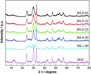
The solubility of Bi2S3 is much lower than that of (BiO)2CO3. Thus, with the presence of S2− ions, part of (BiO)2CO3 could transform into Bi2S3 rapidly, resulting in the formation of (BiO)2CO3/amorphous Bi2S3 composites. Fig. 1 presents the XRD patterns of pure (BiO)2CO3 and (BiO)2CO3/Bi2S3 with different Bi2S3 contents. The diffraction peaks of all the samples are sharp and intense. All the peaks detected can be indexed to (BiO)2CO3 (JCPDS-ICDD Card no. 41-1488). No peaks of any other phases or impurities can be observed. The intensity of diffraction peaks of (BiO)2CO3/amorphous Bi2S3 samples is gradually decreased as the content of Bi2S3 is increased. However, from the XRD patterns, no significant peaks of Bi2S3 can be detected, which indicates that Bi2S3 is amorphous. As the Bi2S3 component is amorphous and exhibits no diffraction peaks, the inclusion of amorphous Bi2S3 into the composites would result in lowered diffraction intensity. When the content of amorphous Bi2S3 is increased, the diffraction peaks of the composites samples would be decreased. By hydrothermal treatment of the anion-exchange process, the (BiO)2CO3/crystalline Bi2S3 can be obtained (Fig. S1†). This fact further suggests the presence of amorphous Bi2S3 on the surface of (BiO)2CO3 under ambient anion-exchange process.3.2 Chemical composition
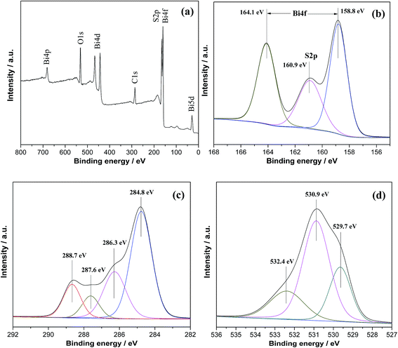
In order to confirm the chemical state of the elements in the sample, XPS were carried out. Fig. 2a shows the wide-scan XPS spectra of BS-0.25, in which Bi, S, O and C elements can be observed. In Fig. 2b, we can see two strong peaks at 164.1 and 158.8 eV that are corresponded to Bi 4f5/2 and Bi 4f7/2 of Bi3+ in the sample. The peak at 160.9 eV can be assigned to the binding energy of the S2p orbital in the form of S2−, which also indicates the formation of Bi2S3.12 Fig. 2c shows the XPS spectra for C1s, where the peaks centered at 284.8, 286.3, 287.6, and 288.7 eV can be attributed to C–C, C–O, C![[double bond, length as m-dash]](https://www.rsc.org/images/entities/char_e001.gif) O and O
O and O![[double bond, length as m-dash]](https://www.rsc.org/images/entities/char_e001.gif) C–O groups, respectively.46,47 The O1s spectra (Fig. 2d) are also recorded, which can be fitted by three peaks at binding energies of 529.7, 530.9 and 532.4 eV, respectively. The peak at 530.9 eV is characteristic of Bi–O binding energy in (BiO)2CO3, and the other two peaks at 529.7 and 532.4 eV can be assigned to carbonate species and adsorbed H2O on the surface.32 From the XPS spectra, it can be concluded that the heterostructure consist of (BiO)2CO3 and Bi2S3 with no other residual impurities.
C–O groups, respectively.46,47 The O1s spectra (Fig. 2d) are also recorded, which can be fitted by three peaks at binding energies of 529.7, 530.9 and 532.4 eV, respectively. The peak at 530.9 eV is characteristic of Bi–O binding energy in (BiO)2CO3, and the other two peaks at 529.7 and 532.4 eV can be assigned to carbonate species and adsorbed H2O on the surface.32 From the XPS spectra, it can be concluded that the heterostructure consist of (BiO)2CO3 and Bi2S3 with no other residual impurities.
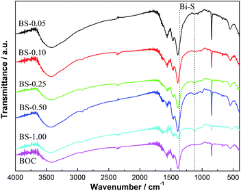
FT-IR spectra of (BiO)2CO3 and (BiO)2CO3/amorphous Bi2S3 samples are shown in Fig. 3. The two peaks at 3389 and 1730 cm−1 can be attributed to the stretching and deformation vibrations of the O–H groups of the chemisorbed and/or physisorbed water molecules. Four characteristic band groups of CO32− at 1067 cm−1 (symmetric stretching mode ν1), 846 and 820 cm−1 (out-of plane bending mode ν2), 1468 and 1391 cm−1 (antisymmetric vibration ν3), 670 cm−1 (in-plane deformation ν4), and 1756 and 1730 cm−1 (ν1 + ν4) are observed for all the samples.48 The peak at 2373 cm−1 derived from the vibration of the CO32− is also observed. The peaks at 1382 and 1103 cm−1 can be assigned to the Bi–S bond vibrations arising from amorphous Bi2S3.12 The peak at 1382 cm−1 is overlapped with the peak of CO32− (1391 cm−1), so the change of this peak cannot be observed directly. Further observation of the peak at 1103 cm−1 indicates that the intensity of this peak is slightly increased with the increased amount of Bi2S3.
3.3 Morphological structure
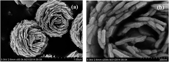
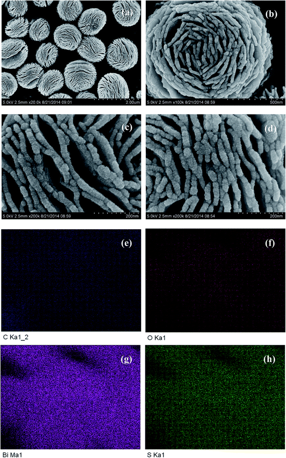
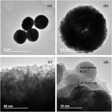
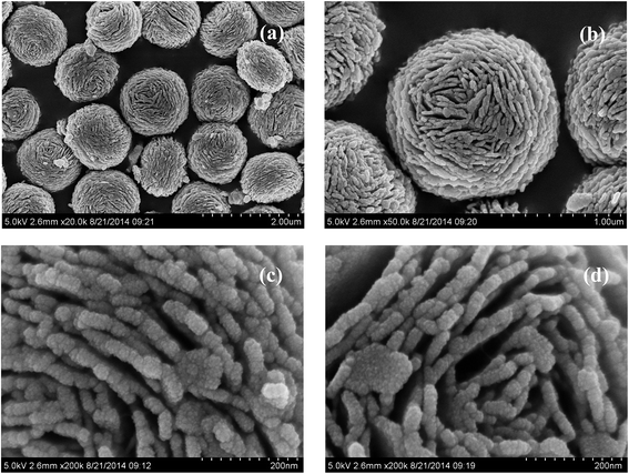
Fig. 4a and b shows the SEM images of pure (BiO)2CO3 sample, which consists of many three-dimensional (3D) flower-like hierarchical microspheres self-assembled by two-dimensional (2D) interleaved nanosheets.32 The sizes of the microspheres range from 0.7 to 1.3 μm. After reacting with Na2S, the morphology of (BiO)2CO3 has not changed obviously (Fig. 5a–d). Further observation in Fig. 5c and d shows that there are some particles deposited uniformly on the surface of the nanosheets. These particles should be amorphous Bi2S3. The EDX maps (Fig. 5e–h) indicate the elemental distribution of C, O, Bi and S. Obviously, amorphous Bi2S3 are homogeneously distributed on the surface of the (BiO)2CO3/Bi2S3 heterostructures. The TEM images (Fig. 6a and b) shows the microsphere morphology of BS-0.25. Fig. 6c shows the local region of one microsphere and some particles can be observed on the surface. From the HRTEM image (Fig. 6d), the lattice spacing of 0.292 nm can be well assigned to the (013) plane of (BiO)2CO3. The lattice of Bi2S3 cannot be observed as Bi2S3 is amorphous, which is consistent with XRD. The amorphous Bi2S3 is attached on the surface (Fig. 6d), indicating the anion-exchange reaction takes place on the surface of the nanosheets. The generation of amorphous Bi2S3 results in the formation of (BiO)2CO3/amorphous Bi2S3 heterostructure.43Fig. 7 shows the SEM images of BS-1.00. When the amount of Na2S is increased to 50%, more Bi2S3 particles will be produced. The microsphere morphology does not change, however, some large particles are attached on the surface (Fig. 7a and b), which can be ascribed to the aggregation of small Bi2S3 nanoparticles. The increased content of amorphous Bi2S3 on the surface of (BiO)2CO3 microspheres leads to the decreased peak intensity in the XRD pattern (Fig. 1). The formation process of 3D (BiO)2CO3/amorphous Bi2S3 heterostructured hierarchical microspheres by anion exchange process is shown in Scheme 1.
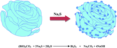 | ||
| Scheme 1 Formation of 3D (BiO)2CO3/amorphous Bi2S3 heterostructured hierarchical microspheres by a controllable anion exchange process. | ||
Nitrogen adsorption–desorption measurement was used to study the Brunauer–Emmett–Teller (BET) surface areas and the corresponding pore size distribution of pure (BiO)2CO3 and (BiO)2CO3/amorphous Bi2S3 heterostructures. According to the Brunauer–Deming–Deming–Teller (BDDT) classification, the majority of physisorption isotherms can be classified into six types. As showed in Fig. 8a, all the samples have an isotherm of type IV, which indicates the presence of mesopores. Comparing with BOC, the heterostructured samples display a higher absorption at the relatively high pressure, indicating the presence of more mesopores.49,50 The surface areas and pore volumes of all the samples are shown in Table 1. The slightly increased surface areas and pore volumes of heterostructured samples is associated with the formation of amorphous Bi2S3 on the surface. Furthermore, the shape of the hysteresis loops is of type H3, implying the existence of slit-like pores, which is consistent with the TEM observations. The corresponding pore size distribution (PSD) curves of the samples are shown in Fig. 8b. The PSD curves range from 2 to 100 nm and is bimodal with small mesopores (3.2–2.7 nm) and larger ones (7.2–10.8 nm). The small mesopores can be ascribed to the pores formed among the aggregated BOC nanosheets and Bi2S3 nanoparticles, and the large mesopores are ascribed to the pores formed between the stacked microspheres.32
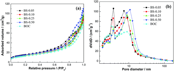 | ||
| Fig. 8 N2 adsorption–desorption isotherms (a) and pore size-distribution curves (b) of BOC and (BiO)2CO3/amorphous Bi2S3 heterostructures. | ||
| Sample name | SBET (m2 g−1) | Pore volume (cm3 g−1) | Peak pore diameter (nm) | NO η (%) |
|---|---|---|---|---|
| BOC | 46 | 0.122 | 3.2/8.9 | 21.5 |
| BS-0.05 | 56 | 0.147 | 3.7/7.2 | 48.6 |
| BS-0.10 | 50 | 0.143 | 3.6/7.3 | 51.4 |
| BS-0.25 | 49 | 0.150 | 3.6/9.0 | 57.1 |
| BS-0.50 | 54 | 0.171 | 3.7/10.8 | 45.1 |
3.4 Optical property and band structure
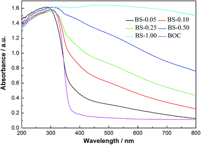
The pure BOC and (BiO)2CO3/amorphous Bi2S3 heterostructures with the increasing of molar ratio of Bi2S3 show a gradient color deepening from white to black. From the UV-vis absorption spectra (Fig. 9), we can see that the pure BOC displayed the absorption edge around 370 nm. With the increasing molar ratio of Bi2S3 from 0.05 to 1.00, the light absorption spectra of the heterostructured samples are broadened dramatically from UV to the whole visible light region. This interesting observation can be owing to the special properties of Bi2S3 with small band gap, large absorption coefficient and strong absorption in nearly all the visible light range. The increased solar absorption is beneficial for enhancement of photocatalytic activity.The band-edge positions of the semiconductors in the heterostructures have a pivotal influence on charge separation and transfer. The valence band (VB) edge of a semiconductor at the point of zero charge can be calculated by the empirical equation EVB = X − Ee +0.5Eg, where EVB is the valence band-edge potential, X is the electronegativity of the semiconductor expressed as the geometric mean of the absolute electronegativity of the constituent atoms, Ee is the energy of free electrons on the hydrogen scale (about 4.5 eV), and Eg is the band-gap energy of the semiconductor.51,52 The conduction band (CB) edge ECB can be determined by ECB = EVB − Eg. The X values for (BiO)2CO3 and Bi2S3 are 6.36 and 5.27 eV, respectively. The band-gap energies of (BiO)2CO3 and Bi2S3 is 3.33 and 1.3 eV. From the equation above, the top of VB and the bottom of CB of (BiO)2CO3 and Bi2S3 can be calculated 0.20 and 3.53 eV for (BiO)2CO3; 0.12 and 1.41 eV for Bi2S3. The energy band levels of (BiO)2CO3/Bi2S3 heterostructures and the possible charge separation process are proposed in Scheme 1. Under visible light irradiation, Bi2S3 can be easily excited and electrons and holes are generated. For (BiO)2CO3 microspheres (SEM in Fig. 4), the special hierarchical structure could induce effects of multiple light surface scattering and reflecting (SSR effect) and increase the effective optical path-length of a photon and absorption probability.32 Thus, the electrons and holes pairs can also be produced for (BiO)2CO3 via the SSR effect.32 As the CB of Bi2S3 is more negative than that of (BiO)2CO3, the electrons on the CB of Bi2S3 can transfer to the CB of (BiO)2CO3 easily. As the CB of (BiO)2CO3 is more positive than that of Bi2S3, holes in (BiO)2CO3 will be migrated to the VB of Bi2S3. In this way, the photoinduced electrons and holes can be separated efficiently over the (BiO)2CO3/amorphous Bi2S3 heterostructures (Scheme 2).
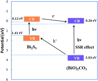 | ||
| Scheme 2 Diagram for energy band levels of (BiO)2CO3/amorphous Bi2S3 composites and the possible charge separation process. | ||
PL spectra are widely used to survey the recombination rate of the photogenerated electron–hole pairs. The decrease in the recombination rate gives rise to a low PL intensity. Fig. 10 shoes the PL emission spectra of BOC and (BiO)2CO3/amorphous Bi2S3 heterostructures at room temperature. The pure BOC shows a strong emission peak. After hybridization with amorphous Bi2S3, the PL intensity is greatly decreased. The PL intensity is decreased with the increased content of Bi2S3. The result implies that the combination of (BiO)2CO3 and Bi2S3 is powerful way to separate photogenerated electron–hole pairs.
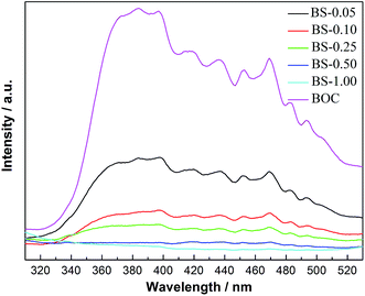 | ||
| Fig. 10 PL emission spectra of pure BOC and (BiO)2CO3/amorphous Bi2S3 heterostructures excited at 280 nm at room temperature. | ||
3.5 Photocatalytic activity and stability
The as-prepared samples were used to photocatalytic removal of ppb-level NO in gas phase in order to demonstrate their potential capability for air purification. Fig. 11a shows the variation of NO concentration (C/C0%) with irradiation time under visible light irradiation. NO could not be photolyzed under light irradiation (λ > 420 nm). Pure BOC shows NO removal ratio of 21% under visible light irradiation through SSR effect. When amorphous Bi2S3 is introduced, the resulted (BiO)2CO3/amorphous Bi2S3 heterostructures exhibit highly enhanced activity. Under optimized condition, BS-0.25 sample shows the most efficient activity with a NO removal ratio of 57.1%, which is even higher than that of N-doped (BiO)2CO3,29,30,33 BiOX (ref. 53 and 54) and C3N4 (ref. 55 and 56) under similar test conditions. When the molar ratio of Bi2S3 to (BiO)2CO3 is increased to 1.00, excessive amounts of Bi2S3 particles would cover all the surface of (BiO)2CO3. As a result, the BS-1.00 sample looses the activity. As all the samples have similar surface areas and morphology, the highly enhanced photocatalytic performance of (BiO)2CO3/Bi2S3 (BS-0.25) can be attributed to the heterostructures that effectively promote the separation of charge carriers and increase solar absorption that promotes the utilization of visible light. As the charge separation is promoted and the visible light utilization is broadened, more charges will take part in the photocatalytic reaction and more radicals will be produced. This could explain the inhibited NO2 generation during reaction (Fig. 11b), which is also beneficial for application as NO2 is more toxic. For the (BiO)2CO3/crystalline Bi2S3, the photocatalytic activity of is actually decreased, which indicates the significant advantages of (BiO)2CO3/amorphous Bi2S3.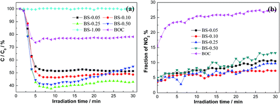 | ||
| Fig. 11 Visible light photocatalytic activity of pure BOC and (BiO)2CO3/amorphous Bi2S3 composites for NO removal (a) and evolution of NO2 in the outlet (b). | ||
The photochemical stability of a photocatalyst under repeated irradiation should be considered for practical applications. An excellent photocatalyst should maintain stable activity so that the catalyst can be used repeatedly. To test the stability, we conduct multiple runs of photocatalytic reaction for NOx removal. It can be seen from Fig. 12 that BS-0.25 exhibit an excellent stability in activity without deactivation under repeated irradiations.
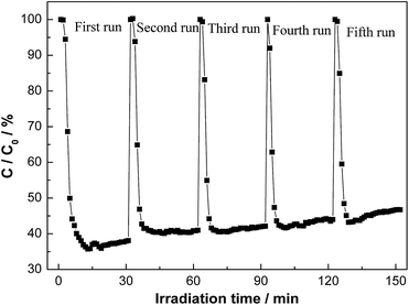 | ||
| Fig. 12 The repeated visible light photocatalytic activities of BS-0.25 for the removal of NO in air. | ||
4. Conclusion
In summary, we have synthesized 3D hierarchical (BiO)2CO3/Bi2S3 heterostructures by a facile anion-exchange method. Compared to others, our Bi2S3 was formed on the surface of (BiO)2CO3 hierarchical microspheres in amorphous form. The heterostructured photocatalysts exhibited drastically enhanced visible light photocatalytic activity and promoted oxidation of NO. The BS-0.25 has the maximal photocatalytic efficiency with a removal ratio of 57.1%, which is much higher than other types of photocatalyst. The combination of (BiO)2CO3 and amorphous Bi2S3 could extend the spectral responsive range of (BiO)2CO3 microspheres and promote the transfer of photogenerated carriers, leading to enhanced photocatalytic activities. This finding can be extended that the (BiO)2CO3 hierarchical microspheres are used as the substrate precursor and the structural template to combine with other components by ion exchange strategy. The present work could also open up a new avenue for construction of heterostructures by amorphous components.Acknowledgements
This research is financially supported by the National Natural Science Foundation of China (51108487 and 51478070), the Natural Science Foundation Project of CQ CSTC (cstc2013jcyjA20018), and the Science and Technology Project from Chongqing Education Commission (KJ1400617).References
- Z. F. Huang, L. Pan, J. Zhou, X. W. Zhang and L. Wang, Nanoscale, 2014, 6, 14044 RSC.
- L. S. Zhang, H. L. Wang, Z. G. Chen, P. K. Wong and J. S. Liu, Appl. Catal., B, 2011, 106, 1 CrossRef CAS PubMed.
- N. Zhang, R. Ciriminna, M. Pagliaro and Y. J. Xu, Chem. Soc. Rev., 2014, 43, 5276 RSC.
- X. B. Cao, Z. F. Lu, L. W. Zhu, L. Yang, L. Gu, L. L. Cai and J. Chen, Nanoscale, 2014, 6, 1434 RSC.
- L. W. Zhang and Y. F. Zhu, Catal. Sci. Technol., 2012, 2, 694 CAS.
- S. M. Sun and W. Z. Wang, RSC Adv., 2014, 4, 47136 RSC.
- J. Li, Y. Yu and L. Z. Zhang, Nanoscale, 2014, 6, 8473 RSC.
- H. F. Cheng, B. B. Huang and Y. Dai, Nanoscale, 2014, 6, 2009 RSC.
- X. H. Gao, H. B. Wu, L. X. Zheng, Y. J. Zhong, Y. Hu and X. W. Lou, Angew. Chem., Int. Ed., 2014, 53, 1 CrossRef.
- H. F. Cheng, B. B. Huang, X. Y. Qin, X. Y. Zhang and Y. Dai, Chem. Commun., 2012, 48, 97 RSC.
- D. K. Ma, M. L. Guan, S. S. Liu, Y. Q. Zhang, C. W. Zhang, Y. X. He and S. M. Huang, Dalton Trans., 2012, 41, 5581 RSC.
- J. Cao, B. Y. Xu, H. L. Lin, B. D. Luo and S. F. Chen, Dalton Trans., 2012, 41, 11482 RSC.
- L. Chen, S. F. Yin, S. L. Luo, R. Huang, Q. Zhang, T. Hong and P. C. T. Au, Ind. Eng. Chem. Res., 2012, 51, 6760 CrossRef CAS.
- F. Dong, Y. J. Sun, M. Fu, Z. B. Wu and S. C. Lee, J. Hazard. Mater., 2012, 219, 26 CrossRef PubMed.
- D. Yue, D. Chen, Z. Wang, H. Ding, R. Zong and Y. F. Zhu, Phys. Chem. Chem. Phys., 2014, 16, 26314 RSC.
- C. Zhang and Y. F. Zhu, Chem. Mater., 2005, 17, 3537 CrossRef CAS.
- L. W. Zhang, T. G. Xu, X. Zhao and Y. F. Zhu, Appl. Catal., B, 2010, 98, 138 CrossRef CAS PubMed.
- J. Yu and A. Kudo, Adv. Funct. Mater., 2006, 16, 2163 CrossRef CAS.
- X. Zhang, Z. H. Ai, F. L. Jia and L. Z. Zhang, J. Phys. Chem. C, 2008, 112, 747 CAS.
- Y. N. Huo, M. Miao, Y. Zhang, J. Zhu and H. X. Li, Chem. Commun., 2011, 47, 2089 RSC.
- Z. F. Bian, Y. N. Huo, Y. Zhang, J. Zhu and Y. F. Lu, Appl. Catal., B, 2009, 91, 247 CrossRef CAS PubMed.
- J. J. Wu, F. Q. Huang, X. J. Lü, P. Chen, D. Y. Wan and F. F. Xu, J. Mater. Chem., 2011, 21, 3872 RSC.
- Y. S. Xu and W. D. Zhang, Appl. Catal., B, 2013, 140, 306 CrossRef PubMed.
- L. Q. Ye, Y. R. Su, X. L. Jin, H. Q. Xie and C. Zhang, Environ. Sci.: Nano, 2014, 1, 90 RSC.
- S. J. Peng, L. L. Li, H. T. Tan, Y. Z. Wu, R. Cai, H. Yu, X. Huang, P. N. Zhu, S. Ramakrishna, M. Srinivasan and Q. Y. Yan, J. Mater. Chem. A, 2013, 1, 7630 CAS.
- P. Madhusudan, J. G. Yu, W. G. Wang, B. Cheng and G. Liu, Dalton Trans., 2012, 41, 14345 RSC.
- Y. L. Zhang, D. Y. Li, Y. G. Zhang, X. F. Zhou, S. J. Guo and L. B. Yang, J. Mater. Chem. A, 2014, 2, 8273 CAS.
- F. Dong, A. M. Zheng, Y. J. Sun, M. Fu, B. Q. Jiang, W. K. Ho, S. C. Lee and Z. B. Wu, CrystEngComm, 2012, 14, 3534 RSC.
- T. Xiong, F. Dong and Z. B. Wu, RSC Adv., 2014, 4, 56307 RSC.
- F. Dong, H. T. Liu, W. K. Ho, M. Fu and Z. B. Wu, Chem. Eng. J., 2013, 214, 198 CrossRef CAS PubMed.
- Y. Y. Liu, Z. Y. Wang, B. B. Huang, K. S. Yang, X. Y. Zhang, X. Y. Qin and Y. Dai, Appl. Surf. Sci., 2010, 257, 172 CrossRef CAS PubMed.
- F. Dong, Q. Y. Li, Y. Zhou, Y. J. Sun, H. D. Zhang and Z. B. Wu, Dalton Trans., 2014, 43, 9468 RSC.
- F. Dong, T. Xiong, R. Wang, Y. J. Sun and Y. K. Jiang, Dalton Trans., 2014, 43, 6631 RSC.
- W. D. Zhang, Y. J. Sun, F. Dong, W. Zhang, S. Duan and Q. Zhang, Dalton Trans., 2014, 43, 12026 RSC.
- L. Ma, W. Hu, Q. L. Zhang, P. Y. Ren, X. J. Zhuang, H. Zhou, J. Y. Xu, H. L. Li, Z. P. Shan, X. X. Wang, L. Liao, H. Q. Xu and A. L. Pan, Nano Lett., 2014, 14, 694 CrossRef CAS PubMed.
- S. J. Hong, S. Lee, J. S. Jang and J. S. Lee, Energy Environ. Sci., 2011, 4, 1781 CAS.
- X. F. Zhang, Y. Gong, X. L. Dong, X. X. Zhang, C. Ma and F. Shi, Mater. Chem. Phys., 2012, 136, 472 CrossRef CAS PubMed.
- S. Balachandran and M. Swaminathan, Dalton Trans., 2013, 42, 5338 RSC.
- S. C. Liufu, L. D. Chen, Q. Yao and C. F. Wang, Appl. Phys. Lett., 2007, 90, 112106 CrossRef PubMed.
- G. Konstantatos, L. Levina, J. Tang and E. H. Sargen, Nano Lett., 2008, 8, 4002 CrossRef CAS PubMed.
- O. Rabin, J. M. Perez, J. Grimm, G. Wojtkiewicz and R. Weissleder, Nat. Mater., 2006, 5, 118 CrossRef CAS PubMed.
- L. S. Li, N. J. Sun, Y. Y. Huang, Y. Qin, N. N Zhao, J. N. Gao, M. X. Li, H. H. Zhou and L. M. Qi, Adv. Funct. Mater., 2008, 18, 1194 CrossRef CAS.
- N. Liang, J. T. Zai, M. Xu, Q. Zhu, X. Wei and X. F. Qian, J. Mater. Chem. A, 2014, 2, 4208 CAS.
- X. F. Cao, L. Zhang, X. T. Chen and Z. L. Xue, CrystEngComm, 2011, 13, 1939 RSC.
- W. J. Wang, H. F. Cheng, B. B. Huang, X. J. Lin, X. Y. Qin, X. Y. Zhang and Y. Dai, J. Colloid Interface Sci., 2013, 6, 34 CrossRef PubMed.
- G. P. Dai, S. Q. Liu, Y. Liang and K. Liu, RSC Adv., 2014, 4, 34226 RSC.
- H. Xu, Y. X. Song, Y. H. Song, J. X. Zhu, T. T. Zhu, C. B. Liu, D. X. Zhao, Q. Zhang and H. M. Li, RSC Adv., 2014, 4, 34539 RSC.
- G. E. Tobon-Zapata, S. B. Etcheverry and E. J. Baran, J. Mater. Sci. Lett., 1997, 16, 656 CrossRef CAS.
- H. Q. Jiang, M. Nagai and K. Kobayashi, J. Alloys Compd., 2009, 479, 821 CrossRef CAS PubMed.
- H. Xu, H. M. Li, C. D. Wu, J. Y. Chu, Y. S. Yan, H. M. Shu and Z. Gu, J. Hazard. Mater., 2008, 153, 877 CrossRef CAS PubMed.
- M. C. Long, W. M. Cai, B. X. Zhou, X. Y. Chai and Y. H. Wu, J. Phys. Chem. B, 2006, 110, 20211 CrossRef CAS PubMed.
- M. A. Bulter and D. S. Ginley, J. Electrochem. Soc., 1978, 125, 228 CrossRef PubMed.
- W. D. Zhang, Q. Zhang and F. Dong, Ind. Eng. Chem. Res., 2013, 52, 6740 CrossRef CAS.
- Y. J. Sun, W. D. Zhang, T. Xiong, Z. W. Zhao, F. Dong, R. Q. Wang and W. K. Ho, J. Colloid Interface Sci., 2014, 418, 317 CrossRef CAS PubMed.
- F. Dong, M. Y. Ou, Y. K. Jiang, S. Guo and Z. B. Wu, Ind. Eng. Chem. Res., 2014, 53, 2318 CrossRef CAS.
- F. Dong, Z. Y. Wang, Y. J. Sun, W. K. Ho and H. D. Zhang, J. Colloid Interface Sci., 2013, 401, 70 CrossRef CAS PubMed.
Footnote |
| † Electronic supplementary information (ESI) available. See DOI: 10.1039/c4ra15798b |
| This journal is © The Royal Society of Chemistry 2015 |

