Anti-fouling performance and mechanism of anthraquinone/polypyrrole composite modified membrane cathode in a novel MFC–aerobic MBR coupled system
Lei Xu,
Guo-quan Zhang*,
Guang-en Yuan,
Hai-yan Liu,
Jia-dong Liu and
Feng-lin Yang
Key Laboratory of Industrial Ecology and Environmental Engineering, MOE, School of Environmental Science and Technology, Dalian University of Technology, Linggong Road 2, Dalian 116023, P. R. China. E-mail: guoquanz@126.com; Fax: +86 411 84706328; Tel: +86 411 84706328
First published on 23rd February 2015
Abstract
In this study, an aerobic membrane bioreactor (MBR) equipped with anthraquinone–disulphonate/polypyrrole (AQDS/PPY) composite modified polyester (PT) flat membrane serving as the cathode of a dual-chamber microbial fuel cell (MFC) was developed for wastewater treatment, energy recovery and membrane fouling mitigation. Various physicochemical characteristic parameters were investigated to determine the surface properties of the AQDS/PPY/PT membrane. During most of the operation period, the chemical oxygen demand and NH4+–N removal efficiencies of this novel MFC–MBR coupled system averaged 92.5% and 70.6%, respectively. Over the hydraulic retention time of 11.58 h and the external resistance of 1000 Ω, a maximum power density of 0.35 W m−3 and a current density of 2.62 A m−3 were obtained, meanwhile, the membrane fouling mitigation achieved the best status the H2O2 concentration in membrane effluent also reached the highest value of 2.1 mg L−1. The effective membrane fouling mitigation was attributed mainly to the continuous self-generated bio-electricity of MFC, which not only accelerates the back-diffusion of negative charged foulants away from the membrane surface through the electrostatic repulsion, but also realizes membrane chemical cleaning through the in situ electrogenerated H2O2 and even ˙OH radicals on the membrane surface and/or inside the membrane pore from the self-sustainable heterogeneous electro-Fenton process. Though the electricity recovery of the MFC–MBR coupled system was much lower than other high-output MFC systems, this study provided a new insight into the membrane anti-fouling mechanism and will arouse extensive interests to explore more high-efficiency catalytic membrane materials to maximize power output and minimize membrane fouling.
1. Introduction
In recent years, membrane bioreactors (MBRs) have been widely used for wastewater treatment, especially for the requirement of excellent effluent quality.1–4 However, costly membrane materials and intractable membrane fouling are still major obstacles for this technology in the long-term operation.5,6 Thus, the key factors in controlling or reducing membrane fouling should devote to efficient removing various foultants such as solutes, colloids and sludge particles, which can block the membrane pore and assemble on membrane surface.7–9 In this context, many strategies have been developed for membrane fouling mitigation, including the improvement of membrane configuration and the modification of membrane properties,10,11 the pre-treatment of the feed solution,12,13 as well as the optimization of process operation conditions.14,15The membrane characteristics such as hydrophilicity/hydrophobicity, pore size, roughness, and porosity have been proven possessing significant impacts on the formation and control of membrane fouling. The excellent hydrophilicity, abundant porosity and smaller pore size endowed the membrane with good anti-fouling performance. Thus, many membrane modification avenues including the physical blending, plasma treatment, polymer grafting and chemical anchoring have been developed to meet those advantages.10,11,16–19
More recently, it is reported that by combining a bio-electrochemical cell with the conducting PPY modified membrane results in an obvious membrane fouling reduction, in the meanwhile, the preservation of all inherent advantage of MBR.19,20 In these researches, the fouling reduction is attributed mainly to the electrostatic repulsion force imposed by an external or internal electrical field and the flocculation/coagulation of ferric hydroxide. However, the finally generated iron sludge precipitates are hazardous wastes and will bring the potential health and environmental risk. Wang et al.21,22 developed a novelty anti-fouling electrochemical membrane bioreactor (EMBR) based on the in situ utilization of the generated electricity for membrane fouling control. Except for the reduction of sludge deposition on membrane surface by enhancing the electrostatic repulsive force, the produced H2O2 at the cathode also contributed to fouling mitigation by the oxidative removal of the membrane foulants.21 In this context, if the modified membrane can effectively catalyze 2e− oxygen reduction reaction (ORR), the formed H2O2 and even other active oxygen species can enhance the anti-fouling performance of the cathode membrane, and thus, the membrane fouling reduction can be promoted undoubtedly.
In the past two decade, microbial fuel cells (MFCs) have emerged as a new technology to directly recover bio-electricity and wastewater treatment. However, MFCs usually exhibit poor effluent quality and low treatment efficiency because of limited biomass retention.22 To solve this problem, the filtration process was widely applied to MFC to reduce biomass run off. Thus, a promising technology upon MFC–MBR combined system has been developed over the past few years for wastewater treatment and energy recovery. Malaeb et al.23 have developed an air-biocathode MFC–MBR system using a conductive ultrafiltration membrane as both the cathode and the membrane for wastewater filtration, which achieved the high-quality effluent with a low energy input. Wang et al.24 also harvested satisfying effluent with excellent chemical oxygen demand (COD) and ammonium removal efficiencies in their proposed novel bioelectrochemical MBR system with stainless steel mesh supported biofilm as both the cathode and the filtration material. Ge et al.25 and Li et al.26 assembled the hollow-fiber membrane in the cathode compartment of membrane bioelectrochemical reactor (MBER) to harvest high-quality effluent. However these works did not consider the membrane fouling reduction in their systems. It is currently understood that the normal dual-chamber MFC with strict anaerobic condition for anodes is beneficial for the electricity generation and wastewater treatment. Tian et al.27 found that the membrane fouling could be significantly alleviated in their anaerobic membrane bioelectrochemical reactor (AnMBER). Thus, settling the membrane module in the cathode chamber of MFC or using the membrane as cathode should be an inspiring strategy for wastewater treatment and membrane fouling mitigation.
In the present work, a systematic assessment of a dual-chamber MFC–MBR coupled system for wastewater treatment, electricity production and membrane anti-fouling performance was conducted under different operation conditions. The PT filter cloth modified with the conducting anthraquinone–disulphonic salt (AQDS/PPY) composite was used as both cathode and filtration material, which can efficiently catalyze ORR to generate H2O2 in situ driven by the self-generated bio-electricity of MFC. The anodic chamber effluent of MFC was directly run into the cathode chamber, thus improving the wastewater treatment efficiency and effluent quality. Additionally, the membrane resistances and filter cake parameters were also surveyed under optimum conditions to clarify the anti-membrane fouling mechanism.
2. Materials and methods
2.1 Preparation of AQDS/PPY modified PT filter membrane
The AQDS/PPY composite modified PT filter membrane was prepared by the chemical oxidative polymerization method. Briefly, 15.6 g FeCl3·6H2O (Shanghai Chemical Regent Co., China) was dissolved in 1.4 L deionized water (DI water), and then 3 g AQDS (Tokyo Chemical Industry Co., Japan) was added in the solution. Subsequently, the PT fiber cloth prewashed by ethanol (100%) were immersed into the abovementioned solution and lasted for 30 min under magnetic stirring, followed by adding 5 mL pyrrole (Shanghai Chemical Regent Co., China) into the stirred solution to start the polymerization-doping reaction under ice water bath environment. After 6 h, the membrane were taken out, washed several times with DI water, and then dried in air. The as-prepared membrane was named as anthraquinone-2,6-disulphonic/polypyrrole/polyester filter (AQDS/PPY/PT).2.2 Construction and operation of the MFC–MBR system
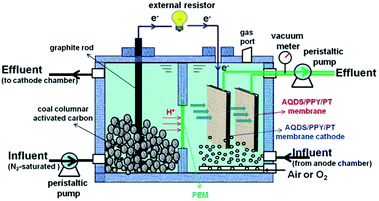
The dual-chamber MFC reactor was made of non-conductive plexiglas plate enclosing two chambers of dimensions 7 cm × 8 cm × 11 cm (total volume of 616 cm3 for each). The rectangular cathode and anodic chamber were separated by proton exchange membrane (PEM, Nafion 117, Dupont Co., USA) with the effective size of 4 cm × 4 cm. The anode chamber with the cumulated volume of 316 cm3 was packed with granular graphite (4 mm in diameter, 8 mm in average length) for microbial colonization. For better electron collection and conduction, two graphite rods (10 mm in diameter and 15 cm in length) were inserted in the anode chamber to conduct electrons. During the startup period, anaerobic sludge collected from Lingshui municipal wastewater treatment plant in Dalian city was used as the inoculums to cultivate and accumulate the electrochemically active microorganisms in the anode chamber. In the cathode chamber, 50 mM K3[Fe(CN)6] in 20 mM phosphate buffer solution (PBS, pH = 7) was used as electron accepter. Two graphite rods (10 mm in diameter and 15 cm in length) were used as the cathode electrodes. The external resistance of MFC was fixed at 1000 Ω in the startup period.After successful start up that is characterized by maintaining the maximum cell voltage at a stable value during consecutive cycle, the MFC was transformed into the MFC–MBR coupled system as illustrated in Fig. 1. Synthetic wastewater containing 0.8 g L−1 glucose (800 mg L−1 COD), 0.13 g L−1 KCl, 0.38 g L−1 NH4Cl (100 mg L−1 NH4+–N), 0.24 g L−1 NaHCO3 and 0.033 g L−1 NaH2PO4 was continuously fed into the anodic chamber through a peristaltic pump. The effluent of anodic chamber was directly run into the cathode chamber, in which the aerobic active sludge had a mixed liquor suspended solid (MLSS) concentration of 4.513 g L−1. The two graphite rods were taken out and two AQDS/PPY/PT membrane modules (8 cm × 8 cm) with active membrane size of 4 cm × 4 cm (active area: 32 cm2) were placed in the cathode chamber, one was used as both the test membrane (TM) and the cathode that is connected with the anode through external circuit, and another was used as the control membrane (CM) without connected with the anode. Thus the two membrane modules were placed around the same hydrodynamic and sludge circumstances. Membrane effluent of the two membrane modules were invariably drew out by a peristaltic pump with two pump heads to ensure the same fluxes. The net effective volumes of anodic and cathode chamber were 300 cm3 and 424 cm3 respectively. Air at the flow rate of 2.5 L h−1 was pumped continuously into the cathode chamber beneath the two membrane modules by two aerators to maintain the dissolved oxygen (DO) concentration at ca. 5.0–5.5 mg L−1.
Membrane cleaning was conducted by physical cleaning when the transmembrane pressures (TMP) reached at 0.03 MPa. The membrane modules were washed and back-flushed sufficiently with tap water (with pressure). One operation cycle refers to the time range from the cleaned membrane modules put in the cathode chamber to the next membrane cleaning.
The operation period including four stages was selected to investigate the membrane fouling under different operational conditions. In the Stage 1 and 2, the influent peristaltic pump was set to a speed of 1.2 rpm with 3 L day−1, the external resistance was 1000 Ω, the hydraulic retention time (HRT) of the anodic and cathode chamber were 2.4 h and 3.39 h, respectively, and the total HRT was 5.79 h. In the Stage 3 and 4, the speed of influent pump was set to 0.6 rpm, but the external resistance was selected as 1000 Ω in the former case and 500 Ω in the latter case, the HRT of the anodic and cathode chamber were 4.8 h and 6.78 h, respectively, and the total HRT was 11.58 h.
The voltage generated was recorded directly every 30 min using a 32-channel data acquisition system (PISO-813, ICP-DAS Co., Ltd) connected to a personal computer via a PCI interface. The electrode potential was measured every day using a multimeter (UT803, China). Saturated calomel electrode (SCE) was immersed into the cathode chamber as the reference electrode for cathode potential measurement.
2.3 Analytical methods
The membrane pore diameter was measured by the bubble point method (China national standard, GB/T 24219-2009).28 The dynamic contact angle was measured by a dynamic contact angle analyzer (DCA-322, America). The pure water flux of the membrane module was determined using tap water with 106 cm water head drop and the TMP was determined as 10.388 kPa. Bull serum albumin (BSA) was used as the model protein to evaluate the protein adsorption performance of PT and AQDS/PPY/PT. Briefly, the membranes with size of 5 cm × 1 cm were submerged in 10 mL BSA solution (1.0 g L−1, 0.2 M PBS at pH = 7.5). Then, the mixture was placed in a table concentrator with a speed of 150 rpm at 30 °C for 24 h to reach the adsorption equilibrium. The concentrations of BSA before and after adsorption were measured by the ultraviolet spectroscopy method at 280 nm.The COD, ammonium nitrogen (NH4+–N), nitrite nitrogen (NO2−–N), nitrate nitrogen (NO3−–N), mixed liquor suspended solids (MLSS) and mixed liquor volatile suspended solids (MLVSS) were analyzed by the APHA standard methods.29 Hydrogen peroxide (H2O2) was determined spectrophotometrically using titanium(IV) oxysulphonate–sulfuric acid complex (TiOSO4·xH2SO4·xH2O).30 The extracellular polymeric substances (EPS) was extracted and determined by the modified heating method,31 which was calculate as the sum of loosely bound EPS and tightly bound EPS.
The surface morphology of membrane was obtained by JSM-5600LV scanning electron microscopy (SEM), X-ray photoelectron spectroscopy (XPS) analysis was performed on an ESCALAB MK II X-ray photoelectron spectrometer.
The TMP was measured by two vacuum meters to monitor membrane fouling. Cell voltage was recorded by a data acquisition system connected to a personal computer. Polarization and power density curves were obtained using a potentiostat/galvanostat model 263A at a scan rate of 1 mV s−1. The current density was normalized to the net volume (316 cm3) of anode chamber. Coulombic efficiency (CE) was calculated as follow:
 | (1) |
Filtration resistance was also used in this work to evaluate membrane fouling. The total filtration resistance contains the membrane resistance, the pore blocking resistance and the cake layer resistance. Herein, the cake layer resistance and the pore blocking resistance can also be called reversible resistance and irreversible resistance, respectively. The filtration resistances can be expressed by the Darcy formula:32
 | (2) |
3. Results and discussion
3.1 Properties of the modified membrane
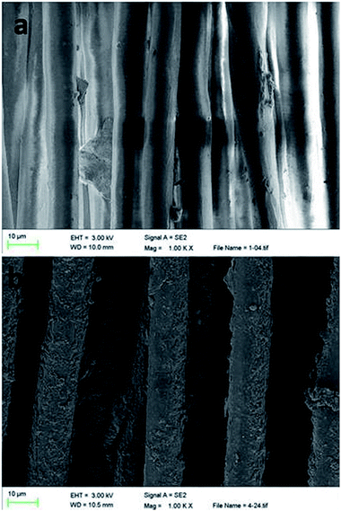
The membrane morphology is shown Fig. 2. The original PT fiber exhibits very smooth surface. After the chemical oxidative polymerization reaction, a rough surface composed of a large number of polymer particles was observed on the AQDS/PPY/PT membrane. It seemed that these polymer particles were tightly attached on the fiber surface forming an apparent layer structure.Fig. 3 shows the XPS spectra of AQDS/PPY/PT. It is no surprise that the C, O, S, and N elements are presented in the full-scan XPS pattern. To further confirm the chemical states of the abovementioned elements, the core level XPS spectra of C 1s, N 1s and S 2p were investigated. The high-resolution C 1s peak can be divided into four components at 284.1, 284.7, 285.7 and 287.7 eV, which are assigned to C–C, C–H, C–N and C![[double bond, length as m-dash]](https://www.rsc.org/images/entities/char_e001.gif) O groups in AQDS/PPY composite. The high-resolution N 1s spectrum are composed of two peaks at 399.8 and 401.5 eV, attributing to the functional groups of –NH– (pyrrolic N) and –N+-in PPY. Two components located around 167.2 and 168.1 eV are observed in the XPS pattern of S 2p region for the S 2p3/2 and S 2p1/2 transitions, which is indicative of the existence of S4+ (SO32−) species in AQDS, agreeing well with the previous reports.33,34 Above results confirmed the successful synthesis of AQDS/PPY composites on the PT membrane surface. Moreover, it is worth noting that the Fe element also presents in the full-scan XPS pattern. The high-resolution XPS spectra of Fe 2p region consists of three photoelectron peaks at 724.4 eV for Fe 2p1/2, 711.3 eV for Fe 2p3/2 and 719.8 eV for a shakeup satellite.34 The Fe 2p3/2 peak can be deconvoluted into two components with peak position around 712.0 and 710.2 eV, which correspond to Fe3+ and Fe2+, respectively.35 The major component is found to be Fe2+, indicating that a large amount of the Fe3+ was reduced into Fe2+ during the chemical oxidative polymerization of pyrrole monomer.
O groups in AQDS/PPY composite. The high-resolution N 1s spectrum are composed of two peaks at 399.8 and 401.5 eV, attributing to the functional groups of –NH– (pyrrolic N) and –N+-in PPY. Two components located around 167.2 and 168.1 eV are observed in the XPS pattern of S 2p region for the S 2p3/2 and S 2p1/2 transitions, which is indicative of the existence of S4+ (SO32−) species in AQDS, agreeing well with the previous reports.33,34 Above results confirmed the successful synthesis of AQDS/PPY composites on the PT membrane surface. Moreover, it is worth noting that the Fe element also presents in the full-scan XPS pattern. The high-resolution XPS spectra of Fe 2p region consists of three photoelectron peaks at 724.4 eV for Fe 2p1/2, 711.3 eV for Fe 2p3/2 and 719.8 eV for a shakeup satellite.34 The Fe 2p3/2 peak can be deconvoluted into two components with peak position around 712.0 and 710.2 eV, which correspond to Fe3+ and Fe2+, respectively.35 The major component is found to be Fe2+, indicating that a large amount of the Fe3+ was reduced into Fe2+ during the chemical oxidative polymerization of pyrrole monomer.
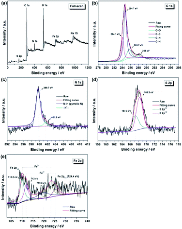 | ||
| Fig. 3 (a) Wide-scan XPS spectrum of the AQDS/PPY/PT membrane, and the high resolution core-level XPS spectra of (b) C 1s, (c) N 1s, (d) S 2p and (e) Fe 2p. | ||
The physicochemical parameters such as weight, resistance, pore size, dynamic contact angle, water flux and BSA adsorption of the original and the modified membranes are shown in Table 1. In this work, the oxidative polymerization of pyrrole monomer took place mainly on membrane surface. Of necessity, on the other hand, this process would also proceed inside the membrane fiber pore. As a result, the original PT fibers were coarsened after modified by the AQDS/PPY composites, as displayed in Fig. 2. Moreover, the weight and pore size of AQDS/PPY/PT membrane is increased by ca. 20% and decreased by ca.55.4%, respectively, compared to the fresh PT membrane. In comparison to the insulating PT membrane, the resistance of the AQDS/PPY/PT membrane is obviously decreased to 430 Ω cm−1 due to the excellent conductivity of PPY. Although its resistance is much higher than other conducting carbon materials, the AQDS/PPY/PT membrane is still a candidate as an electric conductive membrane for application in the MFC–MBR coupled system. Moreover, the dynamic contact angle also decreased sharply from 52.2° for the blank PT membrane to 5.1° for the AQDS/PPY/PT membrane, indicating the dramatic increase in membrane hydrophilicity, which results from the favourable hydrophilic functional groups in PPY matrix and its anionic dopant of AQDS. In comparison to the blank PT membrane, the water flux of the AQDS/PPY/PT membrane decreased only about 9.2% achieving at 9187.5 L h−1 m−2, which is attributed to the covered and/or narrowed pores size. Anyway, this slight decline in water flux should benefit from the increased hydrophilicity and the decreased contact angle of the modified membrane. Protein adsorption is one of the most important indicators to evaluate the anti-fouling property of membrane. The amount of BSA adsorbed on the blank PT and the AQDS/PPY/PT membranes is 740 and 52 mg m−2, respectively, suggesting that the anti-fouling property of the AQDS/PPY/PT membrane is remarkably enhanced. This result is consistent with the previous widely accepted viewpoint that the hydrophilic groups on the membrane will absorb water molecules forming a hydrated layer, resulting in an obviously decrease in protein adsorption due to the occurrence of the stereo-hindrance effect on membrane surface.32
| Membrane | Weight increase (%) | Resistance (Ω cm−1) | Pore size (μm) | Dynamic contact angle (°) | Water flux (L h−1 m−2) | BSA adsorption (mg m−2) |
|---|---|---|---|---|---|---|
| PT | 0 | ∞ | 22 | 52.2 | 10117.5 | 740 |
| AQDS/PPY/PT | 19.7 | 430 | 9.8 | 5.1 | 9187.5 | 52 |
3.2 Performance of the MFC–MBR coupled system
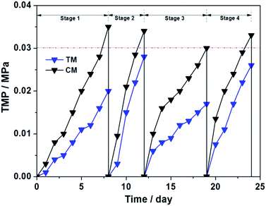
Generally, the membrane fouling is considered including three stages: (i) an initial short-term rapid rise in TMP; (ii) a long-term slow rise in TMP and (iii) a sharp increase in dTMP/dT, which is also known as TMP jump.36,37 Pollice et al. reported that the TMP jump was observed more frequently in the litre-level small-scale experiments.38In present work, the total volume of the reactor was only 1.2 L, which accords with the so-called “small-scale” standard. The TMP changes of TM and CM during the four operation cycles are shown in Fig. 4. As seen, the membrane fouling rate of TM during four operation cycles is 2.22, 5.6, 2.13 and 4.33 kPa day−1, respectively, which are apparent lower than that of CM (3.89, 6.8, 3.75 and 5.5 kPa day−1, respectively). These rapidly increased TMPs indicated that the membrane fouling stays at the TMP jump stage, which is mainly attributed to the small-scale reactor, lower HRTs, high organic loading rates and the consecutive membrane effluent in each operation period.25,26
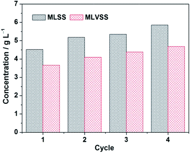
Moreover, no sludge was discharged during the whole operation period, implying the long sludge retention time (SRT). As seen in Fig. 5, the MLSS is gradually increased from Stage 1 to Stage 4 and the MLVSS/MLSS ratio is approximately maintained at ca. 0.8. It has been reported that a shorter SRT promotes more EPS production per unit biomass (a higher EPS concentration), leading therefore to a high membrane fouling rate.39 However, a too long SRT was also found causing the excessive membrane fouling due to the presence of a large amount of foulants and the high sludge viscosity,40 although both EPS and SMP (soluble microbial product) contents decrease under the prolonged SRT operation. Obviously, in current SRT terms, the membrane fouling rate of TM in the MFC–MBR coupled system is significantly reduced in each test stage compared to the rapid growth in TMP of CM. Taking into account that the TM and CM were placed synchronously into the cathode chamber of MFC, thus the two membrane modules are in the same water phase environment and conditions, except for whether or not connected with anode through external resistance. Based on this, it can be deduced that the internal electric field of MFC leads to an apparent membrane fouling reduction of TM in the MFC–MBR coupled system.
The evolution of cell voltage and anode potential during the four stages operation are depicted in Fig. 6. The anode potential is relatively stable and basically maintained in the range of −380 ∼ −420 mV vs. SCE in the whole operation period, whereas the cell voltage decreased gradually in each operational stage due to the inhibition effect of the formed filter cake on ORR through blocking H+ and dissolved oxygen molecules transport to AQDS/PPY/PT membranes surface. After cathode membrane cleaning, the cell voltage reached the highest value of each stage. Obviously, the cell voltage in this study is much smaller than that obtained in the normal MFC, which can be ascribed to the negative V-onset of ORR over AQDS/PPY composites as our previous work reported.30 On the other hand, although the operation condition and external resistance are the same for Stage 1 and 2, the cell voltage decline rate and membrane fouling rate of the latter are both higher than those of the former, which could because of the accumulation of irreversible membrane fouling, higher sludge viscosity and larger amounts of foulants after Stage 1 operation. This observation indicates that a low cell voltage would also associate with the rapid membrane fouling in the MFC–MBR coupled system. Under the condition of the doubled HRT in Stage 3, more COD was removed in anodic chamber of MFC and thus producing more electrons, as s result, the power output was enhanced and became more stable. In the Stage 4, the halved external resistance caused a decrease in the cell voltage.
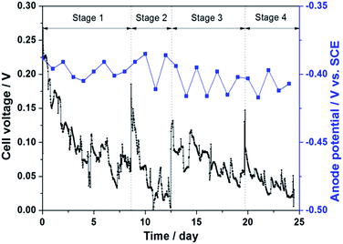 | ||
| Fig. 6 Voltage output and anode potential changes of the MFC–MBR coupled system during the four stage operation. | ||
Fig. 7 shows the effluent qualities of anode chamber of MFC and the two membrane modules (CM and TM). As seen, the H2O2 concentration and pH of TM effluent were all higher than those of CM, whereas no notable difference was observed in the concentrations of NH4+–N, NO2−–N and NO3−–N in TM and CM effluents. It is well known that AQDS is a high-active catalyst and enable catalyzing the 2e− ORR to produce H2O2 in situ.30,41
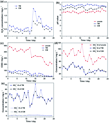 | ||
| Fig. 7 The influent and effluent properties of the MFC–MBR coupled system and the pure MBR during the four stage operation. | ||
On the TM surface, the PPY-bound AQDS molecules can efficiently catalytic reduce the dissolved oxygen to generate H2O2 under the action of internal electrical field of MFC, meanwhile, the ORR consumes H+ resulting in an increased pH value in cathode chamber. Certainly, partial H2O2 generated on TM would diffused into the bulk solution, thus a small quantity of dilute H2O2 was also detected in CM effluent. The H2O2 concentration of TM effluent decreased in gradually each operational stage and its change tendency followed that of cell voltage. In Stage 1 and 2, the H2O2 concentration was ca. 0.6 mg L−1, while it increased obviously reaching the highest point of ca. 2.1 mg L−1 in Stage 3, which is mostly due to the fact that the prolonged HRT not only results in a higher COD removal rate, but also produces more electrons in anode chamber. Thus, more H2O2 was generated and accumulated on TM. In Stage 4, the amount of H2O2 decreased gradually but was still higher than that in Stage 1 and 2.
The COD removal rate of anode chamber in Stage 1 and 2 was ca. 44%, and its value increased to about 60% in Stage 3 and about 74% in Stage 4 as the HRT was doubled. During the long-term operation, the dissolved oxygen molecules in cathode chamber could permeate through PEM into anode chamber and promote the growth of aerobic or facultative microorganisms,13,39 resulting in the continue decrease of COD in anode effluent in Stage 3 and 4. Overall, the MFC–MBR coupled system exhibits admirable performance for COD removal according to the COD change between the influent and the membrane effluent. The COD removal rate was maintained at ca. 90% in Stage 1 and 2, then increased gradually in Stage 3 and finally achieved at 100% in Stage 4. The average CE of the MFC–MBR coupled system during the four stages operation were 1.58%, 0.77%, 1.53%, and 1.57%, respectively, which are much lower than the normal MFC. This could be due to the short HRT and the high resistance of the AQDS/PPY/PT membrane, which hinders the electricity production performance and the rapid electron-transport.
Even so, the abovementioned findings indicate that under the conditions of the external resistance at 1000 Ω and the total HRT at 11.58 h, the MFC–MBR coupled system exhibited the best anti-membrane fouling performance and generated high-quality effluent. Therefore, the operation parameters of Stage 3 were adopted in the long-term operation experiment to evaluate membrane anti-fouling performance and clarify the anti-fouling mechanism of AQDS/PPY/PT membrane.
3.3 The anti-fouling performance and mechanism of AQDS/PPY/PT membrane
Fig. 8 shows the TMP changes of TM and CM during the long-term operation under the optimum conditions. The membrane fouling of the two membrane modules were almost similar to that in Stage 3 in Fig. 4. In comparison with CM under the same membrane flux, TM shows a longer operation period and a lower membrane cleaning frequency due to the favorable membrane fouling reduction during the 23 days operation. Polarization curve, power density, membrane resistances and the filter cake parameters of the CM and TM were comprehensively investigated and the membrane resistances are summarized in Table 2.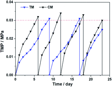 | ||
| Fig. 8 TMP changes of TM and CM under the optimum condition of external resistance at 1000 Ω and total HRT at 11.58 h. | ||
| Rm (109 m−1) | Rf (1011 m−1) | Rc (1012 m−1) | Rt (1012 m−1) | |
|---|---|---|---|---|
| TM | 4.07 | 3.1 | 7.96 | 8.28 |
| CM | 5.86 | 8.13 | 8.73 |
As seen, both the two membrane modules exhibited very small Rm due to big pore size and good hydrophilicity of the AQDS/PPY/PT membrane.
Rc was the main contributor towards total resistance, which were 96.14% and 93.13% of Rt for TM and CM, respectively. The irreversible resistance, Rf, was accounted respectively for 3.74% and 6.71% of Rt for TM and CM. Although the contribution of Rf to Rt is insignificant compared to that of Rc, it could cause a significant decline in permeation fluxes with time and thereby was of great importance for the continuous long-term operation of MBR.2 The lower Rf value of TM, which was 55.6% of CM, indicates that the irreversible resistance could be effectively controlled on TM, which could be more beneficial for the long-term operation of the MFC–MBR coupled system.
During the long-term operation, the polarization curve and power density of the fresh, fouled and cleaned AQDS/PPY/PT membranes in the MFC–MBR coupled system were also measured. As seen from Fig. 9, no significant polarization loss or mass transfer loss was observed in the MFC–MBR coupled system operating with these different membranes. Compared to the fresh AQDS/PPY/PT membrane, apparent declines in the open circuit voltage (OCP) and the maximum power density (MPD) were found for the fouled membrane. Although the OCP and MPD of the fouled membrane increased to a certain extent after the membrane cleaning, its performance could not be thoroughly recovered as that of the fresh one, resulting in a noticeable and irreversible influence on the electricity generation performances of the MFC–MBR coupled system during the long-term operation with the fouled AQDS/PPY/PT membrane. On the other hand, it should be noted that even for the fresh AQDS/PPY/PT membrane, the OCP and MPD values were merely 0.39 V and 0.29 W m−3, respectively, indicating a low power output and a poor electricity generation performance of the MFC–MBR coupled system. Thus, it is necessary to replace PT substrate membrane with other better conducting matrix membrane materials to drastically improve the electricity production capacity of the MFC–MBR coupled system.
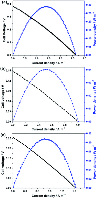 | ||
| Fig. 9 The polarization and power density curves of the MFC–MBR coupled system operating with different AQDS/PPY/PT membranes: (a) fresh, (b) fouled and (c) cleaned. | ||
On day 23 in Fig. 8, the filter cake on the AQDS/PPY/PT membrane surface was diluted with DI water into 200 mL, and the parameters such as MLSS, MLVSS and EPS were measured to analyse the difference between TM and CM, and the results were summarized in Table 3. As seen, the MLSS, MLVSS, EPS and EPS/MLVSS ratio of TM were reduced respectively by 19.14%, 21%, 29.34% and 10.5% when compared with that of CM, indicating that less EPS was adsorbed on TM surface and both the reversible fouling and the irreversible fouling derived respectively from the filter cake layer and the gel layer were reduced notably.
Based on the above results, the anti-fouling mechanism of AQDS/PPY/PT membrane in the MFC–MBR coupled system was proposed and illustrated in Fig. 10. For the submerged MBR, three types of foulants such as EPS colloid, SMP and sludge particles are generally involved in the membrane fouling process.2,32 The bioelectrochemical reactions occurred in the anode chamber producing electrons during microbial metabolism, and then the collected electrons in the anode pass through an external load and arrive at the cathode chamber.24 On the one hand, the combined actions of the electric field force and the Coulomb force will significantly enhance the back-diffusion of the negative charged EPS colloid and sludge particles away AQDS/PPY/PT membrane, and simultaneously inhibit the compression of filter cake layer and decrease the proportion of EPS in the filter cake, which are very beneficial to membrane fouling reduction.19,20 On the other hand, the following electrochemical and chemical reactions would happen on the AQDS/PPY/PT membrane:
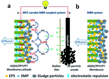 | ||
| Fig. 10 Schematic diagram of (a) the anti-fouling mechanism of TM and (b) the fouling processes of CM. | ||
(i) the reduction of PPY-bound AQ molecules forming H2AQ using the self-produced electrons and protons of MFC via eqn (3);
| AQ + 2H+ + 2e− → H2AQ | (3) |
(ii) ORR catalyzed by the electrogenerated H2AQ forming H2O2 according to eqn (4);
| H2AQ + O2 → AQ + H2O2 | (4) |
(iii) the reduction of Fe3+ that was incorporated in AQDS/PPY composites forming Fe2+ through the internal electric field of MFC according to eqn (5):
| Fe3+ + e− → Fe2+ | (5) |
(iv) the generation of ˙OH radicals through the well-known Fenton reaction according to eqn (6):
| Fe2+ + H2O2 → Fe3+ + ˙OH + OH− | (6) |
Herein, the formed Fe3+ in eqn (6) can be rapidly reduced to regenerate Fe2+ through eqn (5) achieving Fe3+/Fe2+ cycling and thereby establishing a self-sustainable heterogeneous electro-Fenton process. The produced H2O2 and ˙OH radicals on the AQDS/PPY/PT membrane surface and inside the membrane pore can be viewed as the in situ oxidant for membrane chemical cleaning, which can oxidize the organic compounds into more hydrophilic intermediate residuals.20,24 Moreover, the organic matter containing carboxyl, ketonic and aldehyde functional groups are more susceptible to hydrolysis at high pH medium.2 In this context, the membrane fouling mitigation was greatly enhanced on TM when compared to CM, since the higher H2O2 concentration and pH value were more suitable for membrane fouling reduction.
3.4 Characterization of the used AQDS/PPY composite layer
The stability of AQDS/PPY composite modified PT fibre membrane was investigated by using SEM, XPS and contact angle after 25 running days in the module.The SEM images of the inner side and the outer side of TM and CM are shown in Fig. 11. As seen, the outsides of TM and CM were both accumulated with pollutant even after physical cleaning, and TM performed better than CM in term of the anti-fouling property with less pollutant at the surface and between the fibers. Additionally, compared to the SEM images in Fig. 2b, no apparent detachment of the AQDS/PPY composite layer was found, indicating the good stability of TM.
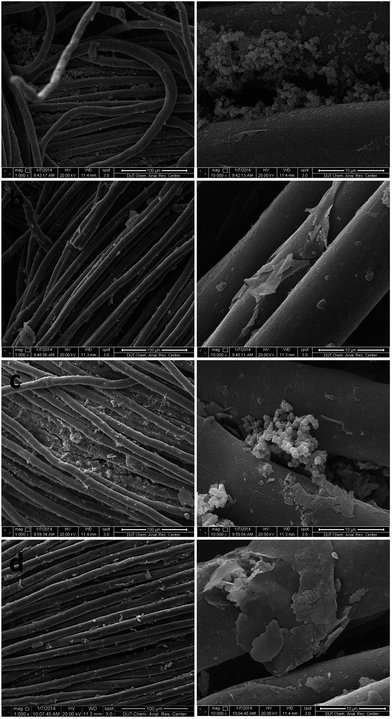 | ||
| Fig. 11 SEM images of outer side (a, c) and inner side (b, d) of TM and CM, respectively, after 25 running days in the module. | ||
The contact angles of TM and CM were 4.2 and 3.8, which shows better hydrophily due to the pollutant on the surface and inside of the membrane containing inorganic salt and organic matters with hydrophilic functional groups.
Fig. 12 shows the core level XPS spectra of Fe 2p and S 2p of AQDS/PPY/PT membrane after 25 running days in the module. Compared to Fig. 3d and e, the high-resolution Fe 2p region also contains of three peaks at 722.6 eV for Fe(III) 2p1/2, 712.5 eV for Fe(III) 2p3/2 and 709.3 eV for Fe(II) 2p3/2, while the S 2p region presents a main photoelectron peak at ca. 180 eV. These results clearly indicate that AQDS/PPY composites layer is still existence on the PT membrane surface after long-term operation and physical cleaning.
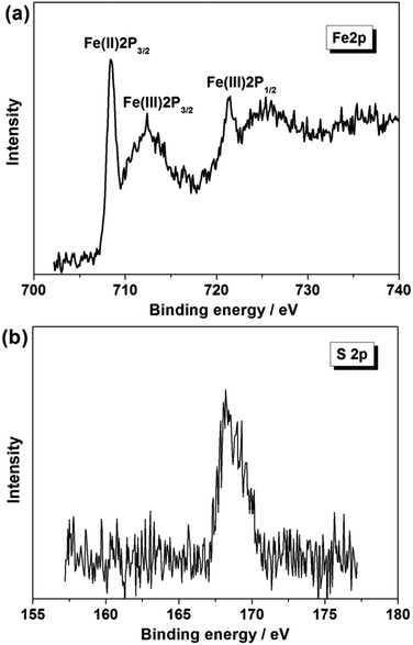 | ||
| Fig. 12 The high resolution core-level XPS spectra of (a) Fe 2p and (b) S 2p of the AQDS/PPY/PT membrane after 25 running days in the module. | ||
3.5 Outlook
Table 4 summarized the comparisons of the comprehensive performance in membrane fouling mitigation between bioelectrochemical membrane reactor (BEMR), membrane bio-electrochemical reactor (MBER), electrochemical membrane bioreactor (EMBR) as well as membrane electro-bioreactor (MEBR) reported in the literature and the MFC–MBR coupled system studied in this work. Undoubtedly, the MFC–MBR coupled system developed in this study integrated the advantages of both MBR for COD removal and MFC for energy recovery, which has demonstrated the capacity to generate high-quality effluent and to promote membrane anti-fouling property.| System | Membrane material | Membrane function | Coulombic efficiency | Approach to membrane fouling mitigation | Ref. |
|---|---|---|---|---|---|
| MBR | PPY/PT | Cathode and filter membrane | — | Electrostatic repulsion | 19 |
| BEMR | PPY/PT | Cathode and filter membrane | — | Flocculation/coagulation electrostatic repulsion | 20 |
| EMBR | Stainless steel mesh | Cathode and filter membrane | 4.5% | Electrostatic repulsion in situ generated H2O2 | 21 |
| EMBR | Conductive UF membrane | Cathode and filter | 8.5 ± 4.5% | No significant membrane fouling occurred | 22 |
| Single-chamber MFC–MBR | Non-woven cloth | Separator and filter membrane | 36% | No significant membrane fouling occurred | 23 |
| MBER | Hollow-fiber ultrafiltration membrane | Filter membrane | 30–36% | Without considering membrane fouling migration | 25 |
| MBER | Hollow-fiber ultrafiltration membrane | Filter membrane | 10–30% | Lower organic concentration in cathode chamber | 26 |
| AnMBER | Hollow-fiber microfiltration membrane | Filter membrane | 10.3 ± 1.8% | Improving the mixed liquor properties | 27 |
| Dual-chamber MFC–MBR | AQDS/PPY/PT | Cathode and filter membrane | 4.58% | Electrostatic repulsion in situ electro-Fenton | Present work |
The electrostatic repulsion and the self-sustainable heterogeneous electro-Fenton oxidation process originated from the internal electric field of MFC greatly developed and enriched the anti-membrane fouling principle and mechanism of microorganism, electrochemistry and membrane separation hybrid or integrated/coupled systems. Nevertheless, the electricity generation capacity and energy recovery efficiency of the present MFC–MBR coupled system are still limited. To make this novel system more effective and applicable, more studies are required to optimize the catalytic cathode membrane materials (for example, the metal oxide/carbon membrane materials) to (i) achieve continuous high power output, (ii) establish the more efficient self-sustainable electrochemical advanced oxidation process or MFC-driven bio-electrochemical advanced oxidation process for oxidizing/degrading the recalcitrant organic pollutants into the biodegradable intermediates to gain more high-quality effluent that is safer and less toxic to ecosystem or human health, and (iii) further elucidate the MFC-driven membrane anti-fouling performance and mechanism.
4. Conclusions
The chemical oxidative polymerization-doping process has been proven to be a good strategy to prepare the AQDS/PPY/PT membrane with favorable electrical conductivity and hydrophilicity. Using the AQDS/PPY/PT membrane as filtration material and cathode simultaneously, the MFC–MBR coupled system has demonstrated the capability to harvest electricity from wastewater, generate high-quality effluent and reduce membrane fouling. The membrane anti-fouling performance was attributed mainly to that, on the one hand, the self-generated electric field from MFC promotes the back-diffusion of the foulants away from the membrane surface through the electrostatic repulsion, on the other hand, enables the PPY-bound AQDS efficient catalyzing ORR to form H2O2 and even the ˙OH radicals on membrane surface and inside the membrane pore via the in situ self-sustainable heterogeneous electro-Fenton process. Although the electricity generation capacity was still limited in present work, the MFC–MBR coupled system mitigated membrane fouling effectively. Greater efforts are being carried out in our future work to further enhance the electricity generation capacity and membrane anti-fouling property utilizing the excellent conductive and catalytic metal oxide/carbon composite membrane material.Acknowledgements
The authors acknowledge the financial support from the National Natural Science Foundation of China (no. 21177017, 21437001).Notes and references
- F. Fan and H. Zhou, Environ. Sci. Technol., 2007, 41, 2523–2528 CrossRef CAS
.
- F. Meng, S.-R. Chae, A. Drews, M. Kraume, H.-S. Shi and F. Yang, Water Res., 2009, 43, 1489–1512 CrossRef CAS PubMed
.
- A. Ding, F. Qu, H. Liang, J. Ma, Z. Han, H. Yu, S. Guo and G. Li, Chem. Eng. J., 2013, 223, 908–914 CrossRef CAS PubMed
.
- G. Sabia, M. Ferraris and A. Spagni, Chem. Eng. J., 2013, 221, 176–184 CrossRef CAS PubMed
.
- K. Kimura, I. Tanaka, S.-I. Nishimura, R. Miyoshi, T. Miyoshi and Y. Watanabe, Water Res., 2012, 46, 5725–5734 CrossRef CAS PubMed
.
- J. Lee, W.-Y. Ahn and C.-H. Lee, Water Res., 2001, 35, 2435–2445 CrossRef CAS
.
- C. M. Pang, P. Hong, H. Guo and W.-T. Liu, Environ. Sci. Technol., 2005, 39, 7541–7550 CrossRef CAS
.
- S. Wang, G. Guillen and E. M. Hoek, Environ. Sci. Technol., 2005, 39, 6461–6469 CrossRef CAS
.
- A. Ramesh, D. Lee and J. Lai, Appl. Microbiol. Biotechnol., 2007, 74, 699–707 CrossRef CAS PubMed
.
- L. Liu, D. Y. W. Di, H. Park, M. Son, H.-G. Hura and H. Choi, RSC Adv., 2015, 5, 7340–7348 RSC
.
- C. Zhao, X. Xu, J. Chen, G. Wang and F. Yang, Desalination, 2014, 340, 59–66 CrossRef CAS PubMed
.
- R. S. Trussell, R. P. Merlo, S. W. Hermanowicz and D. Jenkins, Water Res., 2007, 41, 947–958 CrossRef CAS PubMed
.
- H. Ng, T. Tan, S. Ong, C. Toh and Z. Loo, Water Sci. Technol., 2006, 53, 7–13 CrossRef CAS
.
- X. Su, Y. Tian, Z. Sun, Y. Lu and Z. Li, Biosens. Bioelectron., 2013, 49, 92–98 CrossRef CAS PubMed
.
- Z. Ying and G. Ping, Sep. Purif. Technol., 2006, 52, 154–160 CrossRef CAS PubMed
.
- P. Wang, J. Ma, Z. Wang, F. Shi and Q. Liu, Langmuir, 2012, 28, 4776–4786 CrossRef CAS PubMed
.
- E.-S. Kim, Q. Yu and B. Deng, Appl. Surf. Sci., 2011, 257, 9863–9871 CrossRef CAS PubMed
.
- T. Wu, B. Zhou, T. Zhu, J. Shi, Z. Xu, C. Hua and J. Wang, RSC Adv., 2015, 5, 7880–7889 RSC
.
- L. Liu, J. Liu, G. Bo, F. Yang, J. Crittenden and Y. Chen, J. Membr. Sci., 2013, 429, 252–258 CrossRef CAS PubMed
.
- J. Liu, L. Liu, B. Gao and F. Yang, J. Membr. Sci., 2013, 430, 196–202 CrossRef CAS PubMed
.
- Y.-K. Wang, W.-W. Li, G.-P. Sheng, B.-J. Shi and H.-Q. Yu, Water Res., 2013, 47, 5794–5800 CrossRef CAS PubMed
.
- Y.-K. Wang, G.-P. Sheng, B.-J. Shi, W.-W. Li and H.-Q. Yu, Sci. Rep., 1864, 3 DOI:10.1038/srep01864
.
- L. Malaeb, K. P. Katuri, B. E. Logan, H. Maab, S. P. Nunes and P. E. Saikaly, Environ. Sci. Technol., 2013, 47, 11821–11828 CrossRef CAS PubMed
.
- Y.-K. Wang, G.-P. Sheng, W.-W. Li, Y.-X. Huang, Y.-Y. Yu, R. J. Zeng and H.-Q. Yu, Environ. Sci. Technol., 2011, 45, 9256–9261 CrossRef CAS PubMed
.
- Z. Ge, Q. Ping and Z. He, J. Chem. Technol. Biotechnol., 2013, 88, 1584–1590 CrossRef CAS
.
- J. Li, Z. Ge and Z. He, J. Chem. Technol. Biotechnol., 2014, 89, 1330–1336 CrossRef CAS
.
- Y. Tian, C. Ji, K. Wang and P. Le-Clech, J. Membr. Sci., 2014, 450, 242–248 CrossRef CAS PubMed
.
- G. Wu, Mater. Chem. Phys., 2004, 85, 81–87 CrossRef CAS PubMed
.
- A. D. Eaton, L. S. Clesceri and A. E. Greenberg, Washington, DC, 2005, pp. 20001–23710.
- G. Zhang, F. Yang, M. Gao, X. Fang and L. Liu, Electrochim. Acta, 2008, 53, 5155–5161 CrossRef CAS PubMed
.
- X. Li and S. Yang, Water Res., 2007, 41, 1022–1030 CrossRef CAS PubMed
.
- F. Meng, H. Zhang, Y. Li, X. Zhang and F. Yang, J. Membr. Sci., 2005, 262, 107–116 CrossRef CAS PubMed
.
- Y. Wu, L. Qin, G. Zhang, L. Chen, X. Guo and M. Liu, Ind. Eng. Chem. Res., 2013, 52, 16698–16708 CrossRef CAS
.
- L. Guo, F. Chen, X. n. Fan, W. Cai and J. Zhang, Appl. Catal., B, 2010, 96, 162–168 CrossRef CAS PubMed
.
- L. J. Xu and J. L. Wang, Appl. Catal., B, 2013, 142–143, 396–405 CrossRef CAS PubMed
.
- B. Cho and A. Fane, J. Membr. Sci., 2002, 209, 391–403 CrossRef CAS
.
- J. Zhang, H. C. Chua, J. Zhou and A. Fane, J. Membr. Sci., 2006, 284, 54–66 CrossRef CAS PubMed
.
- A. Pollice, A. Brookes, B. Jefferson and S. Judd, Desalination, 2005, 174, 221–230 CrossRef CAS PubMed
.
- H. Y. Ng, T. W. Tan and S. L. Ong, Environ. Sci. Technol., 2006, 40, 2706–2713 CrossRef CAS
.
- S.-S. Han, T.-H. Bae, G.-G. Jang and T.-M. Tak, Process Biochem., 2005, 40, 2393–2400 CrossRef CAS PubMed
.
- G. Zhang and F. Yang, Phys. Chem. Chem. Phys., 2011, 13, 3291–3302 RSC
.
| This journal is © The Royal Society of Chemistry 2015 |

