
Hybrid magnetic–plasmonic nanocomposite: embedding cobalt clusters in gold nanorods
A. N. Emamab,
M. B. Mohamed*cd,
E. Girgisae and
K. V. Raof
aAdvanced Materials & Nanotechnology Lab., Centre of Excellence for Advanced Sciences (CEAS), National Research Centre (NRC), Giza, Egypt
bBiomaterials Department, National Research Centre (NRC), Giza, Egypt
cNational Institute of Laser Enhanced Sciences (NILES), Cairo University, Giza, Egypt. E-mail: monabmohamed@gmail.com
dNanotech Egypt for Photo-electronics, Dream Land City, Giza, Egypt
eSolid State Physics Department, National Research Centre (NRC), Giza, Egypt
fDepartment of Materials Science, Royal Institute of Technology, Stockholm, S-100 44, Sweden
First published on 7th April 2015
Abstract
We developed a method to fabricate hybrid magnetic–plasmonic nanorods (Au–Co NRs) via a modified seed mediated method. The only modification is to use cobalt ions instead of Au3+ in the preparation of the seed solution to obtain gold nanorods doped with Co clusters. By adjusting the amount of cobalt seed solution, Au–Co NRs of controlled aspect ratio can be obtained. The optical properties of the obtained Au–Co NRs were investigated and compared to those of the pure Au NRs. A slight shift and broadening were observed in the alloys compared to the pure ones, which was attributed to the presence of Co clusters leading to suppression of the dielectric properties. High resolution transmission electron microscopy (HRTEM) images indicate the existence of Co clusters in situ in the Au NR host and clearly show the metal–metal interface. The magnetic properties of the obtained Au–Co NRs increase as the concentration of dopant Co cluster seeds increases, as investigated by vibrating sample magnetometry (VSM). Our approach allows us to design nanomaterials of controlled shape, optical and magnetic properties which have many promising applications in tharanostics and photoelectronics.
1. Introduction
Hybrid nanostructures containing both a magnetic phase and another functional phase have been attracting much interest from several researchers due to many important scientific and technological aspects.1 It is known that plasmonic nanostructures have unusual and pronounced optical properties, where the position of the localized surface plasmon resonance (LSPR) is strongly dependent on the particle shape, size, and chemical composition, as well as on the dielectric properties of the surrounding media.2–22 Thus, LSPR opened many opportunities to be used in a wide range of applications13,23 including chemical and biological sensing,24–27 probing,28 therapy and imaging.29–38Embedding magnetic clusters into plasmonic nanostructures (i.e. Au or Ag nanoparticles) would influence their magnetic and optical properties. In addition, these hybrid nanostructures have magneto-optical (MO) behaviour through the combination between ferromagnetic materials, and LSPR of the plasmonic nanoparticles. This is desirable for developing active nano-plasmonic devices such as magnetic field sensors and data storage.39
Their magnetic properties can be controlled via incorporation of ferromagnetic clusters within noble plasmonic nanostructure via chemical route.40–47 Wang et al. synthesized CoPt rod-like nanoalloy via ionic liquid method.48 Also, Cu–Pt nanorods of controlled aspect ratio had been prepared using a mixture of oleic acid and oleylamine.49
Several attempts had been carried out to prepare Au–Co hybrid nanostructure.50–64 Hall et al. focused on a template fabrication of Co–Au core–shell nanorods partially embedded in polycarbonate track-etch, and anodic aluminium oxide nano-porous membranes.58 Wetz et al.59 studied the parameters affecting the nucleation of Au nanoparticles (Au NPs) on the Co nanorods. Watts et al. determined the optimum conditions to grow gold on the surface of Co nanorods by galvanic displacement60 or by heterogeneous growth.59 Another structure of cobalt gold hybrid nanostructure was fabricated through formation of thin-film made of Au–Co–Au trilayers via several techniques such as lithography,50,65 ion beam etching,47 magnetron sputtering,61–64 and molecular beam epitaxy (MBE).64
In this work, we developed a convenient method to fabricate a rod-like Au–Co hybrid nanocomposite of controlled composition and aspect ratio via chemical routes based on seed mediated method.66,67
2. Experimental
2.1. Materials
Hydrogen tetrachloroaurate(III) trihydrate (HAuCl4·3H2O, Aldrich, 99.999%), cobalt acetate (Co(CH3COO)2, WINLAB, 98%), sodium borohydride (NaBH4, WINLAB, 98%), N-cetyl-N,N,N,-trimethyl-ammonium bromide (CTAB, Merck, 99%), silver nitrate (AgNO3, Sigma Aldrich, 99%), L-ascorbic acid (Vitamin C, Fluka, 99%) and purified water from the Millipore Milli-Q water purification system.2.2. Shape controlled synthesis of bimetallic Au–Co hybrid nanostructure
Colloidal Au–Co NRs has been prepared via seed-mediated method as described previously66,67 with little modification to introduce Co2+ ions in situ the lattice of the gold nanorods. Cobalt precursor was used instead of gold within the seed solution to induce the magnetic impurities as a dopant. In typical method; CTAB-stabilized seed solution of cobalt nanoclusters was prepared by reduction of 5.0 × 10⁻³ M Co(CH3COO)2 and 0.2 M CTAB with ice-cold aqueous 0.01 M NaBH4. 5 ml of an aqueous growth solution containing 0.2 M CTAB, 70 μl of 4 × 10⁻³ M AgNO3 and 1 × 10⁻³ M HAuCl4·3H2O in a test tube. Addition of the CTAB produced a colour change from yellow to brown-yellow suggesting the existence of ligand-substituted anions such as CTAB–Au3+ complex. Then 50 μl of 0.1 M L-ascorbic acid was added and followed by addition of specific volume of the seed solution. The colour of the solution gradually changed indicating the growth of the gold nanorods. The prepared particles have been separated from the growth solution to remove the excess CTAB by centrifugation at 10 °C.2.3. Characterization
UV-Visible absorption spectra for the prepared samples have been recorded using Ocean Optics USB 2000 spectrometer. The absorption was recorded within the appropriate scan range from 190 to 1100 nm. High Resolution Transmission Electron Microscope (HRTEM) model JEM-2100, equipped with scanning image observation device to give bright and dark-field STEM images at 200 kV, was used to investigate particle size, shape, and the chemical composition of the obtained samples. The unit comprises energy dispersive X-ray analyzer model JED-2300T. The XRD was recorded using Panalytical X'Pert Pro, Cu Kα radiation, λ = 1.546 Å) over a 2θ range of 4–80°. In addition, the exact content of Co2+ in situ the Au rods were performed using atomic absorption spectrometer (AAS) Varian Spectra AA 220/FS. Finally, the magnetic measurements were carried out using vibrating sample magnetometer (VSM), ADE Technologies, Inc. EV11 (Model 8810).3. Results and discussion
In order to investigate the influence of cobalt in situ gold nanostructure on the optical and magnetic properties, gold and Au–Co nanospheres were prepared. Spherical gold particles prepared by reducing gold ions using NaBH4 in presence of CTAB as a capping material. The same method used to prepare Au–Co spherical hybrid nanostructure, but instead of using gold ions, a mixture of gold and cobalt ions had been used. Fig. 1 represents the optical properties and the transmission electron microscopy (TEM) micrographs for the as-prepared particles from pure gold (Au), and gold–cobalt (Au–Co) nanoparticles (NPs). Based on the absorption spectra (Fig. 1a), it is clear that the spherical-like shape has been formed for each of pure Au gold particles (black line), and Au–Co nanoalloy (red line). The absorption spectra show only one absorption band, where the maximum wavelength (λmax) was about 523 nm owing to its surface plasmon resonance (SPR). The absorption spectrum of the Au–Co alloyed NPs shows a broader absorption red shifted than the plasmon band of the pure Au NPs, where (λmax) was about 530 nm, which is in agreement with the commonly observed in other Au bimetallic systems.68–71 | ||
| Fig. 1 (a) UV-Vis absorption spectrum, TEM images for both of (b) pure Au, and (c) hybrid Au–Co NPs. | ||
This was confirmed by imaging these particles using TEM as shown in Fig. 1b and c. It is clear that the obtained particles are uniform spherical nanoparticles. In case of Au NPs, the average size (D) was around 12 ± 1.5 nm with size distribution about ∼5.4% rms (Fig. 2b). The average size is about 15 ± 1.5 nm for cobalt doped gold NPs with size distribution about ∼6.7% rms (Fig. 1c). Slight red shift and broadening has been observed in absorption spectrum of Au–Co bimetallic NPs relative to the pure Au NPs. This might be due to the fact that the size distribution of pure Au NPs is narrower than that of the Au–Co NPs, and the aggregation of Au–Co NPs is more serious than the pure Au NPs. Also, the homogenous mixture of metal–metal bond between gold and cobalt leads to formation of an intermetallic or alloyed structure, where Co clusters diffuses into Au NPs host crystal.70,72 Templeton et al. reported that any change in the pure Au cores causes shift in the plasmon band.73 Thus, the electronic properties induced by the presence of cobalt clusters may also affect plasmon band position; as Au character increases and the Co becomes buried beneath the Au, these dielectric effects may be suppressed (Fig. 1a).74–76
 | ||
| Fig. 2 (a) TEM and (b) SAED micrographs of cobalt seeds. | ||
3.1. Rod-shaped Au–Co nanoalloy
Seed mediated method was used to prepare pure gold nanorods.66,67 In order to prepare Au–Co nanorods, the cobalt seed solution has been used instead of gold seed solution and added to the growth solution leads to formation of bimetallic gold–cobalt nanorods.Cobalt nanoclusters (seed solution) were prepared via chemical reduction of cobalt acetate in the presence of cationic surfactant (i.e. CTAB), which act as a capping material. NaBH4 has been used as a reducing agent. The role of acetate (i.e. CH3COO−) anion on formation of cobalt seed particles is to stabilize the cobalt nanoclusters similar to citrate (C3H5O(COO)33−) anion role in synthesis of metallic nanoparticles in combination with polymeric surfactant.77 Moreover, the presence of acetate anion may increase the rate of colloid formation due to its lower redox potential than other anion such as nitrate (NO3−), ascorbate, and bromide.78
Fig. 2 shows TEM and SAED micrographs of the prepared cobalt seed. It is clear that tinny spherical clusters are predominant of average size ∼5.2 ± 1.5 nm as shown in Fig. 2a. The crystallographic structure of individual cobalt clusters shows four reflection planes (400), (101), (110) and (311), which refer to the hexagonal structure of cobalt. The inter-planer distance was about 0.89, 1.92, 1.24, and 1.08 Å, respectively.
The formation of rod-shaped Au–Co hybrid nanostructure confirmed using absorption spectra and TEM images (see Fig. 3). It is well known that anisotropic rod-shaped plasmonic nanostructure is characterized by two modes of surface electrons oscillation, the first one is owing to the transverse surface plasmon resonance (T-SPR), and the other mode is owing to the longitudinal surface plasmon resonance (L-SPR).17 Fig. 3a shows the absorption spectra for pure Au (black line), and Au–Co NRs (red line). The aspect ratio (R) of the rod has been calculated from the absorption maximum of the L-SPR using the equation developed by Link et al.,79 where R was found to be 3.19 and 3.29 for both of Au–Co and Au NRs, respectively. It is clear that the absorption spectrum of rod shaped gold–cobalt hybrid nanostructure is slightly blue shifted than that of the pure gold nanorods. The T-SPR is blue shifted from 530 nm to 518 nm and the L-SPR band is blue shifted from 733 to 724 nm, for the case of pure gold nanorods and Au–Co hybrid NRs, respectively (Fig. 3a). It was reported that the plasmonic absorption depends on the ratio of the constituent materials.80 Blue shift in the plasmonic absorption of Co–Au nano-alloys has been reported by Xu et al.81 They attributed the blue shift of the plasmonic band to the change of the surface charge density and the mean free path of electron, due to the embedding of cobalt clusters in situ gold matrix. This leads to loss of the continuous density of states in the gold matrix.80–82 Fig. 3c and d show the high resolution TEM images of the pure gold nanorods and the hybrid Au–Co nanostructure which clearly show the embedding of cobalt clusters in situ the gold host.
 | ||
| Fig. 3 (a) UV-Vis absorption spectrum, TEM images for both of (b) Pure Au, and (d) Au–Co NRs, and HR-TEM lattice image for both of (c) Pure Au, and (e) Au–Co NRs. | ||
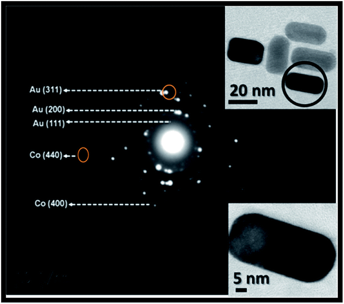
To investigate the crystal structure and confirm the formation of cobalt nanoclusters in situ Au–Co NRs, selected area electron diffraction (SAED) patterns, HRTEM and XRD were recorded and represented in Fig. 4–6, respectively. The SAED patterns show that, the diffraction spots are superimposed on the rings indicating the polycrystalline structure of the rod shape. In contrast, Au–Co hybrid nanorods were obtained by inserting cobalt clusters into gold nanorods. The d-spacing of adjunct fringes was found to be 0.126 nm, which is similar to the planar distance of Au[311] (0.123 nm) or Co[110] (0.125 nm). Also, the d-spacing of another adjunct fringes 0.21 nm and 0.089 nm, which similar to the planner distance of Au[200] or Co[400]. Therefore, it is important to understand the role of cobalt cluster in enhancing the growth of rod shape, and inducing the magnetic properties to the gold nanorods.
 | ||
| Fig. 4 SEAD patterns for prepared Au–Co NRs. | ||
 | ||
| Fig. 5 HRTEM micrograph for prepared gold nanorods doped with Co2+ ions at fixed concentration Co2+ ions of 1 × 10⁻³ M (i.e. 11.197 μg) (a), and 5 × 10⁻⁴ M (i.e. 5.598 μg) (b) in seed solution. | ||
 | ||
| Fig. 6 XRD Patterns for the prepared Au–Co nanorods (black) compared to the pure Au NRs (red). | ||
HR-TEM images in Fig. 5a shows breaking in the symmetry within the gold crystal lattice, due to the existence and diffusion of cobalt atoms through the gold lattice at the metal–metal interface. The lattice image at seed concentration of 1 × 10⁻³ M (i.e. 11.197 μg) shows d-spacing = 0.079 nm and 0.154 nm, which is similar to the planar distance of Au[511] (0.078 nm) or Co[102] (0.148 nm). While in case of using 5 × 10⁻⁴ M (i.e. 5.598 μg) of cobalt ions, the d-spacing is 0.145 nm and 0.173 nm is similar to the planer distance of Au[220] (0.144 nm) or Co[200] (0.178 nm) (Fig. 5b).
Four distinct features at 2θ = 38.2, 44.4, 64.6 and 77.6° have been observed in the XRD pattern of the Au NRs, which can be assigned to the strongest line reflections from (111), (200), (220) and (311) planes of the face-centered-cubic (fcc) of Au. In case of Au–Co NRs, three additional peaks appears at 2θ = 34.0, 41.8 and 51.03 which attributed to reflections from (211), (213) and (400) plans of hexagonal-closed-packed (hcp) of Co clusters embedded in the gold nanorods.
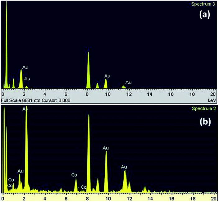
Energy dispersive X-ray (EDX) measurement is a powerful technique, which allows us to determine the exact ratio of elements in situ the samples during imaging of the rods. Fig. 7 represents the EDX data for each of Au and Au–Co NRs, It clear that the cobalt and gold content have an average of about 13.65, and 86.35 wt%, respectively. This is significant indication for the doping and diffusion of Co clusters in the gold nanorods matrix, and the formation of hybrid rod-shaped Au–Co nanostructure. Atomic absorption spectroscopy measurements were performed to ensure the presence of cobalt in the gold nanorod sample and to confirm EDX results. The exact Co2+ content in Au–Co NRs sample as measured by atomic absorption was about 3.762 μg, while the calculated content theoretical was 5.598 μg for 5 × 10⁻⁴ M of Co2+ ions seed solution.
 | ||
| Fig. 7 The EDX analysis for both of Pure Au NRs (a), and Au–Co NRs (b). | ||
The size and shape of Au–Co NPs could be tuned by changing the cobalt concentration in the seed solution (Fig. 8 and 9). The effect of the cobalt concentration on the growth of gold nanorods was monitored by measuring the absorption spectra and TEM images of the obtained Au–Co NRs prepared using different cobalt ions concentration (i.e. 111.92 to 5.598 μg).
 | ||
| Fig. 8 (I) Absorption spectra of the obtained gold nanorods using different molar concentration of Co2+ ions in the seed solution varied from 1.0 × 10⁻⁴ M to 0.01 M. (II) TEM images of the obtained Au–Co hybrid NRs at different Co3+ concentrations (a) 1.0 × 10⁻⁴ M, (b) 1.25 × 10⁻⁴ M, (c) 7.5 × 10⁻⁴ M, (d) 1.0 × 10⁻³ M & (e) 1.0 × 10⁻² M respectively. | ||
 | ||
| Fig. 9 Absorption spectra of prepared gold nanorods doped with Co2+ series with various aspect ratios using different amounts seed at fixed concentration Co2+ ions in seed (1 × 10⁻² M). | ||
To emphasis the effect of the amount of cobalt ions concentration on the growth rate of different facets of gold particles, different amount of the seed (i.e. cobalt clusters) has been used to prepare gold nanorods of different aspect ratios. Our result confirms that introducing small amount of seed lead to formation of longer rods (i.e. aspect ratio ∼ 3.0). Increasing the amount of seed, more than 170 μl (i.e. 100.2 μg), leads to formation of spherical shape. Table 1 summarizes the effect of cobalt ions concentration on the final aspect ratio of the Au–Co nanoparticles. The aspect ratio of the gold nanorods have been calculated from the absorption spectra using the equation proposed by Link et al.79
It is clear from Table 1 that the aspect ratio of the rod-shaped Au–Co hybrid nanostructure decreases as the concentration of cobalt in the seed solution increases.
To understand the mechanism of formation and growth of gold nanorods doped with magnetic ions (i.e. Co2+ ions). It is important to investigate the role of cobalt cluster on the growth of the rod-shaped particles, and the magnetic properties of the Au–Co NRs. According to previous studies on silver-assisted growth of gold nanorods, there are two mechanism has been proposed. The first introduced by Murphy and co-workers,66 which proposed that AgBr adsorbed into the facets of the gold nanocrystals, which slow down the gold reduction, and induces single crystalline growth of the nanorods. The other one proposed by Nikoobakht and El-Sayed67 at which they modified Murphy method and used CTAB-capped seeds rather than citrate-capped ones. They proposed that the surfactant (CTAB) forms a soft template with a certain size that depends on surfactant concentration, pH and ionic strength of the solution.
The proposed growth mechanism in our study based on the galvanic replacement reaction between single-crystal Co nanorods of seed and AuCl4− ions. Due to strong size-dependent of redox potentials of nanomaterials (i.e. Co clusters), where the redox potential of Co2+ (∼−0.28 V) is lower than Au3+ (∼+1.50 V) and Ag1+ (∼+0.80 V). Thus, the cobalt nanoclusters capped with CTAB adsorbed faster on the surface of the gold particle. The adsorbed cobalt atoms, probably forming stable clusters,77,78 which then act as a catalyst to enhance the growth of the gold nanorods. Gold particles with a cubic lattice have a tendency to grow forming cubes, or spheres, because the rate of the growth of all facets is the same. However, adsorption of cobalt clusters on one of these facets, leads to breaking the symmetry of the growth, and enhance the growth of one of these facets much more than the others. This leads to the formation of rod shaped particles (Scheme 1). This proposed mechanism is agreed with the mechanism reported by Liu and Guyot-Sionnest.83
 | ||
| Scheme 1 Shows the proposed mechanism of rod shaped Au–Co hybrid nanostructure. | ||
In order to confirm this proposed mechanism, STEM images were recorded for gold nanorods and Au–Co nanorods in order to illustrate the distribution for both of Au, and Co in situ Au–Co nanorods as shown in Fig. 10.
 | ||
| Fig. 10 Represents STEM micrograph mapping the distribution for both Au-M (pink square), and Co-K (Green square) in situ the gold nanorods. | ||
Fig. 11 represents the hysteresis loops of Au nanoparticles doped with different concentration of Co2+ ions at fixed volume of seed solution, which have been measured using VSM at room temperature (27 °C). The hysteresis loop at the highest Co seed concentration (7.5 × 10⁻⁴ M) shows a high magnetic moment, and high switching field (Fig. 11a). As shown above, increasing the concentration of the Co2+ ions leads to increase the doping ions within the Au nanoparticles and formation of spherical particles instead of rods. In addition, due to formation of spherical nanoparticles, the magnetization at the doped magnetic atoms might have no preferred orientation to rotate leading to increase the switching field. As the concentration of the dopants decrease gradually as shown in Fig. 11b, it is clear that the hysteresis loop show low magnetic moment and low switching field compared with Fig. 11a. This is confirmed by TEM images, which show that Au particles start to form a small ellipse shape (Fig. 8II). While in Fig. 11c, it is clear that the magnetic moment is low compared with Fig. 11a and b due to decreasing the concentration of the Co2+ ions. From TEM images, it is clear that by decreasing the doping concentration of the Co2+ ions, the Au NPs start to have nanorods shape where the magnetization at the magnetic atoms might be start to have a preferred orientation to rotate leading to decrease the switching field of the nanoparticles. The magnetic moment at Fig. 11c is low compared with Fig. 11a and b, which is due to decreasing the concentration of the Co2+ ions and might be due to by forming nanorods, the magnetization of the magnetic atoms has a preferred orientation to rotate. At Fig. 11d, it is clear that the magnetic moment and the switching field decreased by decreasing the concentration of the Co2+ ions. From TEM images and VSM measurements, it is clear that at very low concentration of Co2+ ions, the Au NPs have rods shape, which has a magnetic behaviour with very low switching field and low magnetic moment. These results are very important for magneto-plasmonic and biomedical applications. These hybrid Au–Co nanocomposites present low tendency to be separated using an external magnetic field. This is attributed to the very low content of cobalt in situ the gold rods. In addition to the presence of the cationic surfactant (i.e. CTAB), which reduce the magnetic behaviour of the obtained nanohybrids.84,85 The capping agent have a fetal influence to reduce its magnetic properties, even in presence of magnetic dopant (i.e. cobalt clusters).86
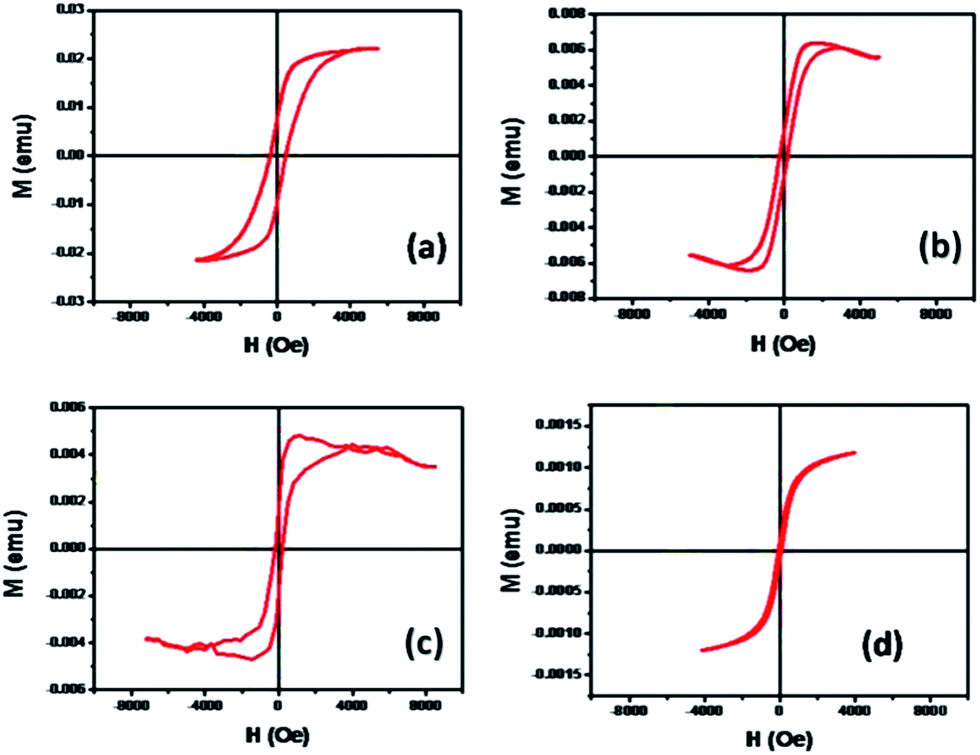 | ||
| Fig. 11 Hysteresis loops of Au nanoparticles with different concentration of Co2+ ions (a) 7.5 × 10⁻⁴ M, (b) 5 × 10⁻⁴ M, (c) 2.5 × 10⁻⁴ M and (d) 1.25 × 10⁻⁴ M respectively. | ||
4. Conclusion
Hybrid magneto–plasmonic nanocomposites of controlled shapes (i.e. spheres and rod-like shape) had been prepared. Our method is based on seeded mediated method at which the magnetic nanoclusters have been used as a seed. We prepared hybrid Au–Co NRs and studied the physical properties of these hybrid nanostructure including optical and magnetic measurements. Our approach allows us to design different hybrid nanomaterials of controlled shape, optical and magnetic properties which has many promising applications in photonics, tharanostics and electronics.Acknowledgements
This Study supported by Science and Technology Development Fund (STDF) under grant ID: 1719, “Plasmonic-Semiconductor hybrid Nano-structural Solar Cells: toward Low Cost Great Enhancement of Solar Cell Efficiency”, and Swedish research foundation SIDA under grant 348-2007-6992.Notes and references
- R. Davis, Powder Technol., 2001, 119, 45 CrossRef.
- M. A. Kastner, Artificial Atoms Physics Today, 1993, 46, 24 CrossRef CAS PubMed.
- U. Kreibig and M. Vollmer, Optical Properties of Metal Clusters, Springer, Berlin, 1995 Search PubMed.
- G. C. Papavassiliou, Prog. Solid State Chem., 1979, 12, 185 CrossRef CAS.
- C. F. Bohren and D. R. Huffman, Absorption and Scattering of Light by Small Particles, Wiley, New York, 1983 Search PubMed.
- J. A. Creighton and D. G. Eadon, J. Chem. Soc., Faraday Trans., 1991, 87, 3881 RSC.
- G. Mie, Ann. Phys., 1908, 25, 377 CrossRef CAS PubMed.
- P. Mulvaney, Langmuir, 1996, 12, 788 CrossRef CAS.
- R. V. Gans, Ann. Phys., 1915, 47, 270 CrossRef CAS PubMed.
- S. Link and M. A. El-Sayed, Int. Rev. Phys. Chem., 2000, 19, 409 CrossRef CAS.
- S. Link and M. A. El-Sayed, Annu. Rev. Phys. Chem., 2003, 54, 331 CrossRef CAS PubMed.
- M. Kerker, The Scattering of Light and Other Electromagnetic Rediation, Academic, New York, 1969 Search PubMed.
- J. A. Scholl, A. L. Koh and J. A. Dionne, Nature, 2012, 483, 421 CrossRef CAS PubMed.
- E. A. Coronado, E. R. Encina and F. D. Stefani, Nanoscale, 2011, 3, 4042 RSC.
- W. A. Murray and W. L. Barnes, Adv. Mater., 2007, 19, 3771 CrossRef CAS PubMed.
- N. J. Halas, MRS Bull., 2005, 30, 362 CrossRef CAS.
- P. C. Angelomé, H. H. Mezerji, B. Goris, I. Pastoriza-Santos, J. Pérez-Juste, S. Bals and L. M. Liz-Marzán, Chem. Mater., 2012, 24, 1393 CrossRef.
- B. K. Juluri, Y. B. Zheng, D. Ahmed, L. Jensen and T. J. Huang, Chem. Commun., 2008, 112, 7309 CAS.
- B. Rodríguez-González, F. Attouchi, M. F. Cardinal, V. Myroshnychenko, O. Stéphan, F. J. G. de Abajo, L. M. Liz-Marzán and M. Kociak, Langmuir, 2012, 28, 9063 CrossRef PubMed.
- L. M. Liz-Marzan, Langmuir, 2006, 22, 32 CrossRef CAS PubMed.
- C. Noguez, J. Phys. Chem. C, 2007, 111, 3806 CAS.
- K. S. Lee and M. A. El-Sayed, J. Phys. Chem. B, 2006, 110, 19220 CrossRef CAS PubMed.
- C. Burda, X. Chen, R. Narayanan and M. A. El-Sayed, Chem. Rev., 2005, 105, 1025 CrossRef CAS PubMed.
- P. K. Jain, X. Huang, I. H. El-Sayed and M. A. El-Sayed, Acc. Chem. Res., 2008, 41, 1578 CrossRef CAS PubMed.
- S. Liu and Z. Tang, J. Mater. Chem., 2010, 20, 24 RSC.
- K. A. Willets and R. P. V. Duyne, Annu. Rev. Phys. Chem., 2007, 58, 267 CrossRef CAS PubMed.
- A. J. Haes, D. A. Stuart and R. P. V. Duyne, Nanotechnology in Biology and Medicine Methods, Devices, and Applications, CRC Press, 2007 Search PubMed.
- L. B. Sagle, L. K. Ruvuna, J. A. Ruemmele and R. P. Van Duyne, Nanomedicine, 2011, 6, 1447 CrossRef CAS PubMed.
- Z. Wang and L. Ma, Coord. Chem. Rev., 2009, 253, 1607 CrossRef CAS PubMed.
- K. A. Homan, J. Chen, A. Schiano, M. B. Mohamed, K. A. Willets, S. Murugesan, K. J. Stevenson and S. Emelianov, Adv. Funct. Mater., 2011, 21, 1673 CrossRef CAS PubMed.
- K. Wilson, K. Homan and S. Emelianov, Nat. Commun., 2012, 3, 618 CrossRef PubMed.
- K. Homan, M. Souza, R. Truby, G. P. Luke, C. Green, E. Vreeland and S. Emelianov, ACS Nano, 2012, 6, 641 CrossRef CAS PubMed.
- I. H. El-Sayed, X. Huang and M. A. El-Sayed, Nano Lett., 2005, 5, 829 CrossRef CAS PubMed.
- C. A. Loo, A. Lowery, N. Halas, J. West and R. Drezek, Nano Lett., 2005, 5, 709 CrossRef CAS PubMed.
- A. J. Haes and R. P. Van Duyne, J. Am. Chem. Soc., 2002, 124, 10596 CrossRef CAS PubMed.
- R. Elghanian, J. J. Storhoff, R. C. Mucic, R. L. Letsinger and C. A. Mirkin, Science, 1997, 277, 1078 CrossRef CAS.
- C. Sonnichsen, B. M. Reinhard, J. Liphardt and A. P. Alivisatos, Nat. Biotechnol., 2005, 23, 741 CrossRef PubMed.
- L. R. Hirsch, R. J. Stafford, J. A. Bankson, S. R. Sershen, B. Rivera, R. E. Price, J. D. Hazle, N. J. Halas and J. L. West, Proc. Natl. Acad. Sci. U. S. A., 2003, 100, 13549 CrossRef CAS PubMed.
- G. B. Scott and D. E. Lacklison, IEEE Trans. Magn., 1976, 12, 292 CrossRef.
- W. A. Murray and W. L. Barnes, Adv. Mater., 2007, 19, 3771 CrossRef CAS PubMed.
- E. Hao and G. C. Schatz, J. Chem. Phys., 2004, 120, 357 CrossRef CAS PubMed.
- L. A. Sweatlock, S. A. Maier, H. A. Atwater, J. J. Penninkhof and A. Polman, Phys. Rev. B: Condens. Matter Mater. Phys., 2005, 71, 235408 CrossRef.
- P. J. Schuck, D. P. Fromm, A. Sundaramurthy and G. Kino, Phys. Rev. Lett., 2005, 94, 017402 CrossRef CAS.
- M. S. Anderson, Appl. Phys. Lett., 2008, 92, 123101 CrossRef PubMed.
- G. C. Schatz and R. P. Van Duyne, Electromagnetic Mechanism of Surface-enhanced Spectroscopy, in Handbook of Vibrational Spectroscopy, ed. J. M. Chalmers and P. R. Griffiths, Wiley, New York, 2002, pp. 759–774 Search PubMed.
- E. Ozbay, Science, 2006, 311, 189 CrossRef CAS PubMed.
- J. B. González-Díaz, A. García-Martín, J. M. García-Martín, A. Cebollada, G. Armelles, B. Sepúlveda, Y. Alaverdyan and M. Käll, Small, 2008, 4, 202 CrossRef PubMed.
- G.-F. Wang, M. A. Van Hove, P. N. Ross and M. I. Baskes, J. Chem. Phys., 2005, 122, 024706 CrossRef PubMed.
- C. Wang, H. Yin, R. Chan, S. Peng, S. Dai and S. Sun, Chem. Mater., 2009, 21, 433 CrossRef CAS.
- M. Abe and T. Suwa, Phys. Rev. B: Condens. Matter Mater. Phys., 2004, 70, 235103 CrossRef.
- H. Y. Wu, C. J. Choi and B. T. Cunningham, Small, 2012, 8, 2878 CrossRef CAS PubMed.
- W. Shi, H. Zeng, Y. Sahoo, T. Y. Ohulchanskyy, Y. Ding, Z. L. Wang, M. Swihart and P. N. Prasad, Nano Lett., 2006, 6, 875 CrossRef CAS PubMed.
- L. Carbone and P. D. Cozzoli, Nano Today, 2010, 5, 449 CrossRef CAS PubMed.
- M. Shim and H. McDaniel, Curr. Opin. Solid State Mater. Sci., 2010, 14, 83 CrossRef CAS PubMed.
- T. Teranishi, Y. Inoue, M. Nakaya, Y. Oumi and T. Sano, J. Am. Chem. Soc., 2004, 126, 9914 CrossRef CAS PubMed.
- T. Teranishi, M. Saruyama, M. Nakaya and M. Kanehara, Angew. Chem., 2007, 119, 1743 CrossRef PubMed.
- W. Shi, Y. Sahoo, H. Zeng, Y. Ding, M. T. Swihart and P. N. Prasad, Adv. Mater., 2006, 18, 1889 CrossRef CAS PubMed.
- O. Pana, C. M. Teodorescu, O. Chauvet, C. Payen, D. Macovei, R. Turcu, M. L. Soran, N. Aldea and L. Barbu, Surf. Sci., 2007, 601, 4352 CrossRef CAS PubMed.
- F. Wetz, K. Soulantica, A. Falqui, M. Respaud, E. Snoeck and B. Chaudret, Angew. Chem., 2007, 119, 7209 CrossRef PubMed.
- D. Poondi and J. Singh, J. Mater. Sci., 2000, 35, 2467 CrossRef CAS.
- G. Armelles, J. B. González-Díaz, A. García-Martín, J. M. García-Martín, A. Cebollada, M. U. González, S. Acimovic, J. Cesario, R. Quidant and G. Badenes, Opt. Express, 2008, 16, 16104 CrossRef CAS.
- J. F. Torrado, J. B. González-Díaz, M. U. González, A. García-Martín and G. Armelles, Opt. Express, 2010, 15, 15635 CrossRef PubMed.
- V. V. Temnov, G. Armelles, U. Woggon, D. Guzatov, A. Cebollada, A. Garcia-Martin, J. Garcia-Martin, T. Thomay, A. Leitenstorfer and R. Bratschitsch, Nat. Photonics, 2010, 4, 107 CrossRef CAS.
- (a) D. P. Kumah, A. Cebollada, C. Clavero, J. R. Garćıa-Martín, J. M. Skuza, R. A. Lukaszew and R. Clarke1, J. Phys. D: Appl. Phys., 2007, 40, 2699 CrossRef CAS; (b) K. Schouteden and C. Van Haesendonck, J. Phys.: Condens. Matter, 2010, 22, 255504 CrossRef CAS PubMed.
- V. I. Belotelov, L. L. Doskolovich and A. K. Zvezdin, Phys. Rev. Lett., 2007, 98, 077401 CrossRef CAS.
- C. J. Johnson, E. Dujardin, S. A. Davis, C. J. Murphy and S. Mann, J. Mater. Chem., 2002, 12, 1765 RSC.
- B. Nikoobakht and M. A. El-Sayed, Chem. Mater., 2003, 15, 1957 CrossRef CAS.
- D. A. Handley, Colloidal Gold: properties, Methods, and Application, Academic Press, New York, 1989 Search PubMed.
- J. Lin, W. Zhou, A. Kumbhar, J. Wiemann, J. Fang, E. E. Carpenter and C. J. O'Connor, J. Solid State Chem., 2001, 159, 26 CrossRef CAS.
- Y. Bao, H. Calderon and K. M. Krishnan, J. Phys. Chem. C, 2007, 111, 1941 CAS.
- G. Cheng and A. R. H. Walker, J. Magn. Magn. Mater., 2007, 311, 31 CrossRef CAS PubMed.
- J. L. Lyon, D. A. Fleming, M. B. Stone, P. Schiffer and M. E. Williams, Nano Lett., 2004, 4, 719 CrossRef CAS.
- A. C. Templeton, J. J. Pietron, R. W. Murray and P. Mulvaney, J. Phys. Chem. B, 2000, 104, 564 CrossRef CAS.
- E. Girgis, W. K. B. Khalil, A. N. Emam, M. B. Mohamed and K. V. Rao, Chem. Res. Toxicol., 2012, 25, 1086 CrossRef CAS PubMed.
- A. Ledo-Suárez, J. Rivas, C. F. Rodríguez-Abreu, M. J. Rodríguez, E. Pastor, A. Hernández-Creus, S. B. Oseroff and M. A. López-Quintela, Angew. Chem., Int. Ed., 2007, 46, 8823 CrossRef PubMed.
- M. J. Rodríguez-Vázquez, M. C. Blanco, R. Lourido, C. Vázquez-Vázquez, E. Pastor, G. A. Planes, J. Rivas and M. A. López-Quintela, Langmuir, 2008, 24, 12690 CrossRef PubMed.
- S. Özkar and R. G. Finke, Langmuir, 2002, 18, 7653 CrossRef.
- M. T. Reetz and M. Maase, Adv. Mater., 1999, 11, 773 CrossRef CAS.
- S. Link, M. B. Mohamed and M. A. El-Sayed, J. Phys. Chem. B, 1999, 103, 3073 CrossRef CAS.
- P. Boyer, D. Ménard and M. Meunier, J. Phys. Chem. C, 2010, 114, 13497 CAS.
- Z. Xu, Y. Hou and S. Sun, J. Am. Chem. Soc., 2007, 129, 8698 CrossRef CAS PubMed.
- G. C. Lica, B. S. Zelakiewicz, M. Constantinescu and Y. Y. Tong, J. Phys. Chem. B, 2004, 108, 19896 CrossRef CAS.
- M. Liu and P. Guyot-Sionnest, J. Phys. Chem. B, 2005, 109, 22192 CrossRef CAS PubMed.
- H. Khatri, G. Packiaraj and R. B. Jotania, Adv. Mater. Res., 2014, 938, 14 CrossRef CAS.
- W. E. N. Shu-lai, C. Jing-wei, L. Hong, L. Ying, Z. Xiu-chen and W. Yu-Feng, J. Mater. Eng., 2014,(8), 21 Search PubMed.
- P. Crespo, R. Litrán, T. C. Rojas, M. Multigner, J. M. De la Fuente, J. C. Sánchez-López, M. A. Garcia, A. Hernando, S. Penadés and A. Fernández, Phys. Rev. Lett., 2004, 93, 087204 CrossRef CAS.
| This journal is © The Royal Society of Chemistry 2015 |