Hollow Co3O4 microspheres with nano-sized shells: one-step large-scale synthesis, growth mechanism and supercapacitor properties
Chao Fenga,
Jinfeng Zhangb,
Yida Deng*b,
Cheng Zhongb,
Lei Liua and
Wenbin Hu*ab
aState Key Laboratory of Metal Matrix Composites, School of Material Science and Engineering, Shanghai Jiao Tong University, Shanghai 200240, People’s Republic of China. E-mail: wbhu@263.net
bSchool of Material Science and Engineering, Tianjin University, Tianjin 300072, People’s Republic of China. E-mail: yida.deng@tju.edu.cn
First published on 15th April 2015
Abstract
Hollow Co3O4 microspheres with thin spherical shells were produced using a one-step method at a low hydrothermal temperature (120 °C), and could be obtained without the use of a solid template, organic reagent or subsequent calcination. These hollow Co3O4 microspheres possess a diameter of ca. 500 nm and a thin shell thickness of ca. 50 nm. The samples were characterized by field emission scanning electron microscope (SEM), transmission electron microscope (TEM) and powder X-ray diffraction (PXRD). A multistep-splitting growth mechanism was proposed to reveal the formation of hollow Co3O4 microspheres. The successful fabrication of the hollow spherical morphology of these microspheres highlighted the importance of H2O2 dosage and the nitrate concentration. Electrochemical performance tests of the as-prepared samples indicated that the hollow Co3O4 microspheres exhibited ultrahigh specific capacitances of 1227, 1169, 1116, 1035 F g−1 at current densities of 1, 2, 4, 8 A g−1, respectively. After 1000 cycles, the specific capacitance of hollow Co3O4 microspheres showed high charge–discharge reversibility and only a slight decay of less than 3% at a current density of 2 A g−1.
1. Introduction
To meet the ever-expanding energy demand of the new industrial age, research has been intensely undertaken to explore high capacity and power substitute electrode materials for traditional carbon, striving to improve the efficiency of energy utilization.1–11 Recently research has been focused on two main aspects: (a) chemical modification and embellishment of traditional carbon has become common practice, for example, adopting carbon nanotubes (CNTs), graphene or other materials with high electrochemical activity seems to be one appropriate option; (b) other pseudocapacitance materials which store energy on the basis of fast reversible redox reactions occurring within these electroactive materials owing to several oxidation states have been investigated.As a result, various transition metal oxides as a class of ideal materials have drawn intense attention mainly due to their good specific capacitance,12 long cycle life and fast redox kinetics.13 For instance, RuO2,14,15 Co3O4,16 NiO,17,18 MnO2![[thin space (1/6-em)]](https://www.rsc.org/images/entities/char_2009.gif) 19,20 are considered to be the most desirable candidate materials for electrochemical capacitor (EC) application. Recent studies revealed that Co3O4 is a promising alternative choice for carbon-based materials on account of its high capacitance (theoretical value to 3560 F g−1), excellent reversible redox behavior, good corrosion stability and benign environmental friendliness.21 In order to improve the electrochemical performance of this type of material, it is appropriate to seek materials with higher specific surface area and easier electrolyte-accessibility. Because the unique structure of Co3O4 facilitates ion diffusion and mitigates the expansion of the lattice spacing of electrode materials, countless attempts have been made to synthesize Co3O4 of different morphologies such as wires,22,23 tubes,24 walls,25 urchin-like structures.26 Nevertheless, in consideration of the thermal stress influence during the continuous electrochemical test, a hollow morphology will probably be the most stable structure from the point of view of structural and thermal stability. Based on this viewpoint, researchers have devoted themselves to develop hollow Co3O4 nanoparticles using a variety of techniques.27,28 However, there were still obstacles to the manufacture of hollow Co3O4 spheres in a comparatively simple and efficient way. On the one hand, Ma and Manthiram’s teams have both prepared hollow Co3O4 spheres or 3D hierarchical Co3O4 twin-spheres by annealing urchin-like hollow Co(CO3)0.5(OH)·0.11H2O which acted as the precursor of a morphology template.29 The spherical morphology was damaged to some extent by the calcining process. On the other hand, in Sun’s latest work, they decorated hollow Co3O4 nanospheres with graphene with the aim of improving the electrochemical performance of Co3O4, and thus increased the application costs and complicated the preparation procedure.30 Therefore, it still remains a huge challenge to synthesize high performance hollow Co3O4 spheres in a low cost and effective way.
19,20 are considered to be the most desirable candidate materials for electrochemical capacitor (EC) application. Recent studies revealed that Co3O4 is a promising alternative choice for carbon-based materials on account of its high capacitance (theoretical value to 3560 F g−1), excellent reversible redox behavior, good corrosion stability and benign environmental friendliness.21 In order to improve the electrochemical performance of this type of material, it is appropriate to seek materials with higher specific surface area and easier electrolyte-accessibility. Because the unique structure of Co3O4 facilitates ion diffusion and mitigates the expansion of the lattice spacing of electrode materials, countless attempts have been made to synthesize Co3O4 of different morphologies such as wires,22,23 tubes,24 walls,25 urchin-like structures.26 Nevertheless, in consideration of the thermal stress influence during the continuous electrochemical test, a hollow morphology will probably be the most stable structure from the point of view of structural and thermal stability. Based on this viewpoint, researchers have devoted themselves to develop hollow Co3O4 nanoparticles using a variety of techniques.27,28 However, there were still obstacles to the manufacture of hollow Co3O4 spheres in a comparatively simple and efficient way. On the one hand, Ma and Manthiram’s teams have both prepared hollow Co3O4 spheres or 3D hierarchical Co3O4 twin-spheres by annealing urchin-like hollow Co(CO3)0.5(OH)·0.11H2O which acted as the precursor of a morphology template.29 The spherical morphology was damaged to some extent by the calcining process. On the other hand, in Sun’s latest work, they decorated hollow Co3O4 nanospheres with graphene with the aim of improving the electrochemical performance of Co3O4, and thus increased the application costs and complicated the preparation procedure.30 Therefore, it still remains a huge challenge to synthesize high performance hollow Co3O4 spheres in a low cost and effective way.
In this article, we report the preparation of hollow Co3O4 microspheres without the assistance of a solid template and a subsequent calcination process. As is known for the synthesis of Co3O4 through various means, the oxidation of Co(II) to Co(III) remains as an unavoidable obstacle. For the purpose of solving this problem, previous researchers either adopted an electrodeposition method or a hydrothermal process followed by high temperature calcination. In this study, the main innovation in the synthesis of hollow Co3O4 microspheres not only lay in taking advantage of the easy oxidation of Co(NH3)62+ to realize Co2+ → Co3+ at a low temperature (120 °C), but also paid attention to manufacturing hollow structures with the help of air bubbles. Moreover, the electrochemical performance of the hollow Co3O4 microspheres exhibited ultrahigh specific capacitances of 1227, 1169, 1116 and 1035 F g−1 at current densities of 1, 2, 4, 8 A g−1, respectively. The supercapacitor constructed with the hollow Co3O4 microspheres also showed an excellent reversibility with an efficiency of 97.5% after 1000 cycles at a current density of 2 A g−1. The amazing electrochemical properties could be ascribed to the greatly increased number of active sites and greatly shortened ion diffusion distances of this hollow structure.
2. Experimental section
2.1 Materials
Cobalt nitrate (Co(NO3)2, analytical grade), sodium nitrate (NaNO3, ≥99.5%), ammonium hydroxide (NH3·H2O, 25%∼28%), hydrogen peroxide (H2O2, 30%) were used. All reagents were purchased from Sinopharm Chemical Reagent Co., Ltd. and were used as received. The deionized water used in all experiments with a resistivity of 18.2 MΩ cm was prepared using an ultrapure water system (Millipore).2.2 Preparation of hollow Co3O4 microspheres
In a typical synthesis, 10 mM Co(NO3)2 and 10 mM NaNO3 were dissolved in 20.0 mL of deionized water to form a homogeneous solution. Then 10 mL NH3·H2O was added dropwise to the mixed solution with constant stirring in air for about 30 min. After the addition of 4 mL of H2O2, the mixture was sealed in a 200 mL Teflon-lined stainless steel autoclave and transferred into a homogeneous reactor set at 120 °C for 12 h. After the reactor had cooled to room temperature, the samples were rinsed three times with deionized water and ethanol, respectively, and dried in a conventional oven. Black powders of hollow Co3O4 microspheres were obtained.2.3 Materials characterization
The morphologies and structures of the product were analyzed by field emission scanning electron microscope (FE-SEM) and transmission electron microscope (TEM). FESEM characterization was performed on a JSM-7600F. TEM investigation was carried out using a high-resolution transmission electron microscope (HR-TEM, JEOL, JEM-2100F) operated at 200 kV. All samples were dispersed in absolute ethanol solution and then dropped on a copper gird. Selected area electron diffraction (SAED) was also performed via the previous TEM. The phase purity of the as-prepared sample was characterized by X-ray diffraction (D/max 2550VL/PC) with Cu Kα radiation from 10° to 80° at a scanning rate of 4° min−1. The X-ray tube voltage and current were set at 35 kV and 200 mA, respectively. The Raman spectrum of the sample was collected on SenterraR200-L Raman system with 532 nm diode laser excitation at room temperature.2.4 Electrochemical measurements
The electrochemical studies were performed in a conventional three-electrode system with a KOH electrolyte solution (2 mol L−1). The newly produced hollow Co3O4 microspheres loaded on nickel foam, a platinum electrode, and a saturated calomel electrode (SCE) were used as the working electrode, counter electrode and reference electrode, respectively. The working electrode was composed of active Co3O4 material (75 wt%), carbon black (15 wt%) and binder (PTFE, 10 wt%). The mixture was first coated onto the surface of a piece of nickel foam sheet (1 cm × 1 cm), and dried at 65 °C overnight. The sheets with active materials were finally pressed under 14 MPa to obtain the working electrode. The loading weight of hollow Co3O4 microspheres on the nickel foam sheet was 0.67 mg cm−2. The cyclic voltammogram (CV), galvanostatic charge–discharge cycle tests and electrochemical impedance spectroscopy (EIS) were performed on a CHI 660E electrochemical workstation. The EIS measurements were performed from the frequency window of 0.01 to 100 KHz at an open-circuit potential with an ac perturbation of 5 mV.3. Results and discussion
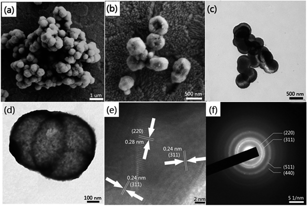
The morphologies of the as-obtained samples were characterized by field emission scanning electron microscope (FE-SEM) and transmission electron microscope (TEM). The SEM image shows the samples possess homogeneous diameters of ca. 500 nm and most of the samples are of intact spherical morphology (see in Fig. 1a). From the amplified SEM image of broken hollow microspheres in Fig. 1b, we could evaluate that the shell thickness was about 50 nm. It can be seen from Fig. 1c that the hollow Co3O4 microspheres exhibit a distinct hollow feature and with a thin-walled shell. In addition, the high magnification TEM image (as shown in Fig. 1d) distinctly reveals the thin shell trait with a shell thickness about 50 nm. The structures of hollow Co3O4 microspheres were further examined by high-resolution transmission electron microscopy (HR-TEM) and selected area electron diffraction (SAED). As displayed in Fig. 1e, the d-spacings of the hollow microspheres are approximately 0.28 and 0.24 nm, corresponding to the (220) and (311) planes of cubic Co3O4. The clear lattice fringes indicate that the microspheres are composed of many nanocrystalline features with high crystallinity. The distinctive diffraction rings in Fig. 1f further confirm their polycrystalline features, which from the center could determined to be (220), (311), (511) and (440) crystal planes.Raman analysis was also employed to characterize the optical properties of the hollow Co3O4 microspheres. As depicted in Fig. 2a, five apparent Raman peaks were located at 185, 480, 512, 593, 653 cm−1, respectively. These peaks correspond to three F2g, one Eg, and one A1g Raman-active modes of the Co3O4 microcrystals as marked in Fig. 2a. The values are in close proximity to standard microcrystalline Co3O4 powders.31 This result indicates that the as-prepared samples are Co3O4 crystallized in the form of a normal spinel structure with Co2+and Co3+ being located at the tetrahedral and octahedral sites, respectively. Furthermore, samples synthesized at different hydrothermal temperatures were characterized by PXRD analysis. As illustrated in Fig. 2b, all the diffraction peaks could be indexed as the standard PDF card (JCPDS card no. 43-1003) and agree with the characteristics of cubic spinel Co3O4 (Fd3m, a = 8.804 Å). There were no diffraction peaks from any other impurities, which implied the high purity of the Co3O4 microspheres. The samples obtained at 100 °C exhibited poor crystallization properties. However, accompanied by a rise in hydrothermal temperature, the crystal plane intensity of (111) which was closely related to Co(II) of spinel Co3O4 slightly dropped. In contrast, the intensities of the (311), (400), (511) and (440) crystal plane related to Co(III) increased visibly. This phenomenon reflected the fact that a higher hydrothermal temperature accelerates the oxidation rate of Co(II). This also explains why researchers used to manufacture Co3O4 materials in two steps composed of the synthesis of Co(OH)2 precursor and a high temperature calcination oxidation process (>260 °C).
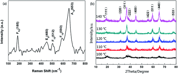 | ||
| Fig. 2 (a) Raman spectra of hollow Co3O4 microspheres, (b) XRD patterns of products which were synthesized at different hydrothermal temperatures. | ||
In this study, to obtain Co3O4 in one-step, we introduced cobalt complexed with ammonia into the system. Here we show the corresponding Nernst equations of Co(II) to Co(III) under two totally different reaction conditions:
| [Co(H2O)6]3+ + e− ↔ [Co(H2O)6]2+, φθ = 1.80 V | (1) |
| [Co(NH3)6]3+ + e− ↔ [Co(NH3)6]2+, φθ = 0.18 V | (2) |
Eqn (1) represents the general conversion of Co(II) to Co(III) in ordinary alkaline solution. However, when the concentration of NH3 is comparatively high in the solution, the former ligand (H2O) of Co2+ would inevitably be replaced by NH3 due to the much bigger coordination stability constant of the latter.32 Obviously, we successfully lowered the reaction thermodynamics of this transformation process by introducing NH3. Therefore, Co3O4 materials could be synthesized in one-step with an extremely low hydrothermal temperature (120 °C).
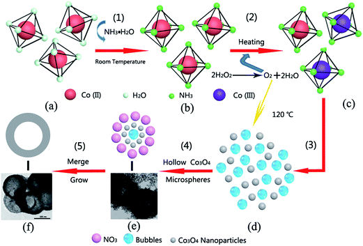
Fig. 3 shows a schematic diagram of the synthesis of the corresponding hollow Co3O4 microspheres. At step (1), [Co(NH3)6]2+ (Fig. 3b) is generated at room temperature. It is rapidly oxidized to [Co(NH3)6]3+ (Fig. 3c) by O2 resulting from the immediate decomposition of H2O2 as illustrated in step (2). Then under the hydrothermal conditions, on account of the low coordination stability constant of [Co(NH3)6]2+ (1.3 × 10⁵),33 simultaneous reactions took place [step (3)]. Under these conditions, massive nanoparticles of Co3O4 were produced via the recrystallization process (as displayed in Fig. 3d). Next, the O2 bubbles that were constantly produced due to the decomposition of H2O2 serve as the center of core–shell structure formation. The vast bubbles which exist in the reaction solution tremendously favor the formation of the hollow structure. As shown in step (4), temporary core–shell structures (Fig. 3e) were formed, and numerous replication products emerged continuously. TEM images of intermediate products during the preparation process are also shown in Fig. 3e. It can be seen that the bodies of the hollow Co3O4 microspheres were composed of small Co3O4 nanoparticles with size of several nanometers. Taking into consideration the abundant nitrate co-existing in the hydrothermal solution, this would affect the growth stage by selectively changing the growth kinetics of the different crystals.34 In addition, because of the large c-axis distance and charge balance, the nitrate is apt to insert into the Co–O bond,35 hence the surface of Co3O4 nanoparticles were wrapped up by the nitrate. As a result, the disorder attraction of interatomic forces was deliberately interfered with, and the newly-generated hollow intermediate structures were able to keep evolving in situ isolated from each other. Under the twin impacts of the driving force of reducing surface energy and the effect of nitrate, encapsulated Co3O4 nanoparticles continued to grow and merge with adjacent nanoparticles to form hollow microspheres (Fig. 3f) as shown in step (5).
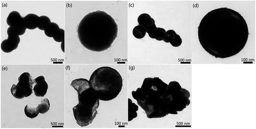
Based on the formation process mentioned above, H2O2 dosage and nitrate concentration seem to play irreplaceable mutual roles on facilitating the synthesis of hollow Co3O4 microspheres. Hence, we carried out two control experiments to investigate the effect H2O2 and nitrate exerted on the Co3O4 crystal growth. However, the bubbles stemming from the decomposition of H2O2 would serve as templates for the inner cavities of microspheres during the hydrothermal conditions. Taking into account the situation that a proportion of the O2 has already been consumed in the oxidation conversion of [Co(NH3)6]2+ to [Co(NH3)6]3+, the H2O2 dosage is directly related to the size and quality of the microsphere cavity. In a typical synthesis of hollow Co3O4 microspheres, the H2O2 dosage is 4 mL. However, an inadequate H2O2 dosage would lead to the fabrication of solid microspheres rather than hollow ones. Fig. 4a and b represents the TEM image of microspheres with a H2O2 dosage of 2 mL. The formation of solid Co3O4 microspheres (as shown in Fig. 4b) is evidence that insufficient bubbles were present to act as the cavity template. When the H2O2 dosage was increased to 3 mL, hollow Co3O4 microspheres started to emerge and coexist with solid Co3O4 microspheres in the final product as shown in Fig. 4c. In combination with the TEM image of Fig. 4d, it is observed that inner cavities were unevenly distributed due to a deficiency of bubbles. On the other hand, an excess of H2O2 would also have a negative effect on the synthesis process. As seen in Fig. 4e and f although the bubbles could act as a template of the hollow structure, there was also a side-effect which cannot be ignored. The disturbance of the bubbles is aggravated due to the increase of H2O2 (5 mL), which caused severe damage to the formation and growth of shell structures (as shown in Fig. 4e). In this case, a large number of shell fragments coexisted with the integrated hollow microspheres in the final products. As the H2O2 dosage (6 mL) was increased, the tremendous amount of bubbles totally destroyed the hollow structures, and as a result, blocky-shaped particles with voids were generated instead of hollow Co3O4 microspheres (as displayed in Fig. 4g).
Fig. 5 shows the TEM images of various samples, which were prepared with different nitrate concentrations but keeping the other parameters constant. It can easily be seen from Fig. 5a that a severe deficiency of nitrate (0.5 M) is unable to cover all the newly-produced Co3O4 nanocrystals in this situation. As a result, in spite of the formation of an inner cavity caused by the bubbles, the majority of nanocrystals reunited with each other to grow into blocky-shaped particles with voids (as shown in Fig. 5b). When nitrate concentration was increased (0.75 M), the agglomeration phenomena were alleviated to some extent. As seen in Fig. 5c, an increase in nitrate concentration promoted hollow microsphere formation. With the assistance of nitrate inserting into the Co–O bond, a substantial amount of the particles were of spherical morphology. Fig. 5d shows the TEM image of twin hollow microspheres that share the same internal cavity. The nitrate concentration of 1 M adopted in the typical synthesis process as shown in the experimental section turned out to be the optimum parameter that most benefits the preparation of hollow Co3O4 microspheres. As the concentration continued to be increased, the amount of nitrate surpassed the appropriate dosage needed for creating Co3O4 microspheres with uniform size of 500 nm. As shown in Fig. 5e, some of the hollow Co3O4 microspheres possess a larger size than 500 nm and a magnified hollow Co3O4 microsphere shows the diameter of ca. 550 nm (as shown in Fig. 5f). When the concentration of nitrate was increased to 1.5 M, the size of these as-obtained hollow Co3O4 microspheres was no longer homogeneous as shown in Fig. 5g and h, which could surely be ascribed to the superfluous nitrate. Because under the hydrothermal conditions, excess nitrate provided a bigger cladding surface area for Co3O4 microspheres thus weakening the size restriction in the process of Co3O4 nanocrystal growth.
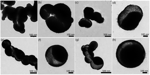 | ||
| Fig. 5 (a), (c), (e), and (g) TEM image and (b), (d), (f), and (h) high magnification image of the as-prepared samples with nitrate concentration at 0.5, 0.75, 1.25, 1.5 M, respectively. | ||
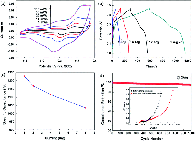
The electrochemical performances of the as-obtained hollow Co3O4 microspheres were investigated by CV, galvanostatic charge–discharge tests and EIS. The CVs of the hollow Co3O4 microspheres were recorded at different scan rates and in a potential range of −0.25–0.55 V (vs. SCE). All the curves show obvious pseudocapacitance features with a similar line type as shown in Fig. 6a. It can be observed in the graph that the cathodic scan of the CV curves did not match well with the corresponding anodic ones, which demonstrates that polarizations exist in the Faradaic redox reactions.36
The pseudo-capacitances of the hollow Co3O4 microspheres were elucidated by galvanostatic charge–discharge tests in the potential range of 0–0.47 V. The specific capacitance of the supercapacitors could be evaluated from the charge–discharge tests together with the following equation:37
| Cm = IΔt/mΔV | (3) |
Cycling stability is another key index for the supercapacitors to possess application potential. As seen in Fig. 5d, after cycling 1000 times, the capacitance of the electrode made of hollow Co3O4 microspheres only slightly decreased to approximately 97.5% of its maximum value, which indicated its excellent reversibility. This result is also consistent with the EIS curve in Fig. 6d inset. Obviously the internal resistance of the solution remained almost the same after the cycling test, and the charge transfer resistance had undergone a slight increase. The internal cavity of hollow Co3O4 microspheres could provide a buffer for the thermal expansion during the electrochemical process. In addition, the thin shells of the hollow Co3O4 microspheres also keep the concentration of the solution even by facilitating ion transport. Therefore, even after a long cycle of 1000 times, the electrode structure is basically kept intact.
4. Conclusions
In this report, hollow Co3O4 microspheres with thin shells of 50 nm were synthesized by a one-step hydrothermal method at low temperature (120 °C). By means of taking advantages of the mutual influences of nitrate and H2O2, hollow Co3O4 microspheres with thin shells were obtained for the first time with the absence of a morphology template, organic reagent and additional calcination. Subsequent electrochemical evaluation showed that hollow Co3O4 microspheres possess a maximum specific capacitance of 1227 F g−1 and 97.5% of the initial value even after a long cycling test of 1000 times. This tremendous superiority could be ascribed to the hollow nanostructure and thin shell, which not only greatly increased the active sites of electrode materials and shortened ion transfer distance but also offered a buffer for the thermal expansion during the electrochemical process. This study provided insight into the synthetic control of nanostructures based on managing micro-reaction conditions.Acknowledgements
This work was supported by the National Science Fund for Distinguished Young Scholars (no. 51125016), and the National Natural Science Foundation of China (no. 51472178, no. 51371119).Notes and references
- G. P. Wang, L. Zhang and J. J. Zhang, Chem. Soc. Rev., 2012, 41, 797–828 RSC.
- J. B. Goodenough and K. S. Park, J. Am. Chem. Soc., 2013, 135, 1167–1176 CrossRef CAS PubMed.
- W. Q. Zeng, F. P. Zheng, R. Z. Li, Y. Zhan, Y. Y. Li and J. P. Liu, Nanoscale, 2012, 4, 2760–2765 RSC.
- Y. Zhang, B. Cui, O. Derr, Z. B. Yao, Z. T. Qin, X. Y. Deng, J. B. Li and H. Lin, Nanoscale, 2014, 6, 3376–3383 RSC.
- X. Li, W. Sun, L. Wang, Y. Qi, T. Guo, X. Zhao and X. Yan, RSC Adv., 2015, 5, 7976–7985 RSC.
- K. Shi and I. Zhitomirsky, RSC Adv., 2015, 5, 320–327 RSC.
- M. Kuang, Y. X. Zhang, T. T. Li, K. F. Li, S. M. Zhang, G. Li and W. Zhange, J. Power Sources, 2015, 283, 270–278 CrossRef CAS PubMed.
- G. Nagaraju, Y. H. Ko and J. S. Yu, J. Power Sources, 2015, 283, 251–259 CrossRef CAS PubMed.
- P. Yan, R. Zhang, J. Jia, C. Wu, A. Zhou, J. Xu and X. Zhang, J. Power Sources, 2015, 284, 38–43 CrossRef CAS PubMed.
- Y. Chen and J. L. Shi, Sci. China Mater., 2015, 58, 241–257 CrossRef PubMed.
- C. Wu, L. X. Yuan, Z. Li, Z. Q. Yi, R. Zeng, Y. R. Li and Y. H. Huang, Sci. China Mater., 2015, 58, 91–97 CrossRef PubMed.
- H. Jiang, T. Zhao, C. Y. Yan, J. Ma and C. Z. Li, Nanoscale, 2010, 2, 2195–2198 RSC.
- H. L. Wang, H. S. Casalongue, Y. Y. Liang and H. J. Dai, J. Am. Chem. Soc., 2010, 132, 7472–7477 CrossRef CAS PubMed.
- T. M. Dinh, A. Achour, S. Vizireanu, G. Dinescu, L. Nistor, K. Armstrong, D. Guay and D. Pech, Nano Energy, 2014, 10, 288–294 CrossRef CAS PubMed.
- C. Zhang, Y. Xie, M. Zhao, A. E. Pentecost, Z. Ling, J. Wang, D. Long, L. Ling and W. Qiao, ACS Appl. Mater. Interfaces, 2014, 6, 9751–9759 CAS.
- X. Wang, S. Yao, X. Wu, Z. Shi, H. Sun and R. Que, RSC Adv., 2015, 5, 17938–17944 RSC.
- F. Luan, G. M. Wang, Y. C. Ling, X. H. Lu, H. Y. Wang, Y. X. Tong, X. X. Liu and Y. Li, Nanoscale, 2013, 5, 7984–7990 RSC.
- M. B. Zakaria, M. Hu, R. R. Salunkhe, M. Pramanik, K. Takai, V. Malgras, S. Choi, S. X. Dou, J. H. Kim, M. Imura, S. Ishihara and Y. Yamauchi, Chem.–Eur. J., 2015, 21, 3605–3612 CrossRef CAS PubMed.
- M. K. Liu, W. W. Tjiu, J. S. Pan, C. Zhang, W. Gao and T. X. Liu, Nanoscale, 2014, 6, 4233–4242 RSC.
- M. Pang, G. Long, S. Jiang, Y. Ji, W. Han, B. Wang, X. Liu and Y. Xi, Electrochim. Acta, 2015, 161, 297–304 CrossRef CAS PubMed.
- B. R. Duan and Q. Cao, Electrochim. Acta, 2012, 64, 154–161 CrossRef CAS PubMed.
- S. L. Xiong, J. S. Chen, X. W. Lou and H. C. Zeng, Adv. Funct. Mater., 2012, 22, 861–871 CrossRef CAS PubMed.
- J. Zhang, W. Gao, M. Dou, F. Wang, J. Liu, Z. Li and J. Ji, Analyst, 2015, 140, 1686–1692 RSC.
- M. Chen, X. Xia, J. Yin and Q. Chen, Electrochim. Acta, 2015, 160, 15–21 CrossRef CAS PubMed.
- Y. H. Xiao, A. Q. Zhang, S. J. Liu, J. H. Zhao, S. M. Fang, D. Z. Jia and F. Li, J. Power Sources, 2012, 219, 140–146 CrossRef CAS PubMed.
- R. Edla, N. Patel, M. Orlandi, N. Bazzanella, V. Bello, C. Maurizio, G. Mattei, P. Mazzoldi and A. Miotello, Appl. Catal., B, 2015, 166–167, 475–484 CrossRef CAS PubMed.
- Y. H. Xiao, S. J. Liu, F. Li, A. Q. Zhang, J. H. Zhao, S. M. Fang and D. Z. Jia, Adv. Funct. Mater., 2012, 22, 4052–4059 CrossRef CAS PubMed.
- M. X. Liao, Y. F. Liu, Z. H. Hu and Q. Yu, J. Alloys Compd., 2013, 562, 106–110 CrossRef CAS PubMed.
- J. M. Ma and A. Manthiram, RSC Adv., 2012, 2, 3187–3189 RSC.
- H. T. Sun, X. Sun, T. Hu, M. P. Yu, F. Y. Lu and J. Lian, J. Phys. Chem. C, 2014, 118, 2263–2272 CAS.
- V. G. Hadjiev, M. N. Iliev and I. V. Vergilov, J. Phys. C: Solid State Phys., 1988, 21, L199 CrossRef.
- X. H. Xia, J. P. Tu, Y. J. Mai, X. L. Wang, C. D. Gu and X. B. Zhao, J. Mater. Chem., 2011, 21, 9319–9325 RSC.
- W. Y. Sun, Coordination Chemistry, Chemical Industry Press, Beijing, 2010 Search PubMed.
- L. W. Qian, J. T. Zai, Z. Chen, J. Zhu, Y. P. Yuan and X. F. Qian, CrystEngComm, 2010, 12, 199–206 RSC.
- H. Zhang, J. B. Wu, C. X. Zhai, X. Y. Ma, N. Du, J. P. Tu and D. R. Yang, Nanotechnology, 2008, 19, 035711 CrossRef PubMed.
- S. K. Meher, P. Justin and G. R. Rao, Nanoscale, 2011, 3, 683–692 RSC.
- M. S. Wu, Y. A. Huang and C. H. Yang, J. Electrochem. Soc., 2008, 155, A798–A805 CrossRef CAS PubMed.
- Y. Y. Wang, Y. Lei, J. Li, L. Gu, H. Y. Yuan and D. Xiao, ACS Appl. Mater. Interfaces, 2014, 6, 6739–6747 CAS.
- S. K. Meher and G. R. Rao, J. Phys. Chem. C, 2011, 115, 15646–15654 CAS.
| This journal is © The Royal Society of Chemistry 2015 |

