 Open Access Article
Sensitization of wide band gap photocatalysts to visible light by molten CuCl treatment†
Katsuya
Iwashina
a,
Akihide
Iwase
ab and
Akihiko
Kudo
*ab
aDepartment of Applied Chemistry, Faculty of Science, Tokyo University of Science, 1-3 Kagurazaka, Shinjuku-ku, Tokyo 162-8601, Japan. E-mail: a-kudo@rs.kagu.tus.ac.jp
bPhotocatalysis International Research Center, Research Institute for Science and Technology, Tokyo University of Science, 2641 Noda-shi, Yamazaki, Chiba-ken 278-8510, Japan
First published on 29th August 2014
Abstract
Cu(I)-substituted metal oxide photocatalysts were prepared using molten CuCl treatment of wide band gap photocatalysts. The Cu(I)-substituted metal oxide photocatalysts possessed a new absorption band in the visible light region and showed photocatalytic activity for hydrogen evolution from an aqueous solution containing sulfur sacrificial reagents under visible light irradiation. Notably, the Cu(I)–K2La2Ti3O10 and Cu(I)–NaTaO3 photocatalysts showed relatively high activities for hydrogen evolution and gave apparent quantum yields of 0.18% at 420 nm. These photocatalysts responded up to 620 nm. Thus, Cu(I)-substitution using a molten CuCl treatment was an effective strategy for sensitizing a metal oxide photocatalyst with a wide band gap to visible light.
Introduction
Solar water splitting using a photocatalyst is a candidate for the provision of an ultimately clean technology for hydrogen production to address energy and environmental issues. In order to achieve highly efficient solar water splitting, we need to develop photocatalysts which can utilize a wide range of visible light. Metal oxide photocatalysts generally possess wide band gaps, as O 2p orbitals form a deep valence band. Forming a new valence band is one of the strategies for the development of visible-light-driven photocatalysts.1 Ag(I),2 Sn(II)3 and Bi(III)4 are useful components for obtaining visible light responses in oxide photocatalysts with wide band gaps, because they form new valence bands at a more negative level than that consisting of O 2p orbitals. The fact that Cu(I) forms a shallower valence band than O 2p has been recently proven by the linear muffin-tin orbital (LMTO) method5 and the plane-wave density functional theory package CASTEP.6–8 Moreover, Cu(I) is a component that can form a new valence band which locates at a more negative level than that formed by Ag(I).9,10 Visible-light-driven photocatalysts containing Cu(I) were recently obtained through forming a solid solution.8,11 LiNb3O8–CuNb3O8 and Cu3Ta7O19–LaTa7O19 solid solutions show photocatalytic activity for hydrogen evolution from an aqueous methanol solution under visible light irradiation. Moreover, a Cu(I)-containing oxide electrode provided a cathodic photocurrent by water splitting under visible light irradiation.7 Cu(I) is a promising key component for developing a visible-light-driven photocatalyst, however it possesses problems with chemical and crystallographical stabilities. Cu(I) is easily oxidized to Cu(II) when a Cu(I)-containing oxide is prepared in air by a solid-state reaction. Moreover, Cu+ favors 2-coordination in a crystal structure of oxides.12 Therefore, only limited crystal structures are reported as a Cu(I)-containing oxide. In other words, the development of new Cu(I)-containing oxides is a challenging topic. Ion exchange by molten salt treatment is a useful technique for developing new oxide materials.13 We have previously developed a new material of AgLi1/3Ti2/3O2 with a delafossite structure by silver nitrate molten treatment of Li2TiO3.14 Cu(I)-containing oxides are also expected to be prepared by molten CuCl treatment. In this study, we prepared Cu(I)-containing metal oxide photocatalysts with not only layered but also bulky ilmenite and perovskite structures by using molten CuCl treatment. Their photocatalytic activities for hydrogen evolution were also evaluated under visible light irradiation.Experimental
Material synthesis
K4Nb6O17,15 KLaNb2O7,16 RbCa2Ta3O10,17 LiTaO3,18 NaTaO3![[thin space (1/6-em)]](https://www.rsc.org/images/entities/char_2009.gif) 18 and KTaO3
18 and KTaO3![[thin space (1/6-em)]](https://www.rsc.org/images/entities/char_2009.gif) 18 were prepared by a solid-state reaction, as previously reported. The starting materials used were as follows: Li2CO3 (Wako Pure Chemical; 99.0%), Na2CO3 (Kanto Chemical; 99.0%), K2CO3 (Kanto Chemical; 99.5%), Rb2CO3 (Kojundo Chemical; 99%), CaCO3 (Kanto Chemical; 99.5%), La2O3 (Kanto Chemical; 99.99%), Nb2O5 (Kojundo Chemical; 99.95%) and Ta2O5 (Rare Metallic; 99.99%). K2La2Ti3O10
18 were prepared by a solid-state reaction, as previously reported. The starting materials used were as follows: Li2CO3 (Wako Pure Chemical; 99.0%), Na2CO3 (Kanto Chemical; 99.0%), K2CO3 (Kanto Chemical; 99.5%), Rb2CO3 (Kojundo Chemical; 99%), CaCO3 (Kanto Chemical; 99.5%), La2O3 (Kanto Chemical; 99.99%), Nb2O5 (Kojundo Chemical; 99.95%) and Ta2O5 (Rare Metallic; 99.99%). K2La2Ti3O10![[thin space (1/6-em)]](https://www.rsc.org/images/entities/char_2009.gif) 19 was prepared using a polymerized complex method. The precursor was obtained from K2CO3 (Kanto Chemical; 99.5%), Ti(OC4H9)4 (Kanto Chemical; 97%), La(NO3)3 (Kanto Chemical; 99.99%), ethylene glycol (Kanto Chemical; 99.5%) and citric acid (Sigma Aldrich; 99.5%) by pyrolysis and was calcined at 1173 K for 2 h in air using an alumina crucible. CuCl was freshly prepared by reduction of CuCl2 (Wako Pure Chemical; 99.0%) with metallic Cu in boiling dilute hydrochloric acid. The molten CuCl treatment was carried out by immersing the prepared photocatalysts in molten CuCl at 773 K for 10 h in a quartz ampoule tube under vacuum. After the molten salt treatment, the excess CuCl was removed using an aqueous NH3 solution.
19 was prepared using a polymerized complex method. The precursor was obtained from K2CO3 (Kanto Chemical; 99.5%), Ti(OC4H9)4 (Kanto Chemical; 97%), La(NO3)3 (Kanto Chemical; 99.99%), ethylene glycol (Kanto Chemical; 99.5%) and citric acid (Sigma Aldrich; 99.5%) by pyrolysis and was calcined at 1173 K for 2 h in air using an alumina crucible. CuCl was freshly prepared by reduction of CuCl2 (Wako Pure Chemical; 99.0%) with metallic Cu in boiling dilute hydrochloric acid. The molten CuCl treatment was carried out by immersing the prepared photocatalysts in molten CuCl at 773 K for 10 h in a quartz ampoule tube under vacuum. After the molten salt treatment, the excess CuCl was removed using an aqueous NH3 solution.
Physical characterization
Crystal structures of the synthesized metal oxides were confirmed using powder X-ray diffraction (Rigaku; Mini Flex). Raman spectra were recorded with a Raman spectrometer (JASCO; RMP-5300). A green laser (532 nm) was used as the excitation source. Diffuse reflectance spectra were measured using a UV-vis-NIR spectrometer with an integrating sphere (JASCO; UbestV-570) and were converted from reflection to absorbance mode using the Kubelka–Munk method. The bulk composition analysis of the photocatalysts was investigated by X-ray fluorescence ((XRF) PANalytical; Epsilon5) and Inductively Coupled Plasma Atomic Emission Spectrometry ((ICP-AES) HITACHI; P-4010). Since the K2La2Ti3O10, with and without a molten CuCl treatment, can be dissolved in aqua regia, ICP-AES was employed for these samples. The compositions of the other samples were analyzed by XRF. Detailed experimental procedures are described in the ESI.† XPS and Auger spectra were obtained using X-ray photoelectron microscopy (JEOL; JPS-9010MC) in order to obtain the surface chemical states and the composition of the photocatalysts.Photocatalytic reaction
The photocatalytic hydrogen evolution from an aqueous potassium sulfite (0.5 mol L−1) and sodium sulfide (0.1 mol L−1) solution and the oxygen evolution from an aqueous silver nitrate solution (0.02 mol L−1) were carried out in a top-irradiation cell with a Pyrex window connected in a gas-closed-system. Photocatalyst powder (0.1–0.2 g) was dispersed in the reactant solution (120 mL). A Ru cocatalyst (0.3 wt%) was loaded in situ by a photodeposition method, using an aqueous RuCl3 solution. A 300 W Xe arc lamp (Perkin-Elmer: Cermax-PE300BF, monochromatic light intensity at 420 nm: ca. 5.3 mW cm−2) was employed as a light source. A cold mirror and cutoff filters (HOYA) were used to cut off IR and UV light, respectively. The amounts of evolved hydrogen and oxygen were determined using an online gas chromatograph (Shimazu; GC-8A, MS-5A column, TCD, Ar carrier). Apparent quantum yields were measured using a 100 W Xe arc lamp (Asahi Spectra; LAX-102) with band-pass filters (Asahi Spectra), a photodiode head (OPHIRA PD300-UV) and a NOVA power monitor, according to the following equation (eqn (1)): | (1) |
Results and discussion
Preparation and characterization of the Cu(I)-substituted layered photocatalysts
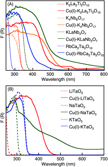
We examined the effect of a molten CuCl treatment on the physical properties of UV light-driven photocatalysts with a layered structure that showed activity towards water splitting. Fig. 1A shows the diffuse reflectance spectra of K2La2Ti3O10, K4Nb6O17, KLaNb2O7 and RbCa2Ta3O10, with and without molten CuCl treatment. The treated samples are denoted as Cu(I)–K2La2Ti3O10, Cu(I)–K4Nb6O17, Cu(I)–KLaNb2O7 and Cu(I)–RbCa2Ta3O10. Upon treating with molten CuCl, the absorption edges of all the photocatalysts red-shifted into the visible light region. The energy gaps of the photocatalysts treated with molten CuCl were 1.1–1.5 eV narrower than the band gaps of the non-treated photocatalysts. The new absorption bands in the visible light region were assigned to be due to the electronic transition from valence bands and/or electron donor levels consisting of substituted Cu(I) to conduction bands of the host materials, since their absorption profiles were different from those of Cu2O, CuO, CuCl and CuCl2 that might exist as impurities. | ||
| Fig. 1 Diffuse reflectance spectra of (A) K2La2Ti3O10, K4Nb6O17, KLaNb2O7 and RbCa2Ta3O10 layered oxides, and (B) LiTaO3, NaTaO3 and KTaO3 bulk oxides, before and after CuCl-treatment. | ||
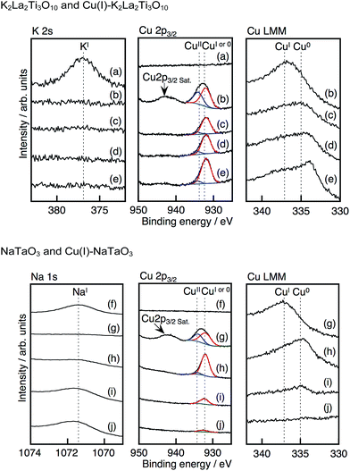
The ratio and valency of exchanged Cu were analyzed using XPS and Auger spectra as shown in Fig. 2. A K 2s peak and no Cu peaks were observed for non-treated K2La2Ti3O10. In contrast, the Cu 2p3/2 peaks, including Cu(II) with a satellite peak, appeared and the K 2s peak vanished after treatment with molten CuCl. An Auger LMM peak for Cu(I) was observed for the Cu(I)–K2La2Ti3O10. These results indicate that the Cu species present at the surface of the Cu(I)–K2La2Ti3O10 are a mixture of Cu(I) and Cu(II). The surface Cu(II) species probably formed when the treated sample was exposed in air. Cu 2p peaks, Auger LMM peaks and no K 2s peaks were observed even after Ar etching, while the Cu(II) species almost disappeared after Ar etching, indicating that all K+ ions in the interlayers had been exchanged for Cu+. The Auger LMM spectrum for Cu(0) became larger with the increased etching time. This is due to the reduction of Cu(I) during the Ar etching. No absorption spectrum due to metallic Cu was observed in Fig. 1A. Therefore, it is concluded that the main Cu species inside of Cu(I)–K2La2Ti3O10 is Cu(I).
 | ||
| Fig. 2 X-ray photoelectron and Auger spectra of (a) K2La2Ti3O10, (b–e) Cu(I)–K2La2Ti3O10 (f) NaTaO3, (g–j) Cu(I)–NaTaO3. Ar etching time: (b and g) 0 s, (c and h) 5 s, (d and i) 30 s, (j) 60 s and (e) 300 s. Peaks were assigned using ref. 20. | ||
The diffraction peak at around 10° for the layered structures of K2La2Ti3O10, K4Nb6O17, KLaNb2O7 and RbCa2Ta3O10 shifted to higher degree when they were treated with molten CuCl (Fig. S1†). These shifts indicate that K+ and Rb+ ions in the interlayers were exchanged for smaller Cu+ ions while keeping the layered structure, judging from the ionic radii (Cu+: 0.46 Å for 2 coordination, K+: 1.51 and 1.55 Å for 8 and 9 coordination, Rb+: 1.61 Å for 8 coordination).
Table 1 shows the Cu(I)-exchange ratio calculated from XRF and ICP results for the layered photocatalysts. More than half of the K+ and Rb+ in K2La2Ti3O10, K4Nb6O17, KLaNb2O7 and RbCa2Ta3O10 were exchanged for Cu+.
| Photocatalyst | Cu(I)-exchange ratio % | EG(BG)/eV | Sacrificial reagentd | H2-evolution/μmol h−1 | |
|---|---|---|---|---|---|
| Before CuCl-treatment | After CuCl-treatment | ||||
| a Catalyst: 0.1–0.2 g, cocatalyst: Ru (0.3 wt%), light source: 300 W Xe lamp (λ > 420 nm), top irradiation cell with Pyrex window. b Determined by ICP. c Determined by XRF. d Sacrificial reagent: 0.5 mol L−1 K2SO3aq. + 0.1 mol L−1 Na2Saq. (120 mL). | |||||
| Cu(I)–K2La2Ti3O10 | 100b | 3.5 | 2.0 | Yes | 12 |
| Cu(I)–K2La2Ti3O10 | 100b | 3.5 | 2.0 | No | None |
| K2La2Ti3O10 | 0b | 3.5 | — | Yes | 0.6 |
| Cu(I)–K4Nb6O17 | 69c | 3.3 | 2.2 | Yes | 0.25 |
| Cu(I)–KLaNb2O7 | 65c | 3.2 | 2.3 | Yes | 0.04 |
| Cu(I)–RbCa2Ta3O10 | 90c | 4.5 | 2.8 | Yes | 0.72 |
| Cu(I)–LiTaO3 | 2c | 4.8 | 2.8 | Yes | 0.18 |
| Cu(I)–NaTaO3 | 9c | 4.0 | 2.0 | Yes | 18 |
| Cu(I)–NaTaO3 | 9c | 4.0 | 2.0 | No | None |
| NaTaO3 | 0c | 4.0 | — | Yes | 0.03 |
| None | — | — | — | Yes | None |
Raman measurements also supported the Cu(I)-exchange conclusions (Fig. S2†). The band observed at 878 cm−1 on the Raman spectra of K2La2Ti3O10 was assigned to the large stretching motion of a double bond like Ti–O, which projects into the interlayer.21 The band was shifted towards a lower wavenumber by the molten CuCl treatment, because the bond order of the Ti–O bonds of Cu(I)–K2La2Ti3O10 were lower than that of K2La2Ti3O10. In general, the bond order of Ti–O bonds should decrease due to the formation of a covalent bond with Cu+ in the interlayer. Therefore, the band shift caused by the molten CuCl treatment was due to the exchange of K+ in the interlayer for Cu+.
Preparation and characterization of the Cu(I)-substituted bulky photocatalysts
We have also examined the effect of Cu(I)-substitution on the wide band gap photocatalysts of LiTaO3, NaTaO3 and KTaO3 with bulky ilmenite and perovskite structures, using molten CuCl treatment. The treated samples are denoted as Cu(I)–LiTaO3, Cu(I)–NaTaO3 and Cu(I)–KTaO3. The amounts of substituted Cu(I) were estimated by XRF measurements as shown in Table 1. Cu(I)–LiTaO3 and Cu(I)–NaTaO3 contained a small number of Cu(I) species, while no Cu(I) existed in the Cu(I)–KTaO3.Diffuse reflectance spectra, shown in Fig. 1B, also help to indicate the presence of Cu(I). Each absorption edge of Cu(I)–LiTaO3 and Cu(I)–NaTaO3 red-shifted into the visible light region, while that of Cu(I)–KTaO3 was not shifted so.
The XRD patterns of Cu(I)–LiTaO3 and Cu(I)–NaTaO3 were the same as those of LiTaO3 and NaTaO3, respectively, with no peak shifts occurring (Fig. S1†). Since the ionic radii of Li+ (0.76 Å for 6 coordination) is quite similar to that of Cu+ (0.77 Å for 6 coordination), a shift in the XRD patterns between LiTaO3 and Cu(I)–LiTaO3 should not be observed. The positions of the XRD peaks of Cu(I)–NaTaO3 was also the same as those of NaTaO3, regardless of the much smaller ionic radii of Cu+ than Na+. This implies that the Na+ ions were substituted with Cu+ ions not in the bulk, but at and/or near the surface of the particles.
The depth profile of the composition of the Cu(I)–NaTaO3 was studied by XPS. Cu 2p peaks, but no Na 1s peak, were observed for Cu(I)–NaTaO3, as shown in Fig. 2. When the Cu(I)–NaTaO3 was etched with Ar, the Na 1s peak appeared. The intensity of the Na 1s peak gradually increased with the etching time, accompanied by the decrease in the Cu 2p peaks. Additionally, the Cl 2p peak was not observed, indicating no existence of CuCl and/or CuCl2 on the surface. Thus, the XPS and XRD measurements revealed that the Na+ ions were substituted with Cu+ ions at and/or near the surface of the particles. A similar gradient of Cu+ concentration was observed for Cu(I)–LiTaO3 (Fig. S3†). It is noteworthy that the substituted Cu+ at and/or near the surface forms an electron donor level and contributes to visible light absorption, as shown in Fig. 1B. The presence of a couple of visible light absorption bands, as seen for Cu(I)–NaTaO3, would be due to the presence of Cu(I) in different environments.
Photocatalytic activities of the Cu(I)-substituted materials
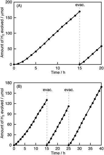
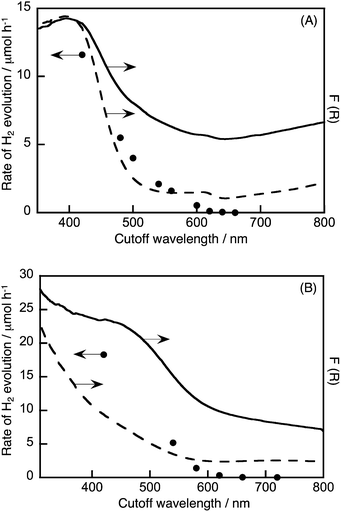
The photocatalytic activities of the materials for hydrogen and oxygen evolution in the presence of sacrificial reagents were evaluated. A Ru cocatalyst that was a stable and effective cocatalyst in the aqueous K2SO3 and Na2S solution,10 rather than Pt, was loaded onto the photocatalysts by an in situ photodeposition method for the sacrificial hydrogen evolution. Although non-treated K2La2Ti3O10 and NaTaO3 were active photocatalysts under UV light irradiation, they showed negligible activity for hydrogen evolution under visible light irradiation, due to no absorption occurring in the visible light region. All of the Cu(I)-substituted photocatalysts produced hydrogen under visible light irradiation, as shown in Table 1. Notably, Ru-loaded Cu(I)–K2La2Ti3O10 and Cu(I)–NaTaO3 showed relatively high activities. None of the Cu(I)-substituted samples produced hydrogen and/or oxygen from pure water under visible light irradiation, indicating that the substituted Cu+ ions were not oxidized and/or reduced by photogenerated electrons and holes. In other words, the substituted Cu+ ions in these samples can remain as Cu+ even in water and under photoirradiation. Fig. 3 shows the time-course of hydrogen evolution from an aqueous solution containing sulfur compounds as sacrificial reagents under visible light irradiation over Ru-loaded Cu(I)–K2La2Ti3O10 or Cu(I)–NaTaO3, with the typical layered and bulk structures, respectively. The photocatalysts steadily evolved hydrogen after an induction period of a few hours, where the Ru cocatalyst was being loaded on the photocatalysts. Turnover numbers of the number of electrons reacted for hydrogen evolution over Cu(I)–K2La2Ti3O10 and Cu(I)–NaTaO3 to the number of substituted Cu+ were 1.7 at 20 h and 13 at 40 h, respectively. The turnover number being larger than the unity indicates that the hydrogen evolution photocatalytically proceeds with negligible oxidation of Cu(I). The apparent quantum yields of the hydrogen evolution over Ru/Cu(I)–K2La2Ti3O10 and Ru/Cu(I)–NaTaO3 from an aqueous solution containing sulfur sacrificial reagents, under monochromatic light irradiation at 420 nm, were both 0.18%. All of the Cu(I)-substituted photocatalysts barely showed activity for oxygen evolution from an aqueous silver nitrate solution, because the potentials of the valence band maxima of these Cu(I)-substituted photocatalysts are similar or more negative than that for water oxidation to oxygen. Fig. 4 shows the wavelength dependence of hydrogen evolution over Ru/Cu(I)–K2La2Ti3O10 or Ru/Cu(I)–NaTaO3. The incident wavelength was controlled with cutoff filters. These photocatalysts responded to visible light up to 620 nm. The higher base lines of the diffuse reflectance spectra were due to the loaded Ru cocatalyst. The onsets of the wavelength dependencies of hydrogen evolution agreed with those of the diffuse reflectance spectra of Ru/Cu(I)–K2La2Ti3O10 and Ru/Cu(I)–NaTaO3. This result indicates that the hydrogen evolution over these photocatalysts proceeded by photoexcitation from valence bands consisting of Cu(I) to the conduction bands. The band gaps and energy gaps were determined from the diffuse reflectance spectra and the wavelength dependencies of the photocatalytic reaction.Conclusions
We have successfully obtained visible light responses from oxide photocatalysts with a wide band gap through using a molten CuCl treatment. A molten CuCl procedure is useful for the development of visible-light-responsive metal oxide photocatalysts because Cu(I)-substituted photocatalysts cannot be prepared using a solid-state reaction. In the layered material K2La2Ti3O10, Cu+ ions were substituted for alkali ions at the interlayer through molten CuCl treatment of the layered photocatalysts, resulting in the band gap narrowing from 3.5 eV to 2.0 eV. In the bulky material NaTaO3, Cu+ ions were substituted for alkali ions near or just at the surface through molten CuCl treatment of the bulky photocatalysts. The substituted Cu+ ions at and/or near the surface contributed to visible light absorption, resulting in the Cu(I)-substituted NaTaO3 possessing an energy gap of 2.0 eV. The Cu(I)-substituted K2La2Ti3O10 and NaTaO3 photocatalysts produced hydrogen steadily by utilizing visible light up to 620 nm, accompanied with photoexcitation from valence bands consisting of Cu(I) to the conduction bands. This band engineering by Cu+ ion substitution will be a promising guide for the design of visible-light-driven photocatalysts.Acknowledgements
This work was supported by a Grant in Aid (no. 24107001 and 24107004) for Science Research on Innovative Areas (Area no. 2406) from the Ministry of Education, Culture, Sports, Science and Technology (MEXT) in Japan.Notes and references
- A. Kudo, H. Kato and I. Tsuji, Chem. Lett., 2004, 33, 1534 CrossRef CAS; A. Kudo and Y. Miseki, Chem. Soc. Rev., 2009, 38, 253 RSC.
- H. Kato, H. Kobayashi and A. Kudo, J. Phys. Chem. B, 2002, 106, 12441 CrossRef CAS.
- Y. Hosogi, K. Tanabe, H. Kato, H. Kobayashi and A. Kudo, Chem. Lett., 2004, 33, 28 CrossRef CAS.
- A. Kudo, K. Omori and H. Kato, J. Am. Chem. Soc., 1999, 121, 11459 CrossRef CAS.
- O. Palasyuk, A. Palasyuk and P. A. Maggard, J. Solid State Chem., 2010, 183, 814 CrossRef CAS PubMed; O. Palasyuk, A. Palasyuk and P. A. Maggard, Inorg. Chem., 2010, 49, 10571 CrossRef PubMed; O. Palasyuk and P. A. Maggard, J. Solid State Chem., 2012, 191, 263 CrossRef PubMed.
- U. A. Joshi, A. M. Palasyuk and P. A. Maggard, J. Phys. Chem. C, 2011, 115, 13534 CAS; L. Fuoco, U. A. Joshi and P. A. Maggard, J. Phys. Chem. C, 2012, 116, 10490 Search PubMed.
- U. A. Joshi and P. A. Maggard, J. Phys. Chem. Lett., 2012, 3, 1577 CrossRef CAS.
- P. P. Sahoo and P. A. Maggard, Inorg. Chem., 2013, 52, 4443 CrossRef CAS PubMed.
- S. Inoue, K. Ueda and H. Hosono, Phys. Rev. B: Condens. Matter Mater. Phys., 2001, 64, 245211 CrossRef.
- I. Tsuji, H. Kato, H. Kobayashi and A. Kudo, J. Phys. Chem. B, 2005, 109, 7323 CrossRef CAS PubMed.
- H. Kato, A. Takeda, M. Kobayashi, M. Hara and M. Kakihana, Catal. Sci. Technol., 2013, 3, 3147 CAS.
- L. Jahnberg, J. Solid State Chem., 1982, 41, 286 CrossRef CAS.
- T. Kimura, in Advances in Ceramics – Synthesis and Characterization, Processing and Specific Applications, ed. C. Sikalidis, INTHCH, Rijeka, 2011, ch. 4, pp. 90–96 Search PubMed.
- Y. Hosogi, H. Kato and A. Kudo, J. Mater. Chem., 2008, 18, 647 RSC.
- K. Domen, A. Kudo, A. Shinozaki, A. Tanaka, K. Maruya and T. Onishi, J. Chem. Soc., Chem. Commun., 1986, 356 RSC.
- K. Domen, J. Yoshimura, T. Sekine, A. Tanaka and T. Onishi, Catal. Lett., 1990, 4, 339 CrossRef CAS.
- T. Mitsuyama, A. Tsutsumi, T. Hata, K. Ikeue and M. Machida, Bull. Chem. Soc. Jpn., 2008, 81, 401 CrossRef CAS.
- H. Kato and A. Kudo, J. Phys. Chem. B, 2001, 105, 4285 CrossRef CAS.
- S. Ikeda, M. Hara, J. N. Kondo, K. Domen, H. Takahashi, T. Okubo and M. Kakihana, Chem. Mater., 1998, 10, 72 CrossRef CAS.
- N. S. Mclntyre and M. G. Cook, Anal. Chem., 1975, 47, 2208 CrossRef; C. D. Wagner, Faraday Discuss. Chem. Soc., 1975, 60, 291 RSC.
- R. Nozaki, J. N. Kondo, C. Hirose, K. Domen, A. Wada and Y. Morioka, J. Phys. Chem. B, 2001, 105, 7950 CrossRef CAS.
Footnote |
| † Electronic supplementary information (ESI) available. See DOI: 10.1039/c4sc01829j |
| This journal is © The Royal Society of Chemistry 2015 |


