 Open Access Article
Exploring the ring current of carbon nanotubes by first-principles calculations
Pengju
Ren†
a,
Anmin
Zheng†
b,
Jianping
Xiao
a,
Xiulian
Pan
a and
Xinhe
Bao
*a
aState Key Laboratory of Catalysis, Dalian Institute of Chemical Physics, Chinese Academy of Sciences, Zhongshan Road 457, Dalian 116023, China. E-mail: xhbao@dicp.ac.cn
bState Key Laboratory of Magnetic Resonance and Atomic and Molecular Physics, Wuhan Center for Magnetic Resonance, Wuhan Institute of Physics and Mathematics, Chinese Academy of Sciences, Wuhan 430071, China
First published on 27th August 2014
Abstract
Ring current is a fundamental concept to understand the nuclear magnetic resonance (NMR) properties and aromaticity for conjugated systems, such as carbon nanotubes (CNTs). Employing the recently developed gauge including projector augmented wave (GIPAW) method, we studied the ring currents of CNTs systematically and visualized their distribution. The ring current patterns are determined by the semiconducting or metallic properties of CNTs. The discrepancy is mainly caused by the axial component of external magnetic fields, whereas the radial component induced ring currents are almost independent of the electronic structures of CNTs, where the intensities of the ring currents are linearly related to the diameters of the CNTs. Although the ring currents induced by the radial component are more intense than those by the axial component, only the latter determines the overall NMR responses and aromaticity of the CNTs as well. Furthermore, the semiconducting CNTs are more aromatic than their metallic counterparts due to the existence of delocalized ring currents on the semiconducting CNTs. These fundamental features are of vital importance for the development of CNT-based nanoelectronics and applications in magnetic fields.
Introduction
The physicochemical properties of molecules confined in carbon nanotubes (CNTs) have attracted great interest in diverse fields, such as drug delivery, nanofluidics, nano-devices, and catalysis.1–3 CNTs consist of sp2 hybridized carbon and can be envisioned as extended conjugated systems, possessing the characteristic behaviors of ring currents, as placed in an external magnetic field.10 The magnetic properties of CNTs and the chemical shifts of CNT-confined molecules can be significantly influenced.11,12 Nuclear magnetic resonance (NMR) spectroscopy is a versatile tool to investigate host–guest systems, by detecting their local electronic structures and the chemical environment of probed nuclei. For example, various molecules e.g. water, methanol and benzene, confined inside the channel of CNTs have been investigated by NMR.4–7 However, the experimental results revealed that the chemical shifts of the CNT-confined molecules are quite different from those confined within other nanosized channels, such as zeolites.8,9 Thus, the chemical shifts of the confined molecules in CNTs remarkably decreased when compared with the shift of the bulk molecule, as observed in a number of experimental procedures.4–7 The nuclei independent chemical shifts (NICSs) offer a convenient route to investigate the magnetic responses shielding of molecules confined in CNT channels.13 With this method, Sebastiani and Kibalchenko et al. interpreted the significant changes in NMR properties of small molecules encapsulated inside CNTs.13,14 The NMR properties for CNT systems are directly related to their electronic structures. The magnetic responses of metallic CNTs are paramagnetic inside the CNT channels, whereas semiconducting CNTs are diamagnetic.13,14 Our previous work demonstrated that the ring currents of CNTs play a critical role in the chemical shift changes.9Besides the effects on NMR response, the analysis of ring current is an efficient way to illustrate the aromaticity of conjugated systems. Aromaticity is an important property for explaining a variety of chemical behaviors, including structural features, energetic stabilities, spectroscopic properties, and reactivity.15,16 The aromaticity of CNTs has been investigated by various methods, but with differing conclusions. For example, Aihara et al. reported that both metallic and semiconducting CNTs have positive resonance energies, and the metallic CNTs are slightly less aromatic than the semiconducting ones.17,18 On the other hand, by correlating the aromaticity with the chemical reactivity of CNTs, it was found that semiconducting nanotubes are analogous to aromatic [4n + 2] annulenes, whereas metallic nanotubes are analogous to antiaromatic [4n] annulenes,19 which explained well the high reactivity of metallic nanotubes over the semiconducting ones.20,21 However, the adaptive natural density partitioning (AdNDP) analysis proved that graphene is locally aromatic with π electrons located over the hexagon rings and no global π delocalization is presented. In addition, Ormsby and King found that only metallic CNTs can be represented by aromatic sextets and hence are more aromatic by using the Clar valence bond (VB) model.22 Their NICS calculations on a series of finite, hydrogen terminated CNTs agreed with the Clar VB model. The aromaticity of CNTs and the correlation with their reactivity is still an open issue at present.23
Although the ring current effect is important for understanding the NMR and aromaticity, it has not been systemically studied. In addition, the complicated topology of CNTs makes the ring current an intricate, rather than a simple, aromatic ring. In this work, with the aid of the recently developed gauge including projector augmented wave (GIPAW) method and the 3D visualization approach, we studied the ring current of CNTs by considering various diameters and electronic structures, intending to trace the origins of the magnetic behaviors of CNTs and their aromatic characters.
Results and discussion
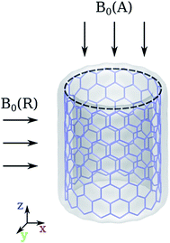
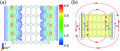
According to the structural index λ = mod(n − m, 3), where (n, m) is the rolling vector, the CNTs can be divided into two families: for CNTs with λ = 0, they are metallic; for CNTs with λ ≠ 0, they are semiconducting. CNTs-(n, 0) with n varying between 10 ∼ 17 were investigated, where CNT-(12, 0) and CNT-(15, 0) are metallic, and others are semiconducting. Due to the tubular morphology of CNTs, their ring currents also depend on the orientation of the CNTs in the magnetic field, B0. There are two characteristic directions of B0 relative to the nanotube axis: B0(R) in the radial direction and B0(A) in the axial direction as illustrated by Fig. 1. First we focus on the ring current induced by B0(R).As shown in Fig. 2a, the intensities of ring currents induced by B0(R) for all CNTs are positive, which indicates that these currents flow anticlockwise and will result in diamagnetic effects. Moreover, the outer ring currents are always more intense than the inner ones. The difference between inner and outer currents by B0(R) seemingly implies the difference of the electronic states between inside and outside the CNTs. It is known that the electron clouds of CNTs are different from a graphene layer, with more electron clouds outside than inside due to the curvature.24,25 However, detailed analysis reveals that it is not the intrinsic reason for the discrepancy between the inner and outer currents. As shown in Fig. 2a, the fitting lines for the inner and outer current are nearly parallel indicating the differences of current intensity are independent on the diameter. Herein, we propose that the weaker inner ring currents are due to the canceling-out effect between delocalized current and the localized current illustrated in Fig. 3b. Both the currents flow anticlockwise, so the outer currents flow in the same direction while the inner currents flow in the opposite direction. As a result, the outer currents are enhanced whereas the inner currents are reduced (Fig. 3a).
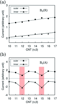 | ||
| Fig. 2 Ring currents Jint(r = 0.7) (a) by B0(R) and (b) by B0(A) for CNT-(n, 0), with n from 10 to 17. Jint(r) is defined in the computational detail part. | ||
In contrast to the ring currents by B0(R), which are almost independent from their electronic structures, the currents by B0(A) typically related to the electronic structure of the CNTs: the currents of metallic CNTs are distinctive from the ones for semiconducting CNTs, as shown in Fig. 2b. The ring current reflects the orbital delocalizability which, in turn, relates to the electronic structure such as the density of states and the orbital topology. The difference of the ring currents reflects the orbital topology of semiconducting and metallic CNTs, which is consistent with the band structure analysis.19
The ring currents show a counter-rotating phenomenon. In other words, the positive outer currents flow anticlockwise, while the negative inner currents flow clockwise. This is similar to the case in coronene,26 which causes a different magnetic effect for the outer ring and inner ring. The counter-rotating currents result in opposite magnetic effects being partially cancelled out.
Compared to the currents by B0(R), the overall currents by the B0(A) are less intense. However, the currents by the B0(A) are more sensitive to the electronic structures of CNTs. Hence, ring currents by B0(A) are responsible for the difference in the chemical shift of 13C in CNTs themselves and the confined molecules between semiconducting and metallic CNTs.9,27,28
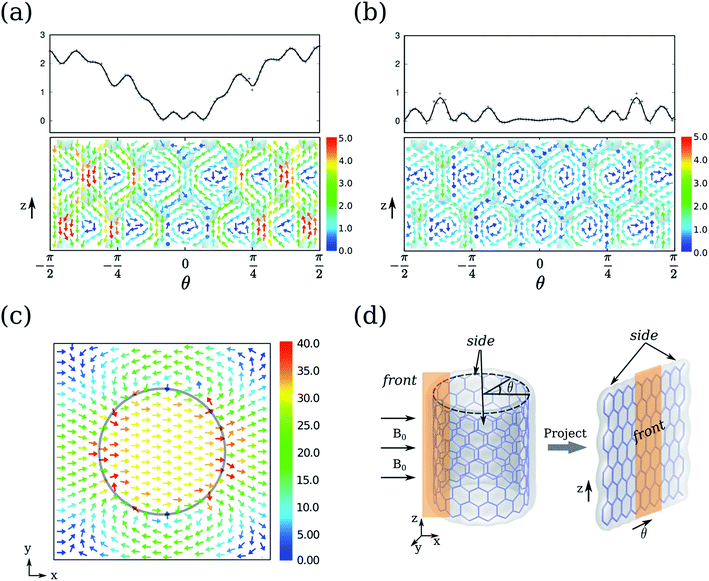
To access the detail picture, we plot the vectorial map of ring currents. Firstly, we focus on the ring currents induced by B0(R). Since they do not depend on the electronic structure of CNTs, the ring currents of CNT-(11, 0) are taken as an example as shown in Fig. 4a and b. The circular ring current on the CNT surface is projected on the plane in Fig. 4d. The outer ring current of CNT-(11, 0) in Fig. 4a shows that the side currents (where θ > π/4 or θ < −π/4) are more intense than the currents in the front (−π/4 < θ < π/4). The positive Jint(θ) indicate the overall current flows anticlockwise. From the vectorial map, the currents on the side flow through the whole backbone of the CNT. Since the periodic model is used in our calculations, the currents do not circulate as a closed loop within a unit cell. In contrast, the front currents are more localized on the six-member-rings. In addition, the CNT-(11, 0) possesses the most intensive currents on the side, where the six-member-rings are parallel to B0. However, it is well known that a benzene molecule perpendicular to B0 always exhibits stronger ring currents. Hence, the ring currents of CNTs cannot be intuitively predicted from a simple aromatic ring.
The ring currents further induce a magnetic field, as shown in Fig. 4c, resulting in a diamagnetic zone in the front and back and a paramagnetic zone in the side of the CNT. This response is qualitatively in line with the classic Ampère's circuital law, where the overall anticlockwise currents will produce a magnetic field opposite to B0. Interestingly, the field vectors inside the CNT are rather uniform both in direction and strength, except that the area is very close to the nanotube wall. On the contrary, the field vectors outside the CNT vary with the distance to the CNT.
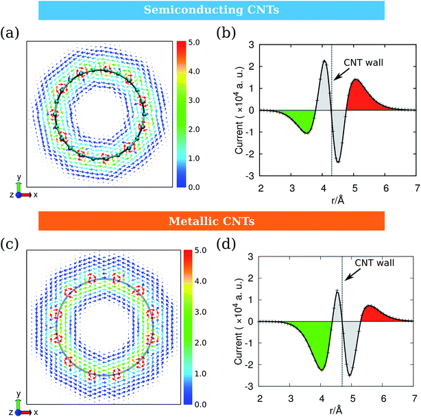
As the ring current induced by B0(A) depends on the electronic structures of CNTs, we take CNT-(11, 0) and CNT-(12, 0) as examples of the semiconducting and metallic CNTs and discuss them separately. Fig. 5 illustrates the ring currents for semiconducting and metallic CNTs. The ring current maps in Fig. 5a and c clearly illustrate the counter-rotating phenomenon. Their radial integrations are shown in Fig. 5b and d, where the currents near the CNT wall are recognized to have contributions from the inner shell σ electrons (grey), while the currents in red and green are from π electrons. As the σ-currents always localize in the area near the nucleus, the delocalized π-currents are more important for the overall magnetic response of CNTs.13Fig. 5b and d indicate that the counter-rotating phenomenon also occurs between σ-currents and π-currents. The difference between Fig. 5b and d is that, for semiconducting CNT-(11, 0), the outer currents are more intense than the inner ones. However, for metallic CNT-(12, 0), the outer currents are weaker than the inner ones. This will result in a very different magnetic response.
The B0(A) induced magnetic field for semiconducting and metallic CNTs are compared in Fig. 6. The counter-rotating currents result in opposite magnetic effects being partially cancelled out. For semiconducting CNTs, as the outer ring currents are slightly more intense than the inner ones, the remaining magnetic response is weak diamagnetism (Fig. 6a). On the contrary, the induced magnetic field for metallic CNTs exhibits a paramagnetic effect due to a more intense clockwise ring current. Furthermore, because of the larger difference between the inner and outer currents in CNT-(12, 0), its induced magnetic field is more intense than CNT-(11, 0). The field vectors inside the CNT are also uniform both in direction and strength, which is similar to the case in Fig. 4c.
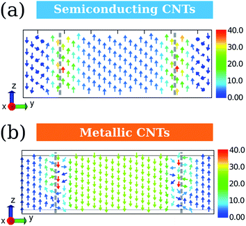 | ||
| Fig. 6 The induced magnetic fields by B0(A) for (a) semiconducting CNT-(11, 0) and (b) metallic CNT-(12, 0). The unit for magnetic field is ×10−6/B0. | ||
Based on the induced magnetic field, we calculated the isotropic nuclear independent chemical shift (iso-NICS). Fig. 7 shows the vertical and horizontal sections of the iso-NICS distributions for CNT-(11, 0) and CNT-(12, 0). Firstly, the inner iso-NICS for CNT-(12, 0) is less intense than the one of CNT-(11, 0). This is due to the paramagnetic response for CNT-(12, 0) by the B0(A). Another interesting phenomenon is that the inner-tube iso-NICS distributions are rather uniform in both the radial and axial direction, which indicates that the magnetic shielding for confined molecules is independent with their location.9 In addition, the outer iso-NICS of CNT-(12, 0) is slightly more intense and dispersed than in the case of CNT-(11, 0), which is due to the larger discrepancy of inner and outer ring current induced by B0(A) for CNT-(12, 0). Therefore, the magnetic responses for CNTs are mostly determined by the ring currents induced by B0(A) instead of B0(R).
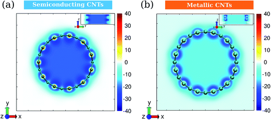 | ||
| Fig. 7 Isotropic NICS distributions (in ppm) for (a) semiconducting CNT-(11, 0) and (b) metallic CNT-(12, 0). The insets are views in the radial direction. The unit of color bars is ppm. | ||
The ring current patterns reflect the aromaticity of CNTs according to the original definition. The anti-clockwise flowing ring current by B0(R) indicates that all kinds of CNTs are aromatic. Moreover, the coexistence of delocalized and localized ring currents illustrates the competition of super-aromaticity and local aromaticity.18 The ring current by B0(R) increases with radius indicating more aromaticity for larger CNTs. On the other hand, the ring current by B0(A) indicates that the semiconducting CNTs are more aromatic than those that are metallic. The isotropic NICS analysis confirms this conclusion where the more diamagnetic effect indicates a more aromatic character. The conclusion derived from ring current agrees well with the evidence that semiconducting CNTs with larger HOMO–LUMO gaps are always more aromatic.29 The advantage of the vectorial map of the ring current is that both the local and delocalized aromatic characters and their competition can be intuitively described.
The classic concept of ring current is nicely extended to CNTs, and it provides a direct and intuitive way to understand the NMR responses and aromaticity of CNTs. It is expected to be applicable for other conjugate supramolecules. The dependence of the CNT electronic structures on the ring current and aromaticity can be used for distinguishing and separating the different types of CNTs. These fundamental insights are crucially important for applications of CNTs.
Conclusion
By employing the GIPAW method, the ring currents of semiconducting and metallic CNTs were investigated. The ring currents strongly depend on the specific direction of the external magnetic fields, B0. For the ring current induced by B0(R), their flowing direction and intensities are not sensitive to the type of CNT, and the intensities are almost linearly related with their diameters. The vectorial map illustrated that the ring current delocalized on the entire CNT rather than localized on the six-member-rings. In addition, the outer currents are more intense than the currents inside the CNT channel. In comparison, the ring currents by B0(A) depend on the electronic structures (semiconducting or metallic) of CNTs and hence determine the overall magnetic responses and the aromatic characters. The semiconducting CNTs are more aromatic compared with the metallic counterparts due to the more delocalized ring currents.Computational details
The calculations were carried out with Quantum ESPRESSO suite,30 using ultrasoft pseudopotentials with Perdew–Burke–Ernzerhof exchange–correlation functional31 and plane-wave basis sets. The plane-wave energy cutoff was set to 37 Ry for structures optimization, and 42 Ry for NMR calculations. The k-point grids were set to 1 × 1 × 4 for structure optimization by using Monkhorst–Pack sampling method.32 Based on convergence tests, the k-point grids for semiconducting and metallic CNTs were set to 1 × 1 × 14 and 1 × 1 × 80 for NMR calculations, respectively. The initial geometries of the CNTs were taken from the optimized structures by Zurek et al.33Ring currents and induced magnetic fields were calculated for each system using the state-of-the-art GIPAW approach,34 which has been widely applied to investigate the NMR parameters of various condensed materials, such as zeolites and graphene-based structures.35 The detail of GIPAW approach can be found in ref. 34 and 35. In brief, the application of external magnetic field B0 to molecules induces an inhomogeneous electron ring current J which is evaluated from the linear response to the perturbation. In order to discuss more conveniently, the J induced by B0(R) in the radial direction was projected on the plane. The vectorial maps of J outside and inside the CNT with a distance of 0.7 Å to the wall of the CNT are shown in Fig. 4a and b. The current at 0.7 Å is considered to be contributed mainly by π electrons. In order to quantitatively analyze the ring current, the current integration Jint(θ) is defined by:
 | (1) |
 | (2) |
![[thin space (1/6-em)]](https://www.rsc.org/images/entities/char_2009.gif) sin(φ) takes a positive value; otherwise, the ring current J flows clockwise (π < φ < 2π), and takes a negative value.
sin(φ) takes a positive value; otherwise, the ring current J flows clockwise (π < φ < 2π), and takes a negative value.
The vectorial maps of J and induced magnetic field were produced using the 3D scientific data visualization code mayavi2.36 The details of the isotropic NICS calculation can be found in our previous work.9
Notes
The authors declare no competing financial interests.Acknowledgements
We acknowledge the financial support from the Natural Science Foundation of China (11079005, 21033009 and 21173215) and the Ministry of Science and Technology of China (2012CB224806 and 2011CBA00503). J. Xiao thanks the financial supports from China Postdoctoral Science Foundation and Outstanding Postdoctoral Award (DMTO Project) from Dalian Institute of Chemical Physics (DICP), Chinese Academy of Science (CAS). We also acknowledge the computational resources from Shanghai Supercomputer Center (SSC).References
- T. A. Hilder and J. M. Hill, Small, 2009, 5, 300–308 CrossRef CAS PubMed.
- T. Zhang, S. Mubeen, N. V. Myung and M. A. Deshusses, Nanotechnology, 2008, 19, 332001 CrossRef PubMed.
- X. Pan and X. Bao, Acc. Chem. Res., 2011, 44, 553–562 CrossRef CAS PubMed.
- H.-J. Wang, X.-K. Xi, A. Kleinhammes and Y. Wu, Science, 2008, 322, 80–83 CrossRef CAS PubMed.
- Q. Chen, J. L. Herberg, G. Mogilevsky, H.-J. Wang, M. Stadermann, J. K. Holt and Y. Wu, Nano Lett., 2008, 8, 1902–1905 CrossRef CAS PubMed.
- X. Liu, X. Pan, W. Shen, P. Ren, X. Han and X. Bao, J. Phys. Chem. C, 2012, 116, 7803–7809 CAS.
- H. Zhang, X. Pan, X. Han, X. Liu, X. Wang, W. Shen and X. Bao, Chem. Sci., 2013, 4, 1075–1078 RSC.
- A. Zheng, B. Han, B. Li, S.-B. Liu and F. Deng, Chem. Commun., 2012, 48, 6936–6938 RSC.
- P. Ren, A. Zheng, X. Pan, X. Han and X. Bao, J. Phys. Chem. C, 2013, 117, 23418–23424 CAS.
- P. Lazzeretti, Prog. Nucl. Magn. Reson. Spectrosc., 2000, 36, 1–88 CrossRef CAS.
- A. C. Forse, J. M. Griffin, V. Presser, Y. Gogotsi and C. P. Grey, J. Phys. Chem. C, 2014, 118, 7508–7514 CAS.
- J. C. Facelli, Magn. Reson. Chem., 2006, 44, 401–408 CrossRef CAS PubMed.
- D. Sebastiani and K. N. Kudin, ACS Nano, 2008, 2, 661–668 CrossRef CAS PubMed.
- M. Kibalchenko, M. C. Payne and J. R. Yates, ACS Nano, 2010, 5, 537–545 CrossRef PubMed.
- R. Islas, T. Heine and G. Merino, Acc. Chem. Res., 2012, 45, 215–228 CrossRef CAS PubMed.
- T. M. Krygowski, H. Szatylowicz, O. A. Stasyuk, J. Dominikowska and M. Palusiak, Chem. Rev., 2014, 114, 6383–6422 CrossRef CAS PubMed.
- J. Aihara, T. Yamabe and H. Hosoya, Synth. Met., 1994, 64, 309–313 CrossRef CAS.
- J. Aihara, J. Phys. Chem., 1994, 98, 9773–9776 CrossRef CAS.
- E. Joselevich, ChemPhysChem, 2004, 5, 619–624 CrossRef CAS PubMed.
- M. S. Strano, C. A. Dyke, M. L. Usrey, P. W. Barone, M. J. Allen, H. Shan, C. Kittrell, R. H. Hauge, J. M. Tour and R. E. Smalley, Science, 2003, 301, 1519–1522 CrossRef CAS PubMed.
- S. Banerjee and S. S. Wong, J. Am. Chem. Soc., 2004, 126, 2073–2081 CrossRef CAS PubMed.
- J. L. Ormsby and B. T. King, J. Org. Chem., 2004, 69, 4287–4291 CrossRef CAS PubMed.
- I. A. Popov, K. V. Bozhenko and A. I. Boldyrev, Nano Res., 2012, 5, 117–123 CrossRef CAS.
- X. Blase, L. X. Benedict, E. L. Shirley and S. G. Louie, Phys. Rev. Lett., 1994, 72, 1878–1881 CrossRef CAS.
- L. Yu, W.-X. Li, X. Pan and X. Bao, J. Phys. Chem. C, 2012, 116, 16461–16466 CAS.
- E. Steiner, P. W. Fowler and L. W. Jenneskens, Angew. Chem., Int. Ed., 2001, 40, 362–366 CrossRef CAS.
- E. Zurek and J. Autschbach, Int. J. Quantum Chem., 2009, 109, 3343–3367 CrossRef CAS.
- C. Engtrakul, V. M. Irurzun, E. L. Gjersing, J. M. Holt, B. A. Larsen, D. E. Resasco and J. L. Blackburn, J. Am. Chem. Soc., 2012, 134, 4850–4856 CrossRef CAS PubMed.
- J. Aihara, J. Phys. Chem. A, 1999, 103, 7487–7495 CrossRef CAS.
- P. Giannozzi, S. Baroni, N. Bonini, M. Calandra, R. Car, C. Cavazzoni, D. Ceresoli, G. L. Chiarotti, M. Cococcioni, I. Dabo, A. Dal Corso, S. de Gironcoli, S. Fabris, G. Fratesi, R. Gebauer, U. Gerstmann, C. Gougoussis, A. Kokalj, M. Lazzeri, L. Martin-Samos, N. Marzari, F. Mauri, R. Mazzarello, S. Paolini, A. Pasquarello, L. Paulatto, C. Sbraccia, S. Scandolo, G. Sclauzero, A. P. Seitsonen, A. Smogunov, P. Umari and R. M. Wentzcovitch, J. Phys.: Condens. Matter, 2009, 21, 395502 CrossRef PubMed.
- J. P. Perdew, K. Burke and M. Ernzerhof, Phys. Rev. Lett., 1996, 77, 3865–3868 CrossRef CAS.
- H. J. Monkhorst and J. D. Pack, Phys. Rev. B: Condens. Matter Mater. Phys., 1976, 13, 5188–5192 CrossRef.
- E. Zurek, C. J. Pickard, B. Walczak and J. Autschbach, J. Phys. Chem. A, 2006, 110, 11995–12004 CrossRef CAS PubMed.
- F. Mauri, B. G. Pfrommer and S. G. Louie, Phys. Rev. Lett., 1996, 77, 5300–5303 CrossRef CAS.
- C. Bonhomme, C. Gervais, F. Babonneau, C. Coelho, F. Pourpoint, T. Azaïs, S. E. Ashbrook, J. M. Griffin, J. R. Yates, F. Mauri and C. J. Pickard, Chem. Rev., 2012, 112, 5733–5779 CrossRef CAS PubMed.
- P. Ramachandran and G. Varoquaux, Comput. Sci. Eng., 2011, 13, 40–51 CrossRef.
Footnote |
| † These authors have contributed equally. |
| This journal is © The Royal Society of Chemistry 2015 |

