 Open Access Article
Creative Commons Attribution 3.0 Unported Licence
Mesoporous inorganic salts with crystal defects: unusual catalysts and catalyst supports†
Xinchen
Kang
a,
Wenting
Shang
a,
Qinggong
Zhu
a,
Jianling
Zhang
a,
Tao
Jiang
*a,
Buxing
Han
*a,
Zhonghua
Wu
b,
Zhihong
Li
b and
Xueqing
Xing
b
aBeijing National Laboratory for Molecular Sciences, Key Laboratory of Colloid and Interface and Thermodynamics, Institute of Chemistry, Chinese Academy of Sciences, Beijing 100190, China. E-mail: jiangt@iccas.ac.cn; hanbx@iccas.ac.cn
bBeijing Synchrotron Radiation Facility, Institute of High Energy Physics, Chinese Academy of Sciences, Beijing 100049, China
First published on 6th January 2015
Abstract
We proposed a strategy to synthesize mesoporous inorganic salt particles using the special properties of ionic liquid (IL) mixtures, and hollow mesoporous LaF3, NdF3, and YF3 particles were synthesized and characterized using different techniques. The size of the mesopores in the salt particles was about 4 nm, and the materials were full of crystal defects. The LaF3, NdF3 and YF3 particles were used as the catalysts for the cyanosilylation reaction of benzaldehyde using trimethylsilyl cyanide, and Ru/LaF3 and Ru/NdF3, in which Ru nanocatalysts were supported on the LaF3 and NdF3 particles with mesopores, were used to catalyze hydrogenations of benzene to cyclohexane and levulinic acid (LA) to γ-valerolactone (GVL). It was discovered that the activities of these catalysts were unprecedentedly high for these reactions. Detailed study showed that both the crystal defects and the mesopores in the salt particles played crucial roles for the extremely high catalytic activity.
Introduction
Porous materials have wide-ranging applications due to their admirable and intriguing structures. Common porous materials include porous carbon materials,1 porous polymers,2 zeolite materials,3 metal–organic frameworks (MOFs),4 and covalent organic frameworks (COFs),5 and so on. Porous materials have a variety of applications or potential applications, such as catalysis,6 gas separation, capture and storage,7 and electrode materials.8 Inorganic salts are composed of cations and anions of small size. The strong interaction among the ions leads to a close-packed structure of the salts, which is more feasible to form a perfect crystal. The reports about preparation of porous salts are very limited. Cong et al. synthesized NaCl and KCl with macropores (380 nm in diameter) using copolymer colloids as the template.9 Chu et al. prepared porous FeF3 particles consisting of small nanoparticles through two steps: Fe(OH)3 synthesis and FeF3 fabrication.10Ionic liquids (ILs) have received much interest due to their special properties such as negligible vapor pressure, good thermal stability, high conductivity, and strong solvent power for both organic and inorganic substances.11 Especially, ILs have a designable nature.12 These unique properties make them have great potential in applications in different fields, such as material synthesis,13 chemical reactions,14 extraction and fractionation,15 and gas absorption.16
Catalysis is quite prevalent in chemical reactions and chemical industry.17 Supported metal catalysts are widely used because the metal components are active for various reactions.18 It is well known that for supported catalysts, catalyst supports often have great influence on the activity, selectivity, and stability of the catalysts.19 Mesoporous inorganic salt particles may have many advantages in catalysis which are not known because their synthesis is challenging.
Herein, we proposed a strategy to synthesize porous inorganic salts using IL–organic salt mixtures. LaF3, NdF3, and YF3 particles with mesopores were successfully synthesized. As examples of applications, the mesoporous salt particles were used both as the catalysts directly and supports of Ru nanocatalysts. It was discovered that the salts and the salt supported catalysts exhibited unprecedented activity for different reactions. Systematic study indicated that both the crystal defects and mesopores contributed significantly to the very high catalytic activity. To the best our knowledge, this is the first work to use mesoporous inorganic salts as catalysts and catalyst supports.
Results and discussion
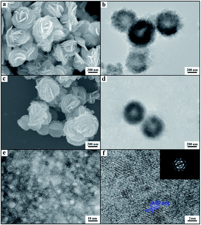
We synthesized the inorganic salts in tetrabutylammonium hexafluorophosphate (N(Bu)4PF6) and IL 1-octyl-3-methylimidazolium chloride (OmimCl) mixtures. N(Bu)4PF6 is an organic salt with a melting point of 246–247 °C.20 OmimCl is liquid at room temperature. Fig. S1† shows the solubility of N(Bu)4PF6 (x2, in mole fraction) in OmimCl determined in this work. The solubility of N(Bu)4PF6 in OmimCl decreases with decreasing temperature. Therefore, some N(Bu)4PF6 will precipitate as its content in the OmimCl–N(Bu)4PF6 mixture exceeds the solubility (Fig. S1†).We synthesized LaF3 in OmimCl–N(Bu)4PF6 mixtures at x2 (mole fraction of N(Bu)4PF6 in OmimCl–N(Bu)4PF6 mixture) of 0.50 and 0.33 using La(NO3)3 as the metal precursor. Some precipitated N(Bu)4PF6 particles existed in the OmimCl–N(Bu)4PF6 mixtures at these conditions. The LaF3 was generated from La(NO3)3 and N(Bu)4PF6, and the reaction equation is shown in Scheme S1.†21 The X-ray diffraction (XRD) patterns of the as-prepared materials demonstrate clearly the formation of LaF3 (Fig. 1). The half-peak width in the XRD patterns was much larger than the commercial LaF3 (Fig. 1), indicating the poor crystallinity and existence of significant amounts of crystal defects in the LaF3 prepared in this work. The scanning electron microscopy (SEM) and transmission electron microscopy (TEM) images of the LaF3 materials are given in Fig. 2. The size of the mesopores in the particles was about 4 nm (Fig. 2e), which are intracrystal pores. The size of the particles was about 400 nm and each particle had a hollow core of about 80 nm.
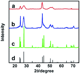 | ||
| Fig. 1 XRD patterns of LaF3: (a) LaF3 synthesized at x2 = 0.5; (b) LaF3 synthesized at x2 = 0.33; (c) commercial LaF3; and (d) standard pattern. | ||
The porous LaF3 particles prepared were further characterized using the N2 adsorption/desorption method, and the adsorption/desorption isotherms and the pore size distributions of the LaF3 particles are given in Fig. 3. The pore size distribution curve of the LaF3 particles prepared had two peaks, which centered at about 4 nm and 55 nm, corresponding to the mesopores in the walls and hollow cores of the particles, respectively. The size of the pores determined by the N2 adsorption/desorption method was roughly consistent with that observed from the TEM images (Fig. 2). The surface areas obtained from the BET (Brunauer, Emmett, and Teller) method and the pore volumes calculated from the Barrett–Joyner–Halenda method are presented in Table 1. The results further demonstrated the mesoporous character.
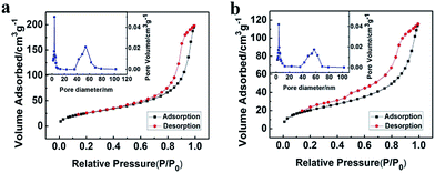 | ||
| Fig. 3 N2 adsorption/desorption isotherms and pore size distribution (the insets) of the LaF3 particles synthesized at x2 = 0.5 (a) and 0.33 (b). | ||
| Entry | Samples | S (m2 g−1) | V (cm3 g−1) |
|---|---|---|---|
| a Porous LaF3 synthesized at x2 = 0.5 (Fig. 2a and b). b Porous LaF3 synthesized at x2 = 0.33 (Fig. 2c and d). c Porous LaF3 synthesized at x2 = 0.17 (Fig. S3a and b). d Porous NdF3 synthesized at x2 = 0.5 (Fig. 8a and b). e Porous YF3 synthesized at x2 = 0.5 (Fig. 8c and d). f Commercial LaF3 (Fig. S4a and b). g La-MOF prepared in this work (Fig. S4c and d). | |||
| 1 | LaF3a | 97.9 | 0.32 |
| 2 | LaF3b | 77.6 | 0.26 |
| 3 | LaF3c | 59.1 | 0.16 |
| 4 | NdF3d | 98.7 | 0.34 |
| 5 | YF3e | 95.7 | 0.28 |
| 6 | LaF3f | 0.48 | 0.002 |
| 7 | La-MOFg | 28.5 | 0.05 |
The compactness of the materials can be characterized by the small angle X-ray scattering (SAXS) technique via analyzing the fractal dimension D.22 In this work we conducted a SAXS study (Fig. 4). According to the SAXS data, it can be known that the mass fractal existed in the LaF3 materials, indicating that the materials had a loose structure with lots of crystal defects,22 which agrees with the fact that the salt particles had poor crystallinity as shown by the XRD patterns (Fig. 1). Moreover, the LaF3 synthesized had plenty of micropores ranging from 0.5 nm to 2 nm, and the pore size distribution is shown in Fig. S2.† The surface area of the micropores was 1.0 m2 g−1, which further confirms the existence of crystal defects in the LaF3 materials. The crystal defects in the LaF3 materials originate mainly from the mesopores, edges, and tips in the salts.
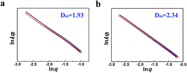 | ||
| Fig. 4 Mass fractal dimension (Dm) from SAXS curves of the as-prepared LaF3 materials synthesized at x2 = 0.5 (a), 0.33 (b). | ||
In order to study the reason for the formation of the hollow cores and mesopores in the LaF3 particles synthesized, we studied the size and shape of the precipitated N(Bu)4PF6 particles in the OmimCl–N(Bu)4PF6 mixtures using the SAXS technique, which is commonly used for characterizing the size and shape of particles dispersed in liquids.23 The SAXS curves of the mixtures with different compositions are presented in Fig. 5a. The data in the small-angle region (q < 1) were used to obtain the size of the precipitated N(Bu)4PF6 particles. The generalized indirect Fourier transformation gives the pair-distance distribution function, p(r), which is shown in Fig. 5b. The curves were nearly symmetric, suggesting that the precipitated N(Bu)4PF6 particles in the OmimCl–N(Bu)4PF6 mixtures were spherical.23 The size of the N(Bu)4PF6 particles calculated from the SAXS data agreed roughly with that of the hollow cores of the LaF3 particles shown in Fig. 2. SAXS is also a useful technique to study the microstructure of ILs. It has highlighted the existence of the nano-scale aggregates, and the size can be estimated using Bragg's diffraction law d = 2π/q.24 The size of the IL aggregates calculated using this method was 3 nm. These could act as the templates to form the mesopores of the LaF3 particles.
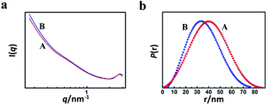 | ||
| Fig. 5 SAXS curves (a) and normalized pair-distance distribution function curves (b) of the OmimCl–N(Bu)4PF6 mixtures at x2 = 0.5 (A) and 0.33 (B). | ||
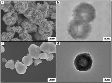
On the basis of the experimental results we can discuss the formation processes of the mesoporous particles, which are shown schematically in Fig. 6. In the OmimCl–N(Bu)4PF6 mixtures, some N(Bu)4PF6 exists as the precipitated particles at x2 = 0.5 and 0.33, and the rest of the N(Bu)4PF6 is dissolved in the solution, as discussed above. The La(NO3)3 reacts with the N(Bu)4PF6 particles at the surface to generate LaF3. At the same time, the La(NO3)3 also reacts with the N(Bu)4PF6 in the solution. The LaF3 generated in the solution aggregates with the LaF3 nanocrystals on the surface of the N(Bu)4PF6 particles. Some IL aggregates are entrained when the LaF3 particles aggregate around the N(Bu)4PF6 particles. The regular hollow LaF3 particles with mesopores are formed after removing the OmimCl and N(Bu)4PF6 by washing with acetone. In this process, the N(Bu)4PF6 particles and the entrained IL aggregates act as the templates for the core and the mesopores, respectively (Fig. 2 and 6). In order to get the evidence that the N(Bu)4PF6 particles act as the template for the formation of the hollow core, we also synthesized the LaF3 particles in the OmimCl–N(Bu)4PF6 mixture at x2 = 0.17, and the SEM and TEM images, XRD patterns, and N2 adsorption/desorption isotherms are given in Fig. S3.† In this case, all the N(Bu)4PF6 dissolves in OmimCl (Fig. S1†). La(NO3)3 reacts with the N(Bu)4PF6 in the solution due to the absence of the precipitated N(Bu)4PF6 particles, and the generated LaF3 aggregates arbitrarily and irregular LaF3 particles are formed (Fig. S3†). The particles with mesopores were also obtained after removing the entrained OmimCl and N(Bu)4PF6, but there was no hollow core (Fig. S3†). The results support the argument that the precipitated N(Bu)4PF6 particles act as the template for the formation of the hollow core of the salt particles at higher N(Bu)4PF6 concentrations (x2 = 0.5 and 0.33).
 | ||
| Fig. 6 The schematic diagram for the formation mechanism of mesoporous LaF3 particles with a hollow core. | ||
We also synthesized NdF3 and YF3 particles in the OmimCl–N(Bu)4PF6 mixture of x2 = 0.50 using this method. The XRD patterns, SEM and TEM images are given in Fig. 7 and 8, respectively. The porosity properties determined using the N2 adsorption/desorption method are given in Table 1. The XRD patterns confirmed the formation of NdF3 and YF3 (Fig. 7). All the characterizations indicate that the morphology, structure, and porosity properties of the NdF3 and YF3 particles were similar to those of LaF3 prepared, which indicates that the strategy proposed in this work is versatile.
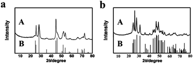 | ||
| Fig. 7 XRD patterns of the as-synthesized fluoride salts (A) synthesized at x2 = 0.5 and the corresponding standard patterns (B): (a) NdF3; and (b) YF3. | ||
The mesoporous salt particles may find wide-ranging applications in different fields. They are very stable inorganic salts and are not soluble in water and common organic solvents, which are excellent characteristics of heterogeneous catalysts and catalyst supports. As examples of applications, we used the salt particles both as a catalyst directly and as the support of metal nanocatalysts for different reactions.
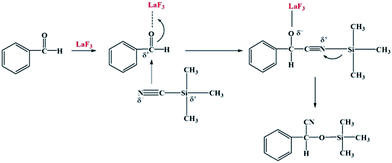
Cyanosilylation of carbonyl compounds provides a convenient route to produce cyanohydrins,25 which are key intermediates in the synthesis of fine chemicals and pharmaceuticals.26 The mesoporous LaF3 shown in Fig. 2a and b was used as a heterogeneous catalyst in the cyanosilylation reaction of benzaldehyde and trimethylsilyl cyanide (TMSCN) to produce cyanohydrin, and the results are given in Table 2. Surprisingly, the LaF3 particles with mesopores were extremely active and selective for the reaction (entry 1). In addition, the mesoporous NdF3 (Fig. 8a and b) and YF3 (Fig. 8c and d) had similar activity for this reaction (entries 2–3). We also studied the activity of commercial LaF3 for this reaction (entry 4), and the activity was much lower (Fig. S4a and b† and Table 1). It has been reported that La metal–organic framework (La-MOF) was an efficient catalyst for this reaction.27 In this work, we synthesized the La-BTC MOF (La-MOF hereafter). The as-prepared La-MOF was characterized by SEM and TEM (Fig. S4c and d†), XRD (Fig. S5†), and N2 adsorption/desorption (Table 1) methods. The XRD pattern was the same as that reported previously.28 The La-MOF was also used to catalyze the reaction, and it was demonstrated that the activity of the mesoporous LaF3 particles was much higher than the La-MOF (entries 1 and 5) for the reaction. In order to study the effect of the defects in the mesoporous LaF3, NdF3 and YF3 particles on the reaction, we calculated the turnover frequencies (TOFs) per unit surface area of all the catalysts in Table 2, which were calculated from the reaction data in Table 2 and the surface area data in Table 1. Surprisingly, the TOFs per unit surface area of the as-prepared mesoporous LaF3, NdF3 and YF3 were much higher than the commercial LaF3 that had no pores, and the La-MOF. It is well known that the mass transfer in mesopores is poorer than that at the surface of nonporous materials. Therefore, it can be concluded that the crystal defects of the mesoporous LaF3, NdF3 and YF3 contributed significantly to their extremely high activity. The reaction mechanism is shown in Scheme 1. The reaction is catalyzed by Lewis acid.27 The crystal defects result in Lewis acid sites,29 which enhances the acidity and is favourable for accelerating the reaction. The commercial LaF3 has limited Lewis acid sites due to the high crystallinity. Thus, both the mesopores and the crystal defects in the salt particles played crucial roles for the very high catalytic activity.
| Entry | Catalysts | t (min) | C (%) | TOF1b (h−1) | TOF2c (g h−1 m−2) |
|---|---|---|---|---|---|
a Reaction conditions: 2 mL benzaldehyde, 5 mol% catalyst, benzaldehyde![[thin space (1/6-em)]](https://www.rsc.org/images/entities/char_2009.gif) : :![[thin space (1/6-em)]](https://www.rsc.org/images/entities/char_2009.gif) TMSCN molar ratio of 1 TMSCN molar ratio of 1![[thin space (1/6-em)]](https://www.rsc.org/images/entities/char_2009.gif) : :![[thin space (1/6-em)]](https://www.rsc.org/images/entities/char_2009.gif) 1.5, 50 °C, solvent free.
b TOF1 is the turnover frequency, which was calculated as moles of converted benzaldehyde per mole of catalyst per hour.
c TOF2 is the turnover frequency, which was calculated as moles of converted benzaldehyde per mole of catalyst per hour per unit area, and surface area data determined in this work (Table 1) were used in the calculation.
d Porous LaF3 (Fig. 2a and b).
e Porous NdF3 (Fig. 8a and b).
f Porous YF3 (Fig. 8c and d).
g Commercial LaF3 (Fig. S4a and b).
h La-MOF prepared in this work (Fig. S4c and d). The quantitative analysis of the product was carried out using GC.
i
C = conversion of benzaldehyde. 1.5, 50 °C, solvent free.
b TOF1 is the turnover frequency, which was calculated as moles of converted benzaldehyde per mole of catalyst per hour.
c TOF2 is the turnover frequency, which was calculated as moles of converted benzaldehyde per mole of catalyst per hour per unit area, and surface area data determined in this work (Table 1) were used in the calculation.
d Porous LaF3 (Fig. 2a and b).
e Porous NdF3 (Fig. 8a and b).
f Porous YF3 (Fig. 8c and d).
g Commercial LaF3 (Fig. S4a and b).
h La-MOF prepared in this work (Fig. S4c and d). The quantitative analysis of the product was carried out using GC.
i
C = conversion of benzaldehyde.
|
|||||
| 1 | LaF3d | 1 | 100 | 1200 | 12.3 |
| 2 | NdF3e | 1 | 100 | 1200 | 12.2 |
| 3 | YF3f | 1 | 100 | 1200 | 12.5 |
| 4 | LaF3g | 10 | 2.2 | 2.6 | 5.4 |
| 5 | La-MOFh | 10 | 6.4 | 7.7 | 0.27 |
We also used the mesoporous LaF3 and NdF3 particles (Fig. 2a and b and 8a and b) as catalyst supports. The Ru/LaF3 and Ru/NdF3 were synthesized using water as the solvent, RuCl3 as the precursor, and NaBH4 as the reductant. The loading of Ru in the catalysts was 1.0 wt% as determined using the ICP-AES (VISTA-MPX) method. The TEM image of the Ru/LaF3 and the size distribution of the Ru particles are shown in Fig. S6.† The Ru nanoparticles of about 1.2 nm were immobilized uniformly on the supports. The Ru nanoparticles in the Ru/NdF3 had a similar size and size distribution.
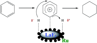
Benzene hydrogenation to cyclohexane is a very important reaction in chemical industry.30 We conducted the reaction using the Ru/LaF3, Ru/NdF3, and commercial Ru/C (TEM and SEM images are given in Fig. S6b and c†) as the catalysts at the same conditions, and the results are shown in Table 3. The catalytic activity of the Ru/LaF3 and Ru/NdF3 was amazingly high compared with that of the commercial Ru/C. It is obvious that the mesoporous morphology of the LaF3 and NdF3 particles played an important role in the reaction. It has also been reported that Lewis acids can activate aromatic rings.31 LaF3 and NdF3, which are Lewis acids, activated the benzene ring and the Ru nanoparticles activated the H2, which made the reaction more feasible to take place (Scheme 2). The crystal defects in the LaF3 and NdF3 lead to the existence of partial charge, which enhances the Lewis acidity and therefore the crystal defects can promote the reaction. The reusability of the Ru/LaF3 catalyst was also studied. It was shown that the catalyst could be reused at least five times without reducing the activity, as shown in Fig. 9.
| Entry | Catalysts | t (h) | T (°C) | Y (%) | TOFb (h−1) |
|---|---|---|---|---|---|
| a Reaction conditions: 2 mL benzene, benzene/Ru (mol mol−1) = 2500, 4 MPa H2. b TOF was calculated as moles of converted benzene per mole of Ru per hour. c Porous LaF3 (Fig. 2a and b) as support. d Porous NdF3 (Fig. 8a and b) as support. e The commercial Ru/C catalyst (Fig. S6b and c). The quantitative analysis of the product was carried out using GC. f Y = yield of cyclohexane. | |||||
| 1 | Ru/LaF3c | 0.22 | 50 | >99 | 11![[thin space (1/6-em)]](https://www.rsc.org/images/entities/char_2009.gif) 364 364 |
| 2 | Ru/LaF3c | 0.77 | 25 | >99 | 3247 |
| 3 | Ru/NdF3d | 0.33 | 50 | >99 | 7576 |
| 4 | Ru/Ce | 8 | 50 | 95.5 | 298 |
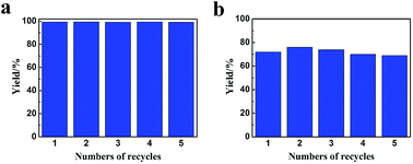 | ||
| Fig. 9 The reusability of the Ru/LaF3 catalyst for benzene hydrogenation to cyclohexane at 50 °C, 0.22 h (a) and 25 °C, 0.5 h (b). The other conditions were the same as in Table 1. | ||
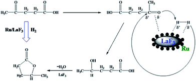
LA hydrogenation to GVL is an important reaction in biomass utilization, and Ru is a very efficient catalyst for the reaction.32 In this work, we carried out the reaction catalyzed by the Ru/LaF3 prepared in this work and commercial Ru/C catalyst under solvent-free conditions, and the results are listed in Table 4. The dependence of the conversion on reaction time at some typical conditions is shown in Fig. S7.† The Ru/LaF3 had much higher activity than the commercial Ru/C and the supported Ru nanocatalysts reported by other researchers. The LaF3 interacts strongly with the carbonyl group by the Lewis acid–base interaction, which may be favourable to the reaction. In addition, an esterification reaction is feasible under acid and alkali conditions and the LaF3 as a Lewis acid can promote the esterification process. Therefore, the special morphology and structure, Lewis acid nature, and enhanced Lewis acidity by the defects of the LaF3 support are the main reasons for the extremely high activity and selectivity of the Ru/LaF3 catalyst for the reaction (Scheme 3).33
| Entry | Catalysts | T (°C) | t (h) | C (%) | S (%) | TOFb (h−1) |
|---|---|---|---|---|---|---|
| a Reaction conditions: 2 mL LA, LA/Ru (mol mol−1) = 2000, initial pressure of H2 was 6 MPa, solvent free. b TOF was calculated as moles of converted LA per mole of Ru per hour. c Porous LaF3 (Fig. 2a and b) as support. d The commercial Ru/C catalyst (Fig. S6b and c). e The catalyst reported in ref. 32. The quantitative analysis of the product was carried out by GC. f C = conversion of LA, S = selectivity of GVL. | ||||||
| 1 | Ru/LaF3c | 130 | 0.5 | >99 | >99 | 4000 |
| 2 | Ru/LaF3c | 100 | 1.25 | >99 | >99 | 1600 |
| 3 | Ru/LaF3c | 70 | 3.5 | >99 | >99 | 571 |
| 4 | Ru/LaF3c | 40 | 9 | >99 | >99 | 222 |
| 5 | Ru/Cd | 130 | 7 | >99 | >99 | 286 |
| 6 | Ru/Cd | 100 | 18 | >99 | >99 | 111 |
| 7 | Ru/Al2O3e | 70 | 3 | 24 | 96 | 137 |
Conclusions
In summary, a protocol to synthesize mesoporous inorganic salts was proposed in this work, and mesoporous LaF3, NdF3 and YF3 were prepared successfully and were full of crystal defects. The catalytic activity of the mesoporous LaF3, NdF3 and YF3 particles could be more than 800 times higher than that of the commercial LaF3 without pores for the cyanosilylation reaction of benzaldehyde using trimethylsilyl cyanide. The catalytic activity of the supported catalysts Ru/LaF3 and Ru/NdF3, in which Ru nanocatalysts were supported on the mesoporous salt particles, was also extremely high for the hydrogenations of benzene to cyclohexane and LA to GVL. The abundant crystal defects in the mesoporous salt particles contributed significantly to the excellent catalytic performance of the catalysts. We believe that this method can also be used to fabricate some other mesoporous inorganic salts, which may have unique features in catalysis, extraction and fractionation, gas absorption, and other fields.Experimental
Materials
OmimCl (purity > 99%) and N(Bu)4PF6 (purity > 99%) were purchased from the Centre of Green Chemistry and Catalysis, LICP, CAS. LaF3 (purity > 99.99%), La(NO3)3·6H2O (A. R. grade), Nd(NO3)3·6H2O (A. R. grade), Y(NO3)3·6H2O (A. R. grade), RuCl3·3H2O (Ru ≥ 37%), benzene (A. R. grade), ethanol (A. R. grade), cyclohexane (A. R. grade), toluene (A. R. grade), and n-butyl alcohol (A. R. grade) were provided by Sinopharm Chemical Reagent Co., Ltd. Benzaldehyde (purity > 98%), trimethylsilyl cyanide (purity > 97%), H3BTC (purity > 99%), LA (purity > 99%) and GVL (purity > 99%) were obtained from J & K Scientific Ltd. NaBH4 (purity ≥ 98%) was provided by Alfa Aesar China (Tianjin) Co., Ltd. The commercial Ru/C catalyst was purchased from Baoji Ruike Corporation, China.The solubility of N(Bu)4PF6 in OmimCl
In the experiment, known amounts of N(Bu)4PF6 and OmimCl were mixed in a glass tube with an inner diameter of 10 mm, which were immersed in an oil bath of desired temperature. The total mass of the mixture was 5.0 g. The mixture was heated to 160 °C to obtain a homogeneous solution. Then the temperature was decreased slowly until the solution became cloudy, indicating that N(Bu)4PF6 began to precipitate. At this temperature, the mixture became clear again as the temperature was increased. The process was repeated five times to determine the saturation temperature.SAXS study
The apparatus and the procedures were similar to that used to study the microstructure of IL gels.13b SAXS experiments were carried out at Beamline 1W2A at the Beijing Synchrotron Radiation Facility. The data were collected using a CCD detector (MAR) with a maximum resolution of 3450 × 3450 pixels. The wavelength of the X-ray was 1.54 Å, and the distance of the sample to detector was 1.596 m. For OmimCl/N(Bu)4PF6 samples, desired amounts of OmimCl and N(Bu)4PF6 were mixed in a glass tube at 160 °C to obtain a homogeneous solution. Then the glass tube was cooled to 85 °C. In a typical experiment, some sample was added into the sample cell with a heating unit around the cell, and the X-ray scattering data were recorded. For the LaF3 samples, the sample was smeared on the sample cell at room temperature, and the other procedures were similar. The 2-D SAXS images were obtained from the detector and then transformed into the profiles of intensity (I) vs. wavevector (q) using the software SAXS Data Pre-process V2.0.0. The pair-distance distribution function p(r) was obtained from SAXS data by using an Irena tool suite within the Igor pro and Gnom application software. The fractal dimension D of LaF3 materials was calculated and analyzed using the method reported.22Synthesis of the porous salt particles
We describe mainly the procedures to synthesize LaF3 because those to synthesize NdF3 and YF3 were similar. In a typical experiment, desired amounts of OmimCl and N(Bu)4PF6 were mixed in a conical flask of 50 mL at 160 °C until the mixture became a homogeneous solution. The total mass of the mixture was 18 g. Then 1.5 mmol of La(NO3)3 was added to the system under vigorous stirring, and then the mixture was cooled to 85 °C in 10 min. The system was maintained at this temperature for 72 h. The obtained mixture containing the materials was mixed with 50 mL acetone and then centrifuged with a centrifugal speed of 5000 rpm. The obtained LaF3 was washed with acetone 10 times and dried in a vacuum oven at 40 °C for 24 h. To synthesize NdF3 or YF3, the procedures were the same. The main difference was that Nd(NO3)3 or Y(NO3)3 were used, instead of La(NO3)3.Synthesis of the La-MOF
The procedure for synthesizing the La-MOF was similar to that used previously.28 In the experiments, 18 g of OmimCl and water were mixed in a conical flask of 50 mL, and the molar fraction of water in the solution was 0.5. Then 1.5 mmol of La(NO3)3·nH2O and 1.5 mmol H3BTC were added to the conical flask. The system was maintained at 85 °C for 72 h under stirring. The obtained mixture containing the materials was centrifuged with a centrifugal speed of 5000 rpm. The obtained La-MOF was washed with acetone 10 times and dried in a vacuum oven at 40 °C for 24 h.Ru/LaF3 and Ru/NdF3 synthesis
We describe the procedure to synthesize Ru/LaF3 because that for the synthesis of Ru/NdF3 was similar. In a typical experiment, 20 mL RuCl3 aqueous solution (1 mmol) was added into a 50 mL flask. Then 0.2 g LaF3 was introduced into the flask and dispersed by ultrasound. The solution was stirred for 0.5 h. Then, 10 mL NaBH4 aqueous solution (20 mmol) was added into the mixture slowly until the Ru3+ was completely reduced. The Ru/LaF3 was washed with water five times and dried at 40 °C for 24 h under vacuum.Characterization
X-Ray diffraction (XRD) analysis of the samples was performed on an X-ray diffractometer (Model D/MAX2500, Rigaka) with Cu-Kα radiation, and the scan speed was 5° min−1. The morphologies of the products were characterized using a HITACHI S-4800 scanning electron microscope (SEM) and a JEOL-1010 transmission electron microscope operated at 100 kV. The crystal structure and SAED pattern were characterized using a TEM JEOL-2100F. The porosity properties of the materials were obtained from nitrogen adsorption–desorption isotherms using a Micromeritics ASAP 2020M system, and then calculated from the Barrett–Joyner–Halenda method. The Ru loading in the Ru/LaF3 catalyst and Ru/NdF3 was determined using the ICP-AES method (VISTA-MPX).Cyanosilylation of benzaldehyde
To carry out the reaction, 2 mL benzaldehyde and a certain amount of LaF3 were placed into a 25 mL glass vial, which was immersed in a constant-temperature water bath of 50 °C. The mixture was stirred (800 rpm) under a N2 atmosphere, and then TMSCN (another reactant) was added and the reaction began.27 After a suitable reaction time, the reaction mixture was centrifuged to precipitate the LaF3 particles. The reaction mixture was analyzed using a gas chromatograph (GC, HP 4890) equipped with a flame ionization detector (FID), and toluene was used as the internal standard. The identification of the products and reactants was done using a GC-MS (SHIMADZU-QP2010) and the 1H NMR spectra were recorded on a Bruker Avance III 400 HD spectrometer in CDCl3 with TMS as an internal standard, as well as by comparing the retention times to respective standards in GC traces.Benzene hydrogenation
The solvent free hydrogenation of benzene to cyclohexane was carried out in a 20 mL stainless steel batch reactor, which was similar to that used previously.31b In the experiment, 2 mL benzene and a desired amount of catalyst were added into the reactor. The reactor was immersed in a water bath of desired temperature, and the reaction was started. Then H2 was introduced into the system at 4 MPa and the pressure was maintained during the reaction. The reaction mixture was cooled in ice-water and H2 was released after 10 minutes. The procedures for products analysis were similar to those described above. In the reuse experiments, the catalyst was washed with ethanol (3 × 5 mL) and was used for the next run after drying at 40 °C under vacuum.LA hydrogenation
The solvent free hydrogenation of LA to GVL was carried out in a 20 mL stainless steel batch reactor, which was the same as that for the hydrogenation of benzene described above. In the experiment, 2 mL LA and a certain amount of catalyst were added into the reactor. The reactor was immersed in an oil bath of desired temperature. Then H2 was introduced into the system at 6 MPa and the stirrer was started. The reaction mixture was cooled in ice-water for 10 minutes and H2 was released. The procedures for product analysis were similar to those described above. Differently, the internal standard for this reaction was n-butyl alcohol.Acknowledgements
The authors thank the National Natural Science Foundation of China (21133009, U1232203, 21321063), Chinese Academy of Sciences (KJCX2.YW.H30).Notes and references
- (a) L. Qie, W. M. Chen, Z. H. Wang, Q. G. Shao, X. Li, L. X. Yuan, X. L. Hu, W. X. Zhang and Y. H. Huang, Adv. Mater., 2012, 24, 2047 CrossRef PubMed; (b) J. Liang, R. F. Zhou, X. M. Chen, Y. H. Tang and S. Z. Qiao, Adv. Mater., 2014, 26, 6074 CrossRef CAS PubMed.
- (a) W. G. Lu, D. Q. Yuan, J. Sculley, D. Zhao, R. Krishna and H. C. Zhou, J. Am. Chem. Soc., 2011, 133, 18126 CrossRef CAS PubMed; (b) D. W. Johnson, C. Sherborne, M. P. Didsbury, C. Pateman, N. R. Cameron and F. Claeyssens, Adv. Mater., 2013, 25, 3178 CrossRef CAS PubMed.
- (a) Z. P. Wang, J. H. Yu and R. R. Xu, Chem. Soc. Rev., 2012, 41, 1729 RSC; (b) L. L. Zhang, Z. Q. Hu and J. W. Jiang, J. Am. Chem. Soc., 2013, 135, 3722 CrossRef CAS PubMed; (c) Q. Wen, J. C. Di, L. Jiang, J. H. Yu and R. R. Xu, Chem. Sci., 2013, 4, 591 RSC.
- (a) T. R. Cook, Y. R. Zheng and P. J. Stang, Chem. Rev., 2013, 113, 734 CrossRef CAS PubMed; (b) S. Cao, G. Gody, W. Zhao, S. Perrier, X. Y. Peng, C. Ducati, D. Y. Zhao and A. K. Cheetham, Chem. Sci., 2013, 4, 3573 RSC; (c) M. Li, D. Li, M. O'Keeffe and O. M. Yaghi, Chem. Rev., 2014, 114, 1343 CrossRef CAS PubMed.
- (a) T. Tozawa, J. T. A. Jones, S. I. Swamy, S. Jiang, D. J. Adams, S. Shakespeare, R. Clowes, D. Bradshaw, T. Hasell, S. Y. Chong, C. Tang, S. Thompson, J. Parker, A. Trewin, J. Bacsa, A. M. Z. Slawin, A. Steiner and A. I. Cooper, Nat. Mater., 2009, 8, 973 CrossRef CAS PubMed; (b) J. W. Colson, A. R. Woll, A. Mukherjee, M. P. Levendorf, E. L. Spitler, V. B. Shields, M. G. Spencer, J. Park and W. R. Dichtel, Science, 2011, 332, 228 CrossRef CAS PubMed.
- (a) C. M. A. Parlett, K. Wilson and A. F. Lee, Chem. Soc. Rev., 2013, 42, 3876 RSC; (b) C. H. Cui, H. H. Li and S. H. Yu, Chem. Sci., 2011, 2, 1611 RSC.
- (a) T. A. Makal, J. R. Li, W. G. Lu and H. C. Zhou, Chem. Soc. Rev., 2012, 41, 7761 RSC; (b) P. Nugent, Y. Belmabkhout, S. D. Burd, A. J. Cairns, R. Luebke, K. Forrest, T. Pham, S. Q. Ma, B. Space, L. Wojtas, M. Eddaoudi and M. J. Zaworotko, Nature, 2013, 495, 80 CrossRef CAS PubMed; (c) Y. L. Zhu and W. Zhang, Chem. Sci., 2014, 5, 4957 RSC.
- (a) N. Liu, K. Lee and P. Schmuki, Angew. Chem., Int. Ed., 2013, 52, 12381 CrossRef CAS PubMed; (b) X. Huang, H. Yu, J. Chen, Z. Y. Lu, R. Yazami and H. H. Hng, Adv. Mater., 2014, 26, 1296 CrossRef CAS PubMed.
- H. L. Cong and W. X. Cao, Solid State Sci., 2006, 8, 1056 CrossRef CAS PubMed.
- Q. X. Chu, Z. C. Xing, J. Q. Tian, X. B. Ren, A. M. Asiri, A. O. Al-Youbi, K. A. Alamry and X. P. Sun, J. Power Sources, 2013, 236, 188 CrossRef CAS PubMed.
- (a) R. D. Rogers and K. R. Seddon, Science, 2003, 302, 792 CrossRef PubMed; (b) J. Dupont, Acc. Chem. Res., 2011, 44, 1223 CrossRef CAS PubMed; (c) M. Y. Lui, L. Crowhurst, J. P. Hallett, P. A. Hunt, H. Niedermeyer and T. Welton, Chem. Sci., 2011, 2, 1491 RSC.
- (a) M. Smiglak, W. M. Reichert, J. D. Holbrey, J. S. Wilkes, L. Y. Sun, J. S. Thrasher, K. Kirichenko, S. Singh, A. R. Katritzky and R. D. Rogers, Chem. Commun., 2006, 2554 RSC; (b) Z. F. Fei, T. J. Geldbach, D. B. Zhao and P. J. Dyson, Chem.–Eur. J., 2006, 12, 2122 CrossRef CAS PubMed.
- (a) Y. Zhou and M. Antonietti, J. Am. Chem. Soc., 2003, 125, 14960 CrossRef CAS PubMed; (b) P. S. Wheatley, P. K. Allan, S. J. Teat, S. E. Ashbrook and R. E. Morris, Chem. Sci., 2010, 1, 483 RSC; (c) X. C. Kang, J. L. Zhang, W. T. Shang, T. B. Wu, P. Zhang, B. X. Han, Z. H. Wu, G. Mo and X. Q. Xing, J. Am. Chem. Soc., 2014, 136, 3768 CrossRef CAS PubMed.
- (a) J. P. Hallett and T. Welton, Chem. Rev., 2011, 111, 3508 CrossRef CAS PubMed; (b) Y. F. Zhao, B. Yu, Z. Z. Yang, H. Y. Zhang, L. D. Hao, X. Gao and Z. M. Liu, Angew. Chem., Int. Ed., 2014, 53, 5922 CrossRef CAS PubMed.
- S. P. M. da Silva, A. M. D. Lopes, L. B. Roseiro and R. Bogel-Lukasik, RSC Adv., 2013, 3, 16040 RSC.
- (a) G. K. Cui, J. J. Zheng, X. Y. Luo, W. J. Lin, F. Ding, H. R. Li and C. M. Wang, Angew. Chem., Int. Ed., 2013, 52, 10620 CrossRef CAS PubMed; (b) D. Z. Yang, M. Q. Hou, H. Ning, J. Ma, X. C. Kang, J. L. Zhang and B. X. Han, ChemSusChem, 2013, 6, 1191 CrossRef CAS PubMed.
- (a) S. Schauermann, N. Nilius, S. Shaikhutdinov and H. J. Freund, Acc. Chem. Res., 2013, 46, 1673 CrossRef CAS PubMed; (b) C. K. Prier and D. W. C. MacMillan, Chem. Sci., 2014, 5, 4173 RSC; (c) G. X. Chen, Y. Zhao, G. Fu, P. N. Duchesne, L. Gu, Y. P. Zheng, X. F. Weng, M. S. Chen, P. Zhang, C. W. Pao, J. F. Lee and N. F. Zheng, Science, 2014, 344, 495 CrossRef CAS PubMed.
- (a) P. F. Xu, R. B. Yu, H. Ren, L. B. Zong, J. Chen and X. R. Xing, Chem. Sci., 2014, 5, 4221 RSC; (b) A. F. Lee, J. A. Bennett, J. C. Manayil and K. Wilson, Chem. Soc. Rev., 2014, 43, 7887 RSC.
- (a) Z. W. Seh, S. H. Liu, M. Low, S. Y. Zhang, Z. L. Liu, A. Mlayah and M. Y. Han, Adv. Mater., 2012, 24, 2310 CrossRef CAS PubMed; (b) L. Y. Chen, H. R. Chen, R. Luque and Y. W. Li, Chem. Sci., 2014, 5, 3708 RSC.
- J. Y. Jeon, J. K. Varghese, J. H. Park, S. H. Lee and B. Y. Lee, Eur. J. Org. Chem., 2012, 2012, 3566 CrossRef CAS.
- D. S. Jacob, L. Bitton, J. Grinblat, I. Felner, Y. Koltypin and A. Gedanken, Chem. Mater., 2006, 18, 3162 CrossRef CAS.
- W. D. Cheng, X. Q. Xing, D. H. Wang, K. H. Zhang, Q. Cai, G. Mo, Z. J. Chen and Z. H. Wu, J. Wood Sci., 2011, 57, 470 CrossRef PubMed.
- Z. M. Xue, J. L. Zhang, L. Peng, J. S. Li, T. C. Mu, B. X. Han and G. Y. Yang, Angew. Chem., Int. Ed., 2012, 51, 12325 CrossRef CAS PubMed.
- T. L. Greaves, D. F. Kennedy, S. T. Mudie and C. J. Drummond, J. Phys. Chem. B, 2010, 114, 10022 CrossRef CAS PubMed.
- (a) N. Kurono, K. Arai, M. Uemura and T. Ohkuma, Angew. Chem., Int. Ed., 2008, 47, 6643 CrossRef CAS PubMed; (b) T. Yang, A. Bartoszewicz, J. Ju, J. L. Sun, Z. Liu, X. D. Zou, Y. X. Wang, G. B. Li, F. H. Liao, B. Martín-Matute and J. H. Lin, Angew. Chem., Int. Ed., 2011, 50, 12555 CrossRef CAS PubMed.
- R. J. H. Gregory, Chem. Rev., 1999, 99, 3649 CrossRef CAS PubMed.
- R. F. D'Vries, M. Iglesias, N. Snejko, E. Gutiérrez-Puebla and M. A. Monge, Inorg. Chem., 2012, 51, 11349 CrossRef PubMed.
- W. T. Shang, X. C. Kang, H. Ning, J. L. Zhang, X. G. Zhang, Z. H. Wu, G. Mo, X. Q. Xing and B. X. Han, Langmuir, 2013, 29, 13168 CrossRef CAS PubMed.
- R. Wischert, P. Laurent, C. Copéret, F. Delbecq and P. Sautet, J. Am. Chem. Soc., 2012, 134, 14430 CrossRef CAS PubMed.
- N. Kuhl, M. N. Hopkinson, J. Wencel-Delord and F. Glorius, Angew. Chem., Int. Ed., 2012, 51, 10236 CrossRef CAS PubMed.
- (a) R. R. Deshmukh, J. W. Lee, U. S. Shin, J. Y. Lee and C. E. Song, Angew. Chem., Int. Ed., 2008, 47, 8615 CrossRef CAS PubMed; (b) H. Z. Liu, T. Jiang, B. X. Han, S. G. Liang and Y. X. Zhou, Science, 2009, 326, 1250 CrossRef CAS PubMed.
- A. M. R. Galletti, C. Antonetti, V. De Luise and M. Martinelli, Green Chem., 2012, 14, 688 RSC.
- Z. P. Yan, L. Lin and S. J. Liu, Energy Fuels, 2009, 23, 3853 CrossRef CAS.
Footnote |
| † Electronic supplementary information (ESI) available: Scheme S1 contains reaction equation, Fig. S1–S7 contain solubility test, XRD, SEM, TEM, micropore size distribution and reaction conversion. See DOI: 10.1039/c4sc03736g |
| This journal is © The Royal Society of Chemistry 2015 |

