 Open Access Article
Charge transfer versus molecular conductance: molecular orbital symmetry turns quantum interference rules upside down†
Natalie
Gorczak
,
Nicolas
Renaud
,
Simge
Tarkuç‡
,
Arjan J.
Houtepen
,
Rienk
Eelkema
,
Laurens D. A.
Siebbeles
and
Ferdinand C.
Grozema
*
Department of Chemical Engineering, Delft University of Technology, Delft, The Netherlands. E-mail: f.c.grozema@tudelft.nl
First published on 11th May 2015
Abstract
Destructive quantum interference has been shown to strongly reduce charge tunneling rates across molecular bridges. The current consensus is that destructive quantum interference occurs in cross-conjugated molecules, while linearly conjugated molecules exhibit constructive interference. Our experimental results on photoinduced charge transfer in donor-bridge-acceptor systems, however, show that hole transfer is ten times faster through a cross-conjugated biphenyl bridge than through a linearly conjugated biphenyl bridge. Electronic structure calculations reveal that the surprisingly low hole transfer rate across the linearly conjugated biphenyl bridge is caused by the presence of destructive instead of constructive interference. We find that the specific molecular orbital symmetry of the involved donor and acceptor states leads to interference conditions that are different from those valid in single molecule conduction experiments. Furthermore, the results indicate that by utilizing molecular orbital symmetry in a smart way new opportunities of engineering charge transfer emerge.
1 Introduction
Charge transfer in organic molecules is a process that is of fundamental and practical importance in several areas of science and technology. Important technological innovations, such as organic solar cells,1,2 water splitting devices,3 or single molecule electronics,4–9 heavily rely on the control of intramolecular charge transfer reactions. A detailed understanding of these reactions along complex molecules is therefore of prime importance.The experimental methods to probe the transfer of charge along molecular systems can be roughly divided into two types: charge transfer in donor-bridge-acceptor (DBA) molecules and single molecule conduction experiments in metal-bridge-metal (MBM) junctions.10 In DBA systems, the charge transfer process is directly followed in time, typically on a picosecond time scale, using for example femtosecond pump-probe spectroscopy.11 These experiments have been widely used to study the different parameters governing charge transfer in DBA systems.12–14 In a single molecule conduction experiment, the donor and the acceptor moieties of a DBA molecule are replaced by anchoring groups that are used to connect the molecular bridge to metallic electrodes. A steady-state current flowing through the molecular bridge is then measured upon application of a bias voltage between the two electrodes. Such an experimental set-up is particularly interesting for the design of molecular electronic devices but also to probe charge transport at the single molecule level.15
Although the two techniques are different in nature, similar behaviors are often observed. Both the charge transfer rate constant and the electronic conductance of short molecular bridges show a pronounced exponential distance dependence16,17 and a cross-over to a nearly distance-independent regime for longer bridges.18–22 This cross-over has been explained in both cases as a change from a tunneling mechanism to a thermally activated hopping mechanism.23–26 Recently, the possibility to modulate the conductance or the charge transfer rate by controlling the conjugation of the bridge has received a lot of attention. It has been theoretically predicted that linearly and cross-conjugated bridges placed in a MBM junction should present marked differences in their charge transport properties.27,28 These theoretical predictions have shown that the appearance of destructive quantum interference significantly reduces the electronic conduction of cross-conjugated bridges. On the contrary, constructive quantum interference occurs along linearly conjugated bridges, leading to relatively good charge transfer properties.29,30 These interference effects arise from the possibility for the tunneling charges to take multiple pathways via the different molecular orbitals of the bridge to cross the junction. These pathways can cancel each other in certain cases, thus leading to destructive quantum interference. Depending on which pathways cancel each other, different types of destructive interference can be observed. Over the last few years the majority of theoretical studies have described the here called HOMO–LUMO quantum interference in conjugated molecules.31–35 There, the destructive interference comes from pairwise cancelling contributions from occupied and unoccupied orbitals of the bridge. The experimental observation of this type of destructive quantum interference in MBM junctions has recently been reported by different groups.36–39 These reports have shown that the conductance of cross-conjugated bridges is a few orders of magnitude lower than the conductance of linearly conjugated bridges. Another type of destructive interference in MBM junctions has been shown both in theory and experiment to originate from cancelling contributions of degenerate orbitals.40,41 On the other hand, only a few articles have reported signatures of quantum interference in DBA systems.42–44
Because of the common phenomena, the two techniques are often treated in an analogous way and a clear theoretical connection has been demonstrated.28,45–48 Nitzan has theoretically shown that the rate constant of charge transfer in a DBA molecule is directly related to the conductance of that DBA molecule in the tunneling regime through the effective electronic coupling through the bridge.49 Although this relation has been explicitly derived for the case that the entire DBA molecule is connected to electrodes, it is often assumed that both quantities can be attributed to the properties of the molecular bridge alone. As a consequence, if destructive quantum interference occurs along a given bridge in a MBM junction, an exceptionally low charge transfer rate is generally expected for a DBA molecule containing the same bridge. Such simultaneous occurrence of quantum interference in MBM junctions and DBA molecules for specific bridges has been experimentally reported.42,43 However, as we demonstrate in this article, connecting a molecular bridge directly to electrodes instead of connecting it to donor and acceptor moieties may lead to considerably different trends in the conductance of MBM junctions compared to the charge transfer rate of DBA systems. This is because the symmetry of electronic states on the donor and acceptor is generally very different from the states to which the same molecular bridge couples in the case of metal electrodes. Here, we present a combined experimental and theoretical study of photoinduced charge transfer through a series of DBA molecules with the linearly and cross-conjugated bridges shown in Fig. 1. Contrary to expectations, we observe faster hole transfer for cross than for linear conjugation. A comparison with molecular conductance calculations of the same molecular bridges in MBM junctions confirms, however, the few orders of magnitude lower conductance for the cross-conjugated bridges than for the linearly conjugated bridge. Based on extensive electronic structure calculations, the differences between DBA and MBM systems are traced back to the particular symmetry of the donor and acceptor states that selects certain pathways of the molecular bridge for the charge transfer reaction in the DBA system. These selected pathways can give rise to quantum interference. In case of hole transfer along the linearly conjugated DBA molecule, this leads to destructive quantum interference – instead of constructive interference if no pathway selection takes place as in the MBM junction. Our results thus demonstrate that a given molecular bridge can behave differently when connected to electrodes or to donor and acceptor moieties as a consequence of pathway selection. Yet, this pathway selection offers new possibilities for tuning charge transfer in DBA systems based on the symmetry of molecular orbitals.
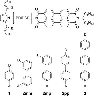 | ||
| Fig. 1 Chemical structures of the linearly conjugated DBA systems 1, 2pp, and 3, the doubly cross-conjugated 2mm, and the singly cross-conjugated 2mp biphenyl bridge. | ||
2 Results and discussion
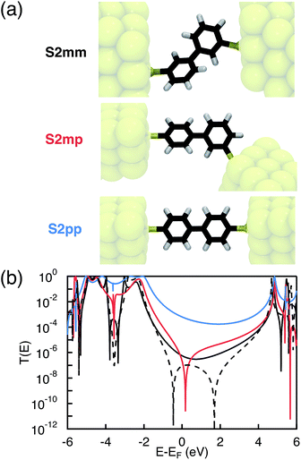
Photoinduced electron and hole transfer were studied through the DBA molecules shown in Fig. 1. These molecules are composed of a pyrrole derivative (SNS) as electron donor, a perylenediimide (PDI) electron acceptor and different n-phenylene bridges. We consider here three linearly conjugated bridges: 1, 2pp and 3 and two cross conjugated bridges: the doubly cross-conjugated 2mm and the singly cross-conjugated 2mp. To rule out a possible effect of the bridge energetics on the charge transfer rates, cross-conjugation is introduced using a chemically equivalent biphenyl bridge and substituting the donor and the acceptor to the bridge at different positions. In 2mm the donor and the acceptor are both connected to the biphenyl bridge in meta position. In 2mp, the donor is in meta position while the acceptor is in para position. Finally, both the donor and the acceptor are para substituted in 2pp. Because of their equal energetics, we particularly focus on the three biphenyl bridges 2mm, 2mp and 2pp. The study of 1 and 3 allows to put our results for the biphenyl bridges in perspective.As mentioned in the introduction, we particularly focus on the comparison of photoinduced charge transfer across the three biphenyl bridges of the DBA systems 2mm, 2mp, and 2pp with conductance properties of the same bridges embedded in a MBM junction. Therefore, before presenting the results on photoinduced charge transfer, we will briefly discuss the trend in molecular conductance of these bridges in a MBM junction. To this end, the donor and acceptor moieties were replaced by thiol groups to anchor the molecular bridges to gold electrodes, resulting in the three MBM junctions S2mm, S2mp, and S2pp as shown in Fig. 2(a).
The conductance of a molecular bridge in a MBM junction is (in the low bias limit) proportional to the square of the electronic transmission coefficient T(E) of the junction at the Fermi energy EF of the electrode:  . This transmission coefficient represents the probability that an electron with an energy E will cross the junction. Using the non-equilibrium Green function approach, T(E) can be written as:
 | (1) |
2.1 Experimental electron and hole transfer rates
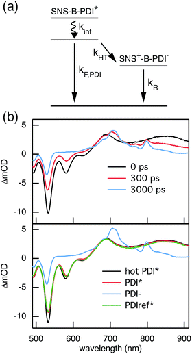
The rates of electron and hole transfer along the DBA molecules shown in Fig. 1 were experimentally determined using femtosecond transient absorption spectroscopy using a tunable Yb:KGW laser system with a time resolution of ca. 200 fs in a spectral window of 490–910 nm (details in ESI†). We call electron transfer the process where the electron donor (SNS) is excited and the excited electron transfers to the electron acceptor (PDI). Hole transfer is the process where the electron acceptor is excited and the generated hole transfers to the electron donor. In Fig. 3 the ground-state absorbance spectra of the studied molecules and the separate PDI and SNS fragments are shown. The maximum absorbance of PDI located at 527 nm shows no overlap with the absorbance of SNS. This allows selective excitation of the electron acceptor and thus the exclusive study of hole transfer. Upon excitation, the excited PDI can subsequently decay via hole transfer forming PDI−˙. This can be seen in Fig. 4(b) where the temporal evolution of the difference absorbance (ΔOD) spectra of 2pp is shown. Immediately upon excitation, the ΔOD spectrum matches the one of PDI*, which is obtained from an independent measurement of neat PDI (PDIref*). Within a few nanoseconds, this spectrum transforms into a neat spectrum of PDI−˙ (blue spectrum in Fig. 4(b)). Because of the overlap of the two spectra, the rate constant of the formation of PDI−˙ could not be deduced from kinetic traces at a single wavelength. Therefore, global and target analysis was performed using the open source software Glotaran52 (details in ESI†). The two-dimensional datasets obtained upon excitation at 527 nm were modelled with the sequential kinetic scheme describing the underlying photophysical processes depicted in Fig. 4(a). The initially excited PDI (hot PDI*) undergoes internal relaxation within the first picoseconds53 with rate constant kint. Subsequently, hole transfer occurs. For all samples, the rate constant of hole transfer kHT is at least one order of magnitude higher than the competing radiative decay of PDI*. The rate constant of the radiative decay kF,PDI was fixed to 2.5 × 10⁻⁴ ps−1 in the fits for all samples. This value was obtained from an independent measurement of neat PDI and is in agreement with previous observations.53 Although the photoinduced spectrum of SNS+˙ is outside the spectral range of our experimental setup and could thus not be observed, the rate constant of PDI−˙ formation could be set equal to kHT because previous work by Weiss et al.54 has shown that no hole transfer occurs to the phenylene bridge. All rate constants obtained from target analysis are listed in Table 1. The ΔOD spectra of hot PDI*, PDI*, and PDI−˙, which are also obtained from target analysis, are shown in the bottom graph of Fig. 4(b).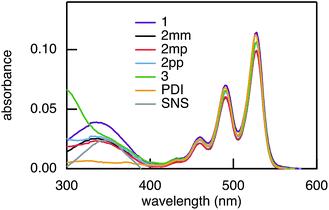 | ||
| Fig. 3 Ground-state absorbance spectra of 1, 2mm, 2mp, 2pp, and 3, and of the donor and acceptor reference compounds SNS and PDI. | ||
| Ex. at 527 nm | Ex. at 350 nm | |||||
|---|---|---|---|---|---|---|
| k int | k HT | k R | k HT | k ET | k R | |
| 1 | 0.37 | 0.043 | 1.1 × 10⁻³ | 0.028 | 0.35 | 8.6 × 10⁻⁴ |
| 2mm | 0.18 | 0.014 | 6.4 × 10⁻⁴ | 0.013 | 0.13 | 6.2 × 10⁻⁴ |
| 2mp | 0.31 | 0.0040 | 1.0 × 10⁻⁴ | 0.0038 | 0.18 | 5.4 × 10⁻⁵ |
| 2pp | 0.25 | 0.0025 | 7.1 × 10⁻⁵ | 0.0024 | 0.25 | 4.3 × 10⁻⁵ |
| 3 | 0.23 | 0.0012 | 4.6 × 10⁻⁵ | 0.0010 | 0.17 | 1.9 × 10⁻⁵ |
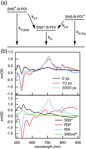
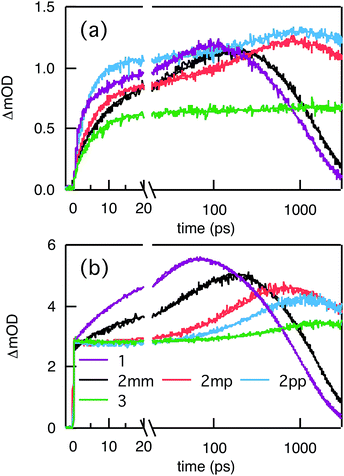
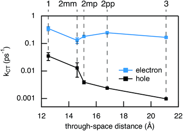
Compared to kHT, determining the rate constant of electron transfer was less straight forward as the maximum absorbance of SNS around 350 nm overlaps with a relatively small absorbance by PDI. Therefore, excitation at 350 nm not only triggers electron transfer from the excited SNS but also hole transfer from the PDI excited state. Modeling the datasets for all samples upon excitation at 350 nm involved therefore a kinetic scheme, in which electron and hole transfer occur parallel to each other, as depicted in Fig. 5(a). The internal relaxation of PDI* is omitted in the fitting procedure for simplicity. The simultaneous excitation at 350 nm can be seen in the ΔOD spectrum at 0 ps in Fig. 5(b), which shows features of the PDI* spectrum on top of a positive band between 500 and 600 nm. The latter band is ascribed to SNS*. After a few nanoseconds a neat PDI−˙ spectrum is observed. Applying target analysis with the kinetic scheme of Fig. 5(a) with fixed rate constants of the radiative decays of PDI* (2.5 × 10⁻⁴ ps−1) and SNS* (2.7 × 10⁻³ ps−1) yields all remaining rate constants (Table 1) as well as the ΔOD spectra of SNS*, PDI*, and PDI−˙ (bottom graph of Fig. 5(b)). While the spectrum of PDI−˙ is identical to the one obtained at 527 nm excitation, spectra of PDI* and SNS* deviate from the excited state spectra of neat PDI and SNS. This is due to the difficulty of disentangeling the two simultaneously excited species. Nevertheless, the coincident values of kHT obtained from target analysis of data from 527 nm and 350 nm-excitation demonstrate the validity of the applied analysis. The quality of the fits is shown in Fig. 6 where the experimental and fitted kinetic traces at 710 nm for both excitations are displayed for all samples. As seen in this figure, excellent fits were obtained for each DBA molecule. These kinetic traces qualitatively reflect the rates of electron and hole transfer in the studied DBA systems. The corresponding rate constants of electron transfer kET and hole transfer kHT are listed in Table 1 and plotted against the donor–acceptor distance in Fig. 7.
As seen in Fig. 7, the electron transfer rate constants are 1–2 orders of magnitude larger than the hole transfer rates. Additionally, the distance dependence for electron transfer is much weaker than for hole transfer. For electron transfer, the effect of conjugation on the transfer rate seems to comply with the prediction based on T(E) calculations for the equivalent MBM junctions: i.e. the electron transfer rate of 2pp is larger than of 2mm and 2mp. One could conclude that destructive quantum interference hampers the charge transfer along 2mm and 2mp. However, the differences in kET along these three bridges are much smaller than expected in the case of quantum interference effects.
Remarkably, the relation between conjugation and rate constant is reversed when considering hole transfer: kHT of 2mm is larger than of 2mp and 2pp. This trend is exactly opposite to the trend observed for the electronic conduction of these bridges as represented in Fig. 2(b). This unexpected result clearly demonstrates that a given molecular bridge can behave very differently in a MBM junction and in a DBA system.
2.2 Electron and hole transfer parameters
To understand why electron and hole transfer along the different molecules studied here are so different from each other and from the molecular conductance, we compare the experimental values of the rate constants to charge transfer parameters obtained from DFT calculations using the Amsterdam Density Functional software.50 The alkyl chains attached to the PDI unit were replaced by hydrogen atoms in all calculations. The ground state geometries of the different DBA molecules were hence optimized using a DZP basis set and the M06-2X functional.51 To do so, the ground state geometries of the isolated donor-bridge, bridge-acceptor, and the isolated bridge fragments were first fully relaxed. These fragments were then assembled to form the DBA molecules whose geometry were optimized with respect of the rotation angles between the different fragments while keeping the rest of the structure fixed. The resulting structures were used to evaluate the charge transfer rates. In the context of non-adiabatic charge transfer theory, the rate constant kCT for the transition between one initial and one final state is proportional to the square of the effective electronic coupling Jeff: | (2) |
The Franck–Condon factor FC is, in semi-classical Marcus theory,55 expressed as
 | (3) |
 | (4) |
 . The weights
 ![[capital script C]](https://www.rsc.org/images/entities/char_e522.gif) x of the fragment orbitals X in this linear combination were directly obtained from the TD-DFT calculations with the fragment orbitals used as basis set and are listed in Table 2.
x of the fragment orbitals X in this linear combination were directly obtained from the TD-DFT calculations with the fragment orbitals used as basis set and are listed in Table 2.
![[capital script C]](https://www.rsc.org/images/entities/char_e522.gif) X of the fragment orbitals X in the initial state description for electron transfer
X of the fragment orbitals X in the initial state description for electron transfer
| LUMOSNS | LUMOPhn | LUMO + 1Phn | LUMO + 5Phn | |
|---|---|---|---|---|
| 1 | 0.57 | 0.43 | ||
| 2mm | 0.70 | 0.18 | 0.12 | |
| 2mp | 0.66 | 0.15 | 0.19 | |
| 2pp | 0.52 | 0.48 | ||
| 3 | 0.57 | 0.33 | 0.10 |
 . It depends therefore on the magnitude of the respective Jkeff (and the respective unknown FC factor) which final state will dominate. Since the initial state is a linear combination of SNS and bridge states, its coupling to an acceptor state is composed of two terms: (i) the bridge-mediated coupling
  between the donor and acceptor and (ii) the direct coupling VBβFk between the bridge and the acceptor states:
 | (5) |
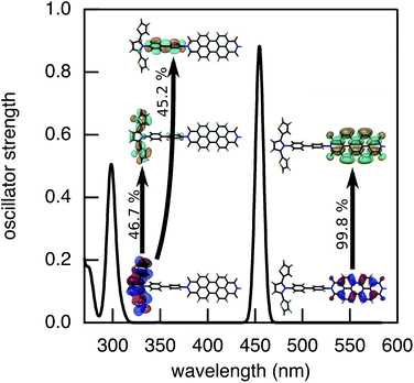
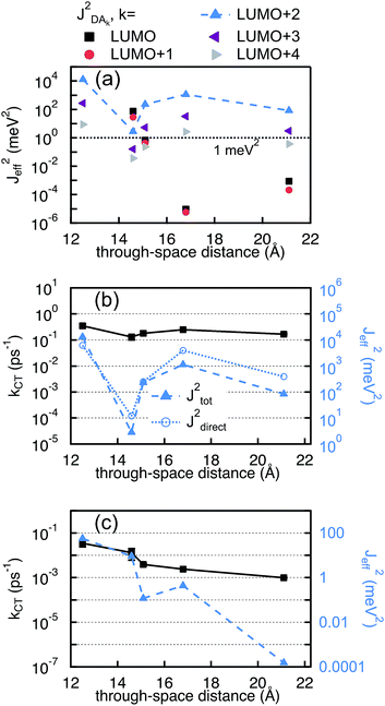
The values of JET,keff obtained for the different final states are reported in Fig. 9(a). Only 2mm and 2mp show a considerable effective coupling (≥1 meV2) between the initial delocalized state and the lowest final state on the PDI (LUMOPDI). This means that electron transfer to the LUMOPDI is essentially inhibited in the linearly conjugated molecules. The lowest final state that exhibits substantial coupling to the initial state is the LUMO + 2PDI. Our calculations therefore suggest that the electron first transfers to the LUMO + 2PDI and subsequently undergoes internal conversion to the LUMOPDI.
In contrast to electron transfer, the effective electronic coupling for hole transfer is solely composed of the bridge-mediated contribution because of the localized initial state. For such a tunneling process, comparable trends for charge transfer in DBA and MBM systems are commonly expected.43 In the present study, these expectations imply lower hole transfer rates for 2mm and 2mp as compared to 2pp. However, the comparison between the experimental kHT and (JHTeff)2 in Fig. 9(c) confirms the unexpected reduction in kHT when increasing conjugation from the doubly cross-conjugated 2mm to the linearly conjugated 2pp. This figure shows that only 1 and 2mm exhibit considerable couplings above 1 meV2. (JHTeff)2 for 2mp and 2pp is about two orders of magnitude smaller than for 2mm and (JHTeff)2 drops another four orders of magnitude for 3. It should be noted, that these values are too small to be accurately determined by DFT so that differences between 2mp, 2pp, and 3 should not be considered. The clearly different trend in the hole transfer rates in the DBA systems 2mm, 2mp, and 2pp and the conductance of the equivalent MBM junctions S2mm, S2mp, and S2pp discloses a fundamental differences between the properties of a given bridge embedded in a MBM junction and in a DBA molecule.
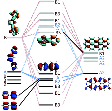
In the case of 2mp, the PDI and the phenylene bridge still share the same common C2 axis (illustrated and discussed in S.7. of ESI†). As a consequence, the fragment orbitals HOMO − 1, HOMO − 2, LUMO + 1 and LUMO + 2 of the bridge remain the only mediating pathways for hole transfer to the HOMOSNS. However, the meta-substitution of the SNS fragment lifts the degeneracy of HOMO − 1 and HOMO − 2, and LUMO + 1 and LUMO + 2 to some extend, so that the contributions of each pair cancel each other only partially. This partial cancellation results in a nonzero theoretical (JHTeff)2 and might explain the slightly larger rate constant kHT observed in 2mp than in 2pp. Note, that this difference in the computed (JHTeff)2 for 2mp and 2pp can not be seen in the results obtained with DFT (see Fig. 9(c)) because of the already mentioned inaccuracy of DFT calculations and the deviation from the prefect symmetry. Finally, in 2mm, the three fragments do not share a common axis (illustrated and discussed in S.7. of ESI†) and therefore the symmetry restrictions do not apply. This explains the relatively large effective coupling for hole transfer obtained for 2mm in comparison to 2mp and 2pp.
In the case of electron transfer, the symmetry considerations discussed above clarify why the lowest final state (LUMOPDI) is not coupled to the initial state for 1, 2pp, and 3. Both LUMOs of the SNS and of the bridge, i.e. the fragment orbitals that form the initial state of electron transfer, are antisymmetric around the C2 axis of the DBA systems. Since the LUMO of the PDI is symmetric, it can not couple to the initial state. It is hence necessary to account for higher fragment orbitals to obtain a nonzero effective coupling. As discussed above, the LUMO + 2 of PDI is the lowest antisymmetric unoccupied orbital of the electron acceptor that is coupled to the initial state for all studied DBA molecules. It therefore constitutes the primary acceptor state for electron transfer.
3 Conclusions
We have studied the effect of quantum interference on photoinduced electron and hole transfer in donor-bridge-acceptor systems containing chemically equivalent biphenyl bridges in comparison to conductance properties of the same bridges in metal-bridge-metal junctions. The computed transmission coefficients of the selected molecular bridges show pronounced quantum interference effects when embedded in a MBM junction. In particular, the transmission of the cross-conjugated bridges is significantly lower than of the linearly conjugated bridge. When connecting these bridges to donor and acceptor molecules, the experimentally determined hole transfer rate constants exhibit a reverse trend. We were able to reproduce this trends by calculations of the effective electronic coupling using density functional theory. These calculations reveal the importance of molecular orbital symmetries when studying photoinduced charge transfer in DBA systems. In the case of the linearly conjugated bridge, the majority of the pathways for hole transfer are symmetry-forbidden. Moreover, the contributions to the effective coupling of the remaining active pathways cancel each other. Consequently, the surprisingly low charge transfer rate obtained for the linearly conjugated bridge is due to destructive quantum interference. This destructive quantum interference however differs inherently from the HOMO–LUMO interference that is commonly observed in cross-conjugated MBM junctions. The destructive quantum interference obtained in the linearly conjugated DBA system originates from canceling degenerate pathways. Note that this type of destructive quantum interference is also present in the equivalent linearly conjugated MBM junction. However, other pathways provided by the bridge (e.g. HOMO and LUMO) are not switched off by symmetry and surpass this destructive interference.The comparison of charge transfer through molecular bridges in DBA systems and charge transport in MBM junctions demonstrates that, although both mechanisms can be accurately described by a coherent tunneling mechanism, the symmetry of the molecular orbitals of donor and acceptor leads to a pathway selection of certain bridge orbitals that mediate charge transfer. In DBA systems, quantum interference is thus not determined directly by the conjugation of the bridge alone, but by specific symmetry relations of the involved donor, bridge, and acceptor states. This result demonstrates that one has to be careful when explaining photoinduced charge transfer phenomena using transmission coefficients of MBM junctions in which the specific donor and acceptor moieties are neglected. Moreover, the results presented in this article point to new design principles for DBA molecules based on the symmetry of their molecular orbitals and not only on the energetic characteristics.
Acknowledgements
This work is supported by the Netherlands Organization for Scientific Research (NWO) through a VIDI grant. The research leading to these results has received funding from the European Research Council under the European Union's Seventh Framework Programme (FP/2007-2013)/ERC Grant Agreement no. 240299.References
- S. Günes, H. Neugebauer and N. S. Sariciftci, Chem. Rev., 2007, 107, 1324–1338 CrossRef PubMed.
- C. Bauer, J. Teuscher, J. C. Brauer, A. Punzi, A. Marchioro, E. Ghadiri, J. D. Jonghe, M. Wielopolski, N. Banerji and J. E. Moser, Chimia, 2011, 65, 704–709 CrossRef CAS.
- J. D. Megiatto Jr, D. D. Méndez-Hernández, M. E. Tejeda-Ferrari, A.-L. Teillout, M. J. Llansola-Portolés, G. Kodis, O. G. Poluektov, T. Rajh, V. Mujica, T. L. Groy, D. Gust, T. A. Moore and A. L. Moore, Nat. Chem., 2014, 6, 423–428 CrossRef PubMed.
- A. Aviram and M. A. Ratner, Chem. Phys. Lett., 1974, 29, 277–283 CrossRef CAS.
- M. Bockrath, D. H. Cobden, P. L. McEuen, N. G. Chopra, A. Zettl, A. Thess and R. E. Smalley, Science, 1997, 275, 1922–1925 CrossRef CAS.
- S. J. Tans, A. R. M. Verschueren and C. Dekker, Nature, 1998, 393, 49–52 CrossRef CAS.
- C. Joachim, J. K. Gimzewski and A. Aviram, Nature, 2000, 408, 541–548 CrossRef CAS PubMed.
- M. Ratner, Nat. Nanotechnol., 2013, 8, 378–381 CrossRef CAS PubMed.
- H. Song, Y. Kim, Y. H. Jang, H. Jeong, M. A. Reed and T. Lee, Nature, 2009, 462, 1039–1043 CrossRef CAS PubMed.
- N. J. Tao, Nat. Nanotechnol., 2006, 1, 173–181 CrossRef CAS PubMed.
- B. Albinsson and J. Martensson, J. Photochem. Photobiol., C, 2008, 9, 138–155 CrossRef CAS PubMed.
- G. L. Closs and J. R. Miller, Science, 1988, 240, 440–447 CAS.
- O. S. Wenger, Acc. Chem. Res., 2011, 44, 25–35 CrossRef CAS PubMed.
- J. Sukegawa, C. Schubert, X. Zhu, H. Tsuji, D. M. Guldi and E. Nakamura, Nat. Chem., 2014, 6, 899–905 CrossRef CAS PubMed.
- S. V. Aradhya and L. Venkataraman, Nat. Nanotechnol., 2013, 8, 399–410 CrossRef CAS PubMed.
- M. N. Paddon-Row, Acc. Chem. Res., 1994, 27, 18–25 CrossRef CAS.
- L. Lafferentz, F. Ample, H. Yu, S. Hecht, C. Joachim and L. Grill, Science, 2009, 323, 1193–1197 CrossRef CAS PubMed.
- W. B. Davis, W. A. Svec, M. A. Ratner and M. R. Wasielewski, Nature, 1998, 396, 60–63 CrossRef CAS.
- R. A. Malak, Z. N. Gao, J. F. Wishart and S. S. Isied, J. Am. Chem. Soc., 2004, 126, 13888–13889 CrossRef CAS PubMed.
- S. H. Choi, B. Kim and C. D. Frisbie, Science, 2008, 320, 1482–1486 CrossRef CAS PubMed.
- T. Hines, I. Diez-Perez, J. Hihath, H. Liu, Z.-S. Wang, J. Zhao, G. Zhou, K. Mllen and N. Tao, J. Am. Chem. Soc., 2010, 132, 11658–11664 CrossRef CAS PubMed.
- X. Zhao, C. Huang, M. Gulcur, A. S. Batsanov, M. Baghernejad, W. Hong, M. R. Bryce and T. Wandlowski, Chem. Mater., 2013, 25, 4340–4347 CrossRef CAS.
- M. Bixon and J. Jortner, J. Am. Chem. Soc., 2001, 123, 12556–12567 CrossRef CAS PubMed.
- Y. A. Berlin, A. L. Burin and M. A. Ratner, Chem. Phys., 2002, 275, 61–74 CrossRef CAS.
- F. D. Lewis, H. Zhu, P. Daublain, T. Fiebig, M. Raytchev, Q. Wang and V. Shafirovich, J. Am. Chem. Soc., 2006, 128, 791–800 CrossRef CAS PubMed.
- F. C. Grozema, Y. A. Berlin, L. D. Siebbeles and M. A. Ratner, J. Phys. Chem. B, 2010, 114, 14564–14571 CrossRef CAS PubMed.
- P. Sautet and C. Joachim, Chem. Phys. Lett., 1988, 153, 511–516 CrossRef CAS.
- G. C. Solomon, D. Q. Andrews, T. Hansen, R. H. Goldsmith, M. R. Wasielewski, R. P. V. Duyne and M. A. Ratner, J. Chem. Phys., 2008, 129, 054701 CrossRef PubMed.
- G. C. Solomon, D. Q. Andrews, R. H. Goldsmith, T. Hansen, M. R. Wasielewski, R. P. V. Duyne and M. A. Ratner, J. Am. Chem. Soc., 2008, 130, 17301–17308 CrossRef CAS PubMed.
- D. Q. Andrews, G. C. Solomon, R. P. V. Duyne and M. A. Ratner, J. Am. Chem. Soc., 2008, 130, 17309–17319 CrossRef CAS PubMed.
- T. Hansen, G. C. Solomon, D. Q. Andrews and M. A. Ratner, J. Chem. Phys., 2009, 131, 194704 CrossRef PubMed.
- S. Chen, Y. Zhang, S. Koo, H. Tian, C. Yam, G. Chen and M. A. Ratner, J. Phys. Chem. Lett., 2014, 5, 2748–2752 CrossRef CAS.
- N. Renaud, M. A. Ratner and C. Joachim, J. Phys. Chem. B, 2011, 115, 5582–5592 CrossRef CAS PubMed.
- T. Markussen, R. Stadler and K. S. Thygesen, Nano Lett., 2010, 10, 4260–4265 CrossRef CAS PubMed.
- A. A. Kocherzhenko, F. C. Grozema and L. D. A. Siebbeles, J. Phys. Chem. C, 2010, 114, 7973–7979 CAS.
- M. Mayor, H. B. Weber, J. Reichert, M. Elbing, C. V. Hanisch, D. Beckmann and M. Fischer, Angew. Chem., Int. Ed. Engl., 2003, 42, 5834–5838 CrossRef CAS PubMed.
- C. R. Arroyo, S. Tarkuc, R. Frisenda, J. S. Seldenthuis, C. H. Woerde, R. Eelkema, F. C. Grozema and H. S. Van der Zant, Angew. Chem., Int. Ed. Engl., 2013, 52, 3152–3155 CrossRef CAS PubMed.
- C. M. Guedon, H. Valkenier, T. Markussen, K. S. Thygesen, J. C. Hummelen and S. J. Van der Molen, Nat. Nanotechnol., 2012, 7, 304–308 CrossRef PubMed.
- S. V. Aradhya, J. S. Meisner, M. Krikorian, S. Ahn, R. Parameswaran, M. L. Steigerwald, C. Nuckolls and L. Venkataraman, Nano Lett., 2012, 12, 1643–1647 CrossRef CAS PubMed.
- R. Härtle, M. Butzin, O. Rubio-Pons and M. Thoss, Phys. Rev. Lett., 2011, 107, 046802 CrossRef.
- S. Ballmann, R. Hartle, P. B. Coto, M. Elbing, M. Mayor, M. R. Bryce, M. Thoss and H. B. Weber, Phys. Rev. Lett., 2012, 109, 056801 CrossRef.
- C. Patoux, C. Coudret, J. P. Launay, C. Joachim and A. Gourdon, Inorg. Chem., 1997, 36, 5037–5049 CrossRef CAS.
- A. B. Ricks, G. C. Solomon, M. T. Colvin, A. M. Scott, K. Chen, M. A. Ratner and M. R. Wasielewski, J. Am. Chem. Soc., 2010, 132, 15427–15434 CrossRef CAS PubMed.
- M. L. Kirk, D. A. Shultz, D. E. Stasiw, D. Habel-Rodriguez, B. Stein and P. D. Boyle, J. Am. Chem. Soc., 2013, 135, 14713–14725 CrossRef CAS PubMed.
- D. M. Adams, L. Brus, C. E. D. Chidsey, S. Creager, C. Creutz, C. R. Kagan, P. V. Kamat, M. Lieberman, S. Lindsay, R. A. Marcus, R. M. Metzger, M. E. Michel-Beyerle, J. R. Miller, M. D. Newton, D. R. Rolison, O. Sankey, K. S. Schanze, J. Yardley and X. Y. Zhu, J. Phys. Chem. B, 2003, 107, 6668–6697 CrossRef CAS.
- D. Segal, A. Nitzan, W. B. Davis, M. R. Wasielewski and M. A. Ratner, J. Phys. Chem. B, 2000, 104, 3817–3829 CrossRef CAS.
- A. Nitzan and M. A. Ratner, Science, 2003, 300, 1384–1389 CrossRef CAS PubMed.
- Y. A. Berlin and M. A. Ratner, Radiat. Phys. Chem., 2005, 74, 124–131 CrossRef CAS PubMed.
- A. Nitzan, J. Phys. Chem. A, 2001, 105, 2677–2679 CrossRef CAS.
- G. Te Velde, F. M. Bickelhaupt, E. J. Baerends, C. F. Guerra, S. J. A. V. Gisbergen, J. G. Snijders and T. Ziegler, J. Comput. Chem., 2001, 22, 931–967 CrossRef CAS PubMed.
- Y. Zhao and D. G. Truhlar, Theor. Chem. Acc., 2008, 120, 215–241 CrossRef CAS.
- J. J. Snellenburg, S. P. Laptenok, R. Seger, K. M. Mullen and I. H. M. Van Stokkum, J. Stat. Software, 2012, 49, 1–22 Search PubMed.
- C. Hippius, I. H. M. Van Stokkum, E. Zangrando, R. M. Williams and F. Wurthner, J. Phys. Chem. C, 2007, 111, 13988–13996 CAS.
- E. A. Weiss, M. J. Ahrens, L. E. Sinks, A. V. Gusev, M. A. Ratner and M. R. Wasielewski, J. Am. Chem. Soc., 2004, 126, 5577–5584 CrossRef CAS PubMed.
- R. A. Marcus and N. Sutin, Biochim. Biophys. Acta, 1985, 811, 265–322 CrossRef CAS.
- J. W. Evenson and M. Karplus, J. Chem. Phys., 1992, 96, 5272–5278 CrossRef CAS PubMed.
- K. Senthilkumar, F. C. Grozema, F. M. Bickelhaupt and L. D. A. Siebbeles, J. Chem. Phys., 2003, 119, 9809–9817 CrossRef CAS PubMed.
- S. Skourtis and A. Nitzan, J. Chem. Phys., 2003, 119, 6271–6276 CrossRef CAS PubMed.
- T. R. Prytkova, D. N. Beratan and S. S. Skourtis, Proc. Natl. Acad. Sci. U. S. A., 2007, 104, 802–807 CrossRef CAS PubMed.
- N. Gorczak, S. Tarkuc, N. Renaud, A. J. Houtepen, R. Eelkema, L. D. Siebbeles and F. C. Grozema, J. Phys. Chem. A, 2014, 118, 3891–3898 CrossRef CAS PubMed.
Footnotes |
| † Electronic supplementary information (ESI) available: Details on the synthesis and characterization of 1, 2mm, 2mp, 2pp, and 3, details on the experimental methodology, xyz-coordinates for all structures used in the calculations, details on the presence of destructive interference in S2mm, details on the orbital symmetry considerations. See DOI: 10.1039/c5sc01104c |
| ‡ Present address: Department of Biomedical Engineering, Near East University, TRNC Mersin 10, Turkey. |
| This journal is © The Royal Society of Chemistry 2015 |

