 Open Access Article
Self-assembling 1D core/shell microrods by the introduction of additives: a one-pot and shell-tunable method†
Jun
Xu
,
Hongde
Yu
,
Liulin
Yang
,
Guanglu
Wu
,
Zhiqiang
Wang
,
Dong
Wang
and
Xi
Zhang
*
MOE Key Lab of Organic Optoelectronics & Molecular Engineering, Department of Chemistry, Tsinghua University, Beijing 100084, P. R. China. E-mail: xi@mail.tsinghua.edu.cn
First published on 3rd June 2015
Abstract
Herein, we have developed a one-pot method for the fabrication of one-dimensional core/shell microrods with tunable shell compositions by the introduction of additives. Crystalline dimethyl melamine hydrochloride was utilized as the core, while melamine derivatives with different functional groups, such as pyrene, thiophene and naphthalene diimide, served as additives to regulate the core morphology and were adsorbed as the shell. The length and width of these one-dimensional structures can be tuned by varying the molar ratio of core and shell molecules as well as their total concentration. Through X-ray diffraction, the detailed molecular arrangements within the core of the microrods were revealed, and the selective effect of additives on specific crystal faces was evaluated. It is anticipated that this work may provide a facile approach for the fabrication of one-dimensional functional materials.
Introduction
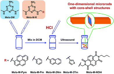
One-dimensional (1D) micro/nanostructures are suitable for the transport of electrons, photons and excitons because of the size confinement effect.1–8 Therefore, they have attracted significant attention due to their abundant applications in the fabrication of electronic, photonic and optoelectronic micro/nano devices.9–14 Recently, increasing efforts have been made to fabricate 1D micro/nanostructures with multiple components and novel topologies (segmented, core/shell or branched) to achieve more complex functionalities.15–23 1D micro/nanomaterials with core/shell structures have shown potential applications in various fields such as transistors,24,25 solar cells,26–28 gas sensing,29,30 photocatalysis,31 lithium-ion batteries32 and so on.33–35 Lieber et al. have synthesized core/shell nanowires with versatile shell compositions by chemical vapor deposition on the nanowire surface, which can be applied for the preparation of coaxially gated nanowire field-effect transistors.24 Yao and Zhao et al. have prepared core/sheath nanowire optical waveguides by a co-precipitation method, which can be used for rapid and sensitive optical detection of gaseous hydrogen peroxide.29 However, despite these successful examples, it is still a significant challenge to fabricate 1D core/shell structures with tunable shell compositions by a convenient approach.Herein, we have developed a convenient additive-adsorption method for the fabrication of 1D core/shell microrods with tunable shell compositions. Crystalline dimethyl melamine hydrochloride (Mela-DM·HCl) formed the core, while various melaminium derivatives (Mela-M-R, R = Pym, Pm, 2Nm, 3Tm, NDI4, shown in Scheme 1) were utilized as additives to regulate the core morphology and adsorbed as the shell. Simply mixing Mela-DM with Mela-M-R in dichloromethane (DCM) and adding an equimolar amount of hydrochloric acid (HCl) led to the formation of self-assembled 1D core/shell microrods with the required shell compositions. X-ray diffraction (XRD) was performed to elucidate the possible effect of additives on inducing the 1D morphology.
Results and discussion
Self-assembled structures of Mela-DM·HCl
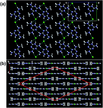
The self-assembly of Mela-DM with HCl in DCM leads to the formation of micrometer-sized quadrangular prisms (Fig. S1†). These microstructures have rhombus-shaped bases with vertex angles of 50°. Single crystal XRD was employed to reveal the molecular arrangements of Mela-DM·HCl. As shown in Fig. 1, protonated Mela-DM molecules are connected by chloride ions to form ribbons, and each ribbon stacks with four adjacent ribbons in the perpendicular direction to produce a 3D network. The driving forces are combined intermolecular interactions, including chloride ion mediated hydrogen bonding and electrostatic interaction in one direction, and π–π stacking and hydrogen bonding in the other two directions. Based on the above results, the exposed crystal faces in the Mela-DM·HCl microstructures can be determined to be (0,1,0), (1,0,1) and (1,0,−1), and the rhombus-shaped bases correspond to the (0,1,0) face (Fig. S1b†). It should be noted that the (1,0,1) and (1,0,−1) faces are identical. Therefore, if the growth perpendicular to the (1,0,1) face can be suppressed by the introduction of additives, 1D structures could be obtained; otherwise, two-dimensional (2D) assemblies would result.Fabrication of 1D core/shell microrods
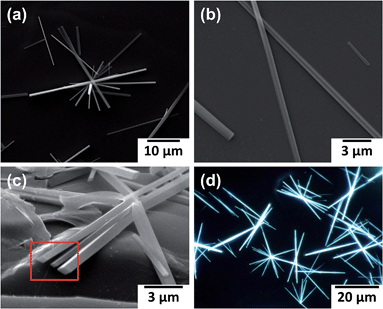
In a typical preparation procedure, 4.5 mL of Mela-DM solution (1.0 mM in DCM) was mixed with 0.5 mL of Mela-M-R (R = Pym, Pm, 2Nm, 3Tm, NDI4) solution (1.0 mM in DCM) to obtain a two-component solution with 10% Mela-M-R, and then 1.4 μL of HCl (3.5 M in H2O) was added. After sonication for 1 min and standing for several hours at room temperature, the solution became turbid, indicating the formation of assemblies of large size. Generally, the suspension should be allowed to stand for at least three days to ensure that equilibrium is reached. Assemblies with different molar ratios of Mela-M-R (5, 20%) and different concentrations (0.5, 2.0 mM) were prepared by similar procedures.The self-assembly of Mela-DM/Mela-M-Pym (10%)·HCl (1 mM) results in the formation of 1D microrods. As indicated by the scanning electron microscopy (SEM) images in Fig. 2a and b, the length of the 1D assemblies is in the tens of micrometers, while the width is several hundred nanometers, which is quite uniform. Moreover, side-view SEM reveals that the microrods have rhombus-shaped cross sections with vertex angles of about 50° (Fig. 2c), which probably correspond to the (0,1,0) crystal face. Therefore, the growth perpendicular to the (0,1,0) face may have been relatively enhanced because of the introduction of additives. Furthermore, the fluorescence microscopy image in Fig. 2d shows that the microrods emit strong blue fluorescence when excited by UV light (330–385 nm), while the confocal fluorescence microscopy image in Fig. S2† shows that the periphery of the microrod exhibits much stronger fluorescence than its middle, indicating the formation of core/shell microrods with fluorescent Mela-M-Pym as the shell. The fluorescence spectrum of the microrods was recorded and is shown in Fig. S3;† the peaks at 380, 399 and 422 nm represent the emission of the monomer, while the broad peak around 450 nm corresponds to the aggregated state of pyrene.
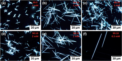
The length and width of the 1D microrods can be tuned by varying the molar ratio of Mela-DM/Mela-M-Pym and the total concentration. As shown in Fig. 3a–c, increasing the molar ratio of Mela-M-Pym from 5% to 10% causes the width of the 1D microrods to narrow and the length to increase, but further increasing the molar ratio to 20% does not cause much change in the morphology of the 1D structures. In Fig. 3c, we can also observe the appearance of fluorescent dots formed by Mela-M-Pym·HCl (SEM and fluorescence microscopy images shown in Fig. S4†), which means that further increasing the molar ratio of Mela-M-Pym leads to the assembly of Mela-M-Pym with HCl instead of co-assembly with Mela-DM·HCl, thus having little effect on the morphology change of the 1D microrods. Moreover, lowering the total concentration of the melamine moiety from 2.0 mM to 0.5 mM causes the 1D microrods to lengthen from about 10 micrometers to over 50 micrometers (Fig. 3d–f).
Growth mechanism of 1D core/shell microrods
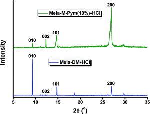
In order to investigate the growth mechanism of the 1D core/shell microrods, powder XRD was performed for the unground samples of Mela-DM·HCl microstructures and Mela-DM/Mela-M-Pym (10%)·HCl microrods to reveal the molecular arrangements. As shown in Fig. 4, the diffraction peaks in the XRD pattern of Mela-DM/Mela-M-Pym (10%)·HCl microrods were almost the same as for Mela-DM·HCl, except for the difference in their intensity. This means that Mela-DM·HCl in the microrods is in a crystalline state, with the same molecular arrangements as displayed in Fig. 1. Nevertheless, compared with Mela-DM·HCl microstructures, the peak intensity of the (0,1,0) face for Mela-DM/Mela-M-Pym (10%)·HCl microrods decreased dramatically, while the intensity of the (0,0,2), (1,0,1) and (2,0,0) faces was relatively increased. This result indicates that, for crystalline Mela-DM·HCl within the microrods, the growth perpendicular to the (0,1,0) face is relatively strengthened, which is consistent with the SEM observation (Fig. 2c). This may be caused by the introduction of Mela-M-Pym additives, which have a similar structure to Mela-DM and may interact with specific faces of crystalline Mela-DM·HCl, thus changing the growth rates of the (0,1,0) and (1,0,1) faces, resulting in the elongation of the Mela-DM·HCl microstructures to form 1D microrods. The additives adsorb on the microrods to form core/shell structures, in which the crystalline Mela-DM·HCl forms the core portion, and the adsorbed Mela-M-Pym constitutes the shell. It should be noted that the microrods are shortened in length and broadened in width when prepared at −20 °C (Fig. S5†), which supports the hypothesis that the 1D structures are the kinetically controlled products.As the additives may alter the growth kinetics of different crystal faces and induce the formation of 1D microrods, in order to clarify the selective effect of additives on the (0,1,0) and (1,0,1) faces, it is necessary to investigate the growth mechanisms of the aforementioned faces. Based on different interface structures, the crystal growth mechanisms have been classified mainly into two modes: the continuous growth mechanism and 2D nucleation growth mechanism.36,37 The Mela-DM·HCl crystal exhibits a chloride ion mediated, hydrogen bonded ribbon in the direction perpendicular to the (0,1,0) face, while the (1,0,1) face is almost parallel to the ribbon. Therefore, many hydrogen bonding sites are exposed on the (0,1,0) face (Fig. S6a†), which are suitable for the direct inclusion of Mela-DM into the crystal lattice; thus, the growth mechanism may be continuous growth. Whereas, since only methyl groups are exposed on the (1,0,1) face (Fig. S6b†), it may grow through a 2D nucleation mechanism in which the formation of a stable crystalline nucleus on the surface is the rate-determining step. This is analogous to the paradigmatic case of urea.38 Since Mela-M-Pym shares remarkable structural similarity with Mela-DM, it may compete for the adsorption sites and affect the growth of the (0,1,0) face. Meanwhile, Mela-M-Pym may adsorb on the (1,0,1) face and inhibit the nucleation process due to the steric hindrance effect of pyrene, which is fatal to the growth of the (1,0,1) face. The additives may have a greater inhibition effect on the growth of the (1,0,1) face than the (0,1,0) face. As a result, the (1,0,1) face grows more slowly than the (0,1,0) face when the Mela-DM·HCl crystal is exposed to Mela-M-Pym, resulting in the formation of 1D structures.
As the appended pyrene groups may be responsible for the suppressed growth on the (1,0,1) face, it was anticipated that additives with different substituent groups could also be used for the fabrication of 1D structures. To answer this question, the R substituent of Mela-M-R was varied from pyrene to benzene, naphthalene, thiophene and naphthalene diimide. As indicated by the SEM image in Fig. S7,† self-assembly of Mela-DM/Mela-M-R (R = Pm, 2Nm, 3Tm, NDI4) led to the formation of 1D microrods in the presence of HCl. It is notable that additives with benzene, naphthalene and thiophene groups induced the formation of 1D microrods with a smaller length/width ratio compared with pyrene (Table S1†), because these small substituents may have a relatively weak steric hindrance effect. These results further demonstrate that the formation of 1D structures is due to the suppressed growth of the (1,0,1) face caused by the steric hindrance of additives. Therefore, this method can be expanded to the preparation of 1D core/shell microrods with diverse shell molecules.
Tuning the fluorescence of Mela-DM/Mela-M-Pym (10%)·HCl
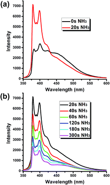
Given that HCl is incorporated into the Mela-DM/Mela-M-Pym (10%)·HCl microrods, the fluorescence of the adsorbed pyrene groups may be tuned by treatment with ammonia gas. As shown in Fig. 5a, after exposure to ammonia for a mere 20 s, the emission of the pyrene monomer increased greatly and the fluorescence of the aggregated state decreased, while the morphology of the microrods was almost unchanged (Fig. S8†). This may be explained as follows: ammonia could permeate into the shell of the microrods and interact with HCl, and the resulting products may remain in the shell portion and prevent the stacking of pyrene chromophores. As the exposure time may not be enough for ammonia to reach the core portion, the structure of the microrods was still intact.Interestingly, increasing the exposure time to ammonia leads to the attenuation of the fluorescence intensity. As shown in Fig. 5b, when the exposure time was increased from 20 s to 300 s, the fluorescence of the sample decreased significantly. Meanwhile, fluorescence microscopy and SEM images indicated that the structure of the microrods was gradually disrupted (Fig. S9†). As a stronger base than melamine, ammonia could permeate into the microrods and bind with HCl, which would break the chloride ion bridging interactions and cause the decomposition of the microrods. During this process, the pyrene moieties in the shell may be buried into the core, thus resulting in a decrease in the fluorescence.
Conclusions
In conclusion, we have successfully prepared 1D core/shell microrods with crystalline Mela-DM·HCl as the core and various Mela-M-R derivatives forming the shell in a convenient additive-adsorption approach. The length and width of the 1D structures can be tuned by varying the molar ratio of Mela-DM/Mela-M-Pym and the total concentration. Furthermore, the selective effect of additives on the growth of specific crystal faces was evaluated, providing a possible growth mechanism for the 1D structures. It is anticipated that various functional groups could be attached to the additive molecules, thus providing a facile approach to fabricate 1D core/shell structures with potential applications in areas such as organic field-effect transistors and organic photonic materials.Acknowledgements
This work was financially supported by the Foundation for Innovative Research Groups of the National Natural Science Foundation of China (21121004) and the National Basic Research Program of China (2013CB834502). The authors thank Prof. Kaibei Yu and Prof. Ruji Wang for single crystal XRD data collection and structure determination. We also thank Mr Yu Yi for his help in drawing the TOC picture.Notes and references
- J. P. Hill, W. Jin, A. Kosaka, T. Fukushima, H. Ichihara, T. Shimomura, K. Ito, T. Hashizume, N. Ishii and T. Aida, Science, 2004, 304, 1481 CrossRef CAS PubMed.
- L. C. Palmer and S. I. Stupp, Acc. Chem. Res., 2008, 41, 1674 CrossRef CAS PubMed.
- L. Zang, Y. Che and J. S. Moore, Acc. Chem. Res., 2008, 41, 1596 CrossRef CAS PubMed.
- Y. Zhao, H. Fu, A. Peng, Y. Ma, D. Xiao and J. Yao, Adv. Mater., 2008, 20, 2859 CrossRef CAS PubMed.
- C. Wang, Y. Guo, Y. Wang, H. Xu, R. Wang and X. Zhang, Angew. Chem., Int. Ed., 2009, 48, 8962 CrossRef CAS PubMed.
- H. Liang, S. Liu and S. Yu, Adv. Mater., 2010, 22, 3925 CrossRef CAS PubMed.
- L. Tian, R. Szilluweit, R. Marty, L. Bertschi, M. Zerson, E. Spitzner, R. Magerle and H. Frauenrath, Chem. Sci., 2012, 3, 1512 RSC.
- N. P. Dasgupta, J. Sun, C. Liu, S. Brittman, S. C. Andrews, J. Lim, H. Gao, R. Yan and P. Yang, Adv. Mater., 2014, 26, 2137 CrossRef CAS PubMed.
- J. Kong, N. R. Franklin, C. Zhou, M. G. Chapline, S. Peng, K. J. Cho and H. Dai, Science, 2000, 287, 622 CrossRef CAS.
- Y. Huang, X. Duan, Q. Wei and C. M. Lieber, Science, 2001, 291, 630 CrossRef CAS PubMed.
- J. Zhao, J. I. Wong, C. Wang, J. Gao, V. Z. Ng, H. Y. Yang, S. C. Loo and Q. Zhang, Chem.–Asian J., 2013, 8, 665 CrossRef CAS PubMed.
- Q. Cui, Y. Zhao and J. Yao, Chem. Sci., 2014, 5, 52 RSC.
- B. Weng, S. Liu, Z. Tang and Y. Xu, RSC Adv., 2014, 4, 12685 RSC.
- Y. Ma, M. Xue, J. Shi and Y. Tan, Nanoscale, 2014, 6, 6828 RSC.
- S. J. Hurst, E. K. Payne, L. Qin and C. A. Mirkin, Angew. Chem., Int. Ed., 2006, 45, 2672 CrossRef CAS PubMed.
- A. J. Mieszawska, R. Jalilian, G. U. Sumanasekera and F. P. Zamborini, Small, 2007, 3, 722 CrossRef CAS PubMed.
- X. Wang and C. S. Ozkan, Nano Lett., 2008, 8, 398 CrossRef CAS PubMed.
- Y. Ner, J. G. Grote, J. A. Stuart and G. A. Sotzing, Angew. Chem., Int. Ed., 2009, 48, 5134 CrossRef CAS PubMed.
- C. Meng, Y. Xiao, P. Wang, L. Zhang, Y. Liu and L. Tong, Adv. Mater., 2011, 23, 3770 CAS.
- Q. Cui, L. Jiang, C. Zhang, Y. Zhao, W. Hu and J. Yao, Adv. Mater., 2012, 24, 2332 CrossRef CAS PubMed.
- Q. Wen, J. Di, Y. Zhao, Y. Wang, L. Jiang and J. Yu, Chem. Sci., 2013, 4, 4378 RSC.
- Y. Zhang, L. Zhang, R. Deng, J. Tian, Y. Zong, D. Jin and X. Liu, J. Am. Chem. Soc., 2014, 136, 4893 CrossRef CAS PubMed.
- J. Zhang, C. Wang, W. Chen, J. Wu and Q. Zhang, RSC Adv., 2015, 5, 25550 RSC.
- L. J. Lauhon, M. S. Gudiksen, D. Wang and C. M. Lieber, Nature, 2002, 420, 57 CrossRef CAS PubMed.
- D. C. Dillen, K. Kim, E. S. Liu and E. Tutuc, Nat. Nanotechnol., 2014, 9, 116 CrossRef CAS PubMed.
- A. L. Briseno, T. W. Holcombe, A. I. Boukai, E. C. Garnett, S. W. Shelton, J. J. Frechet and P. Yang, Nano Lett., 2010, 10, 334 CrossRef CAS PubMed.
- J. Tang, Z. Huo, S. Brittman, H. Gao and P. Yang, Nat. Nanotechnol., 2011, 6, 568 CrossRef CAS PubMed.
- Y. Shi, L. Tan, L. Chen and Y. Chen, Macromolecules, 2014, 47, 1757 CrossRef CAS.
- J. Zheng, Y. Yan, X. Wang, W. Shi, H. Ma, Y. Zhao and J. Yao, Adv. Mater., 2012, 24, OP194 CAS.
- S. J. Park, O. S. Kwon and J. Jang, Chem. Commun., 2013, 49, 4673 RSC.
- X. Peng, A. C. Santulli, E. Sutter and S. S. Wong, Chem. Sci., 2012, 3, 1262 RSC.
- B. S. Lee, H. S. Yang, H. Jung, S. Y. Jeon, C. Jung, S. W. Kim, J. Bae, C. L. Choong, J. Im, U. I. Chung, J. J. Park and W. R. Yu, Nanoscale, 2014, 6, 5989 RSC.
- Z. Deng, S. Pal, A. Samanta, H. Yan and Y. Liu, Chem. Sci., 2013, 4, 2234 RSC.
- J. S. Bykova, M. D. Lima, C. S. Haines, D. Tolly, M. B. Salamon, R. H. Baughman and A. A. Zakhidov, Adv. Mater., 2014, 26, 7510 CrossRef CAS PubMed.
- M. Mashkour, T. Kimura, F. Kimura, M. Mashkour and M. Tajvidi, RSC Adv., 2014, 4, 52542 RSC.
- G. Dhanaraj, K. Byrappa, V. Prasad and M. Dudley, Springer handbook of crystal growth, Springer, New York, 2010 Search PubMed.
- I. Sunagawa, Crystals: growth, morphology and perfection, Cambridge University Press, Cambridge, 2005 Search PubMed.
- The exposed crystal faces of urea are (0,0,1) and (1,1,0). In the direction perpendicular to the (0,0,1) face, urea molecules are connected by strong hydrogen bonding to form infinite chains, while the (1,1,0) face is parallel to the hydrogen bonded chains. Therefore, the growth mechanism of the (0,0,1) face is continuous growth, since the exposed hydrogen bonds are oriented in the growth direction to offer binding sites for urea molecules, whereas the (1,0,1) face grows following a birth and spread mechanism, since urea molecules can not be directly incorporated into the lattice for lack of strong interactions. These results have been demonstrated by molecular dynamics simulations. See: M. Salvalaglio, T. Vetter, F. Giberti, M. Mazzotti and M. Parrinello, J. Am. Chem. Soc., 2012, 134, 17221 CrossRef CAS PubMed.
Footnote |
| † Electronic supplementary information (ESI) available: SEM images of Mela-DM·HCl; confocal fluorescence microscopy image and fluorescence spectrum of Mela-DM/Mela-M-Pym·HCl microrods; SEM and fluorescence microscopy images of Mela-M-Pym·HCl; SEM image of Mela-DM/Mela-M-Pym·HCl microrods prepared at −20 °C; SEM images of Mela-DM/Mela-M-R·HCl microrods; fluorescence microscopy and SEM images of Mela-DM/Mela-M-Pym·HCl after exposure to ammonia; experimental details and compound characterization; details of the single crystal structure of Mela-DM·HCl. CCDC 1063152. For ESI and crystallographic data in CIF or other electronic format see DOI: 10.1039/c5sc01631b |
| This journal is © The Royal Society of Chemistry 2015 |

