 Open Access Article
Creative Commons Attribution 3.0 Unported Licence
Nanocarbons for mesoscopic perovskite solar cells
Munkhbayar
Batmunkh
ab,
Cameron J.
Shearer
b,
Mark J.
Biggs
ac and
Joseph G.
Shapter
*b
aSchool of Chemical Engineering, The University of Adelaide, Adelaide, South Australia 5005, Australia. E-mail: munkhbayar.batmunkh@adelaide.edu.au
bCentre for Nanoscale Science and Technology, School of Chemical and Physical Sciences, Flinders University, Bedford Park, Adelaide, South Australia 5042, Australia. E-mail: joe.shapter@flinders.edu.au; cameron.shearer@flinders.edu.au
cSchool of Science, Loughborough University, Loughborough, Leicestershire LE11 3TU, UK. E-mail: m.biggs@lboro.ac.uk
First published on 9th February 2015
Abstract
Organic–inorganic halides based perovskite solar cells (PSCs) have attracted a great deal of attention from the photovoltaic (PV) research community due to the extremely rapid increases in efficiencies observed over the past few years. The PSC is an extension of dye-sensitised solar cells and has reached an energy conversion efficiency of 19.3% by mid-2014. However, PSCs do have some disadvantages such as use of expensive metal electrodes, the high temperature required during production and poor stability when in use. There is no doubt that research with carbon nanomaterials will play an important role in understanding and solving the issues currently observed in PSCs, as they consistently have been shown to improve performance in a wide range of energy related applications. The present review (i) provides a brief introduction to PSC development; (ii) highlights the notable achievements of PSCs; (iii) particularly focuses on the use of nanocarbon in mesoscopic PSCs and (iv) predicts and suggests a roadmap for the future application of carbon materials in this emerging technology.
1 Introduction
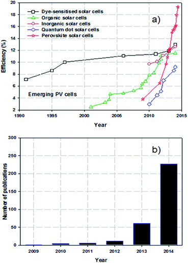
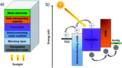
It is now widely accepted that direct conversion of the sun's energy into electricity is an unlimited clean and renewable resource that has great potential to address increasing energy demands and environmental pollution issues.1,2 The challenge for renewable solar energy conversion is to reduce production cost and maximise efficiency. At present, almost ∼90% of the commercial photovoltaic (PV) production is based on crystalline silicon (Si) solar cells which can deliver a power conversion efficiency (PCE) of approximately 20% under full-sun illumination.3 However, these Si-based PV cells suffer from high production costs and complicated manufacturing processes. As emerging PVs, several classes of technologies such as dye-sensitised solar cells (DSSCs),4 organic PVs (OPVs),5 inorganic cells (CZTSSe)6 and quantum dot solar cells (QDSCs)7 have been developed with the aim of replacing conventional Si-solar cells. Although these alternative PVs have been well explored (for at least 10 years), the improvements in PCEs have been relatively slow and have reached maximum efficiencies of only around 9.2–13% (Fig. 1a).8–12 In addition, despite vast research efforts over the last decade, the PCEs achieved for these solar cells are still far from the target efficiency of 20%. Therefore, a more innovative and efficient solar energy conversion system that can be fabricated at reasonable cost is desired.Perovskite solar cells (PSCs) evolved from DSSCs and are a new class of PV technology that have great potential to replace current commercial solar cells. A typical mesoscopic PSC is constructed using a transparent conductive oxide (TCO) film (usually fluorine doped tin oxide (FTO)), a thin, dense compact semiconducting layer that prevents short circuits, a mesoporous nanocrystalline semiconducting oxide layer, a light harvesting perovskite layer, a hole-transporting material (HTM) and a metal electrode (Au or Ag), as illustrated in Fig. 2a.13 The entire working principles of PSCs have not been satisfactorily explained and can be different depending on the exact PSC structure. It is accepted that in the case of typical PSCs: upon illumination, the perovskite layer is excited, producing an electron–hole pair. The charge carriers can then diffuse to an interface where the electrons are injected into the conduction band of the semiconducting material whilst the holes are transported to the valence band of the HTM. Finally, the electrons and holes are then collected by the conductive electrodes. The process is thermodynamically favourable when the valence and conduction band energy levels of the layers align such that the electron transport proceeds to a lower energy level whilst hole transport proceeds to higher energy levels (see Fig. 2b). During the process, the compact layer prevents shunting and leakage of the current under reverse bias. Organometal trihalide perovskite materials, CH3NH3PbX3 (X = Cl, Br, I), are implemented as the light absorber because of their broad and strong light absorption properties.
Perovskite based solar cells have attracted great attention from the PV research community due to their extraordinary light-harvesting characteristics.14 A search of the online database Scopus, plotted in Fig. 1b, shows the very rapid increase in the number of publications on PSCs. The exponential growth in publication rate is a testament to both the performance and ease of manufacture of PSCs. Over the past two years, the implementation of organic–inorganic lead halide perovskite based light absorbers into solid-state solar cells has brought breakthroughs in low-cost PVs. Interestingly, the progress of state of the art PSCs has been astounding and the highest energy conversion efficiency of 19.3% was recently reached (Fig. 1a).24 A brief overview of notable achievements of PSCs is illustrated in Fig. 3, as they are previously summarised in several recent reviews.25–37 Additionally, we describe the PSC structures that correspond to each published efficiency record from 3.8% to 19.3% (Fig. 3). The general structure of PSCs have remained similar with improvements in efficiency related to the implementation a solid-state hole transporting material and the mixing of the perovskite within the mesoporous metal oxide layer.
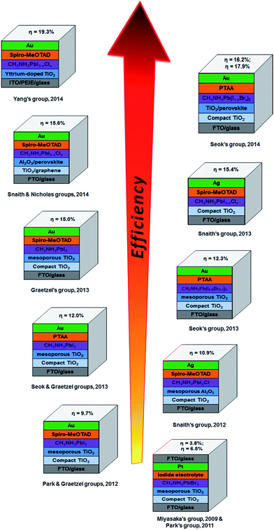 | ||
| Fig. 3 Progress in the efficiency record of PSCs since 2009 showing the structures of PSCs (constructed by the corresponding groups) used to achieve the reported energy conversion efficiencies. These PSCs have been reported in ref. 13–24. | ||
Recent breakthroughs show PV cells based on perovskite light absorbers are approaching the efficiency of commercially available Si-based solar cells.23,24 PSCs have several advantages such as remarkably high efficiency along with a simple and low cost synthesis. However, they also suffer from several drawbacks namely: (i) use of expensive, rare materials, (ii) high-temperature processing of n-type TiO2 layer, (iii) relatively slow electron transport between the perovskite and TiO2 and (iv) a lack of long-term stability. Consequently, it is necessary to overcome these issues in order to make this novel high efficiency solar cell commercially viable. Very recently, carbon nanomaterials, with their excellent conductivity and good chemical stability, have been applied in PSCs to tackle the aforementioned bottlenecks. Moreover, it should be noted that one of the efficiency records (15.6% in Fig. 3) of PSCs was achieved by the use of graphene (member of carbon family).21 This clearly indicates that carbon materials are very promising candidates for the development of this emerging technology.
Furthermore, it is no surprise that carbonaceous materials including carbon particles, carbon nanotubes (CNTs) and graphene would have significant role in the development of PSCs as they have been extensively studied in various energy related applications owing to their excellent properties, low cost and abundance.38–57 Since mid-2013, tremendous efforts have been made in the use of carbon materials in the mesoscopic PSCs. Because of this rapidly growing research interest in this advancing field, emphasising their past discoveries, achievements and developments is of great importance.
Herein, we contribute to this cutting-edge research area by providing a review that focuses on the successful application of carbon nanomaterials for perovskite-based low cost PV cells. There is little doubt that the use of carbonaceous materials will advance the PV performance of PSCs whilst maintaining low production cost.
2 Carbon based PSCs
While a great deal of important work has been done on the use of carbonaceous materials in planar heterojunction PSCs,58–63 this review will cover only the mesoscopic PSCs. The structure and operating principle of the two types of cells are very different and hence it is difficult to do justice to both architectures in one review. As shown in Fig. 2, the key components of the mesoscopic PSC are the back metal electrode, hole transporting layer (HTM), perovskite, semiconducting oxide scaffold, a blocking layer and the transparent conducting oxide. Carbon nanomaterials have been used in several of these layers and this work will be discussed in the following. The potential use of carbon nanomaterials in other sections of PSC will then be discussed.2.1 Successful applications of carbon materials in PSCs
To the best of our knowledge, Han's group64 was the first to report the implementation of carbon materials in the counter electrode of CH3NH3PbI3 based PSCs. They deposited a carbon black/graphite composite via screen printing technique on the PSC photoelectrode that consisted of FTO glass substrate, TiO2 compact layer, mesoporous TiO2 layer and ZrO2 spacer layer. Finally, the manufacturing process of the PSC was completed by drop-coating of CH3NH3PbI3 perovskite sensitiser onto the mesoscopic carbon layer (see Fig. 4a). In the carbon black/graphite composite materials, two kinds of graphite (flaky and spheroidal graphite) were used and their PV performances were compared. The highest PCE (6.64%) was achieved by PSC assembled with the spheroidal graphite based carbon composite cathodes. One of the main reasons for this good performance by carbon cathode employed PSCs is, of course, the suitable energy levels of carbon material when compared with the other components of the device. In particular, upon exposure to sunlight, the perovskite sensitiser generates electrons and holes in the conduction band (−3.93 eV) and valence band (−5.43 eV), respectively. Since the conduction band of ZrO2 is at −3.27 eV, the photo-generated electrons on CH3NH3PbI3 conduction band are directly injected into the conduction band of TiO2 (−4.0 eV) whilst the holes are transferred into the carbon (−5.0 eV) (energy levels shown in Fig. 4b).64 On the other hand, these authors have also demonstrated that the application of carbon nanomaterials in the counter electrode of PSCs not only replaced precious metal, it can also avoid using expensive organic HTMs. It should be noted that the use of the organic HTMs (e.g. namely 2,2′,7,7′-tetrakis(N,N-di-p-methoxyphenylamine)-9,9′-spirobifluorene, Spiro-OMeTAD) has some drawbacks such as high material cost and poor stability. Interestingly, the initial efficiency (6.64%) of carbon cathode employed PSC still remained at high with a PCE value (above 6.5%) even after 840 h, shown in Fig. 4c. This result suggests that the use of carbon nanomaterials in the PSC cathode can simultaneously address several limitations of this high-performance PV device.
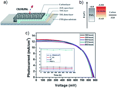 | ||
| Fig. 4 (a) The structure of the first carbon counter electrode based PSC.64 (b) Energy level of TiO2, CH3NH3PbI3 and carbon.64 (c) Current density–voltage curves of carbon cathode based PSCs over 840 hours. Inset: the effect of time on each value (Jsc, Voc, FF and PCE) of solar cell. Reprinted with permission from ref. 64 © 2013, Nature Publishing Group. | ||
A series of studies have reported applying various carbon materials as PSC cathodes with the goal of improving efficiency after the initial report from Han's group.65–73 The same group were able to further improve their previous efficiency (6.64%) to ∼10.6%![[thin space (1/6-em)]](https://www.rsc.org/images/entities/char_2009.gif) 65 by using TiO2 nanosheets on the photoelectrode and ∼11.6%
65 by using TiO2 nanosheets on the photoelectrode and ∼11.6%![[thin space (1/6-em)]](https://www.rsc.org/images/entities/char_2009.gif) 67 by optimising the thickness of the carbon counter electrodes. In their latest work,67 they explored the influence of the thickness of carbon black/graphite film (3–15 μm) on the cell performance. The best efficiency of the PSCs was achieved by employing a carbon black/graphite counter electrode with an optimised thickness of 9 μm. Meanwhile, the collaborative work of Han's and Graetzel's group reported the fabrication of hole-conductor-free and fully printable PSCs.68 Indeed, this work achieved the highest efficiency to date of carbonaceous cathode based cells. The manufacturing process of this porous carbon cathode based cell was unique in that it used 5-ammoniumvaleric acid (5-AVA) iodide based perovskite as a sensitiser. The 5-AVA played an important role in controlling the formation of perovskite crystals in the mesoporous oxide and providing better growth within the network. Consequently, the 5-AVA cations based perovskite provided good surface contact with the TiO2 and lower defect concentration. Indeed, the measured short circuit current (Jsc), open circuit voltage (Voc) and fill factor (FF) for this PSC which still used the carbonaceous cathode were 22.8 mA cm−2, of 0.86 V and 0.66, respectively and yielded a PCE of 12.8%.68
67 by optimising the thickness of the carbon counter electrodes. In their latest work,67 they explored the influence of the thickness of carbon black/graphite film (3–15 μm) on the cell performance. The best efficiency of the PSCs was achieved by employing a carbon black/graphite counter electrode with an optimised thickness of 9 μm. Meanwhile, the collaborative work of Han's and Graetzel's group reported the fabrication of hole-conductor-free and fully printable PSCs.68 Indeed, this work achieved the highest efficiency to date of carbonaceous cathode based cells. The manufacturing process of this porous carbon cathode based cell was unique in that it used 5-ammoniumvaleric acid (5-AVA) iodide based perovskite as a sensitiser. The 5-AVA played an important role in controlling the formation of perovskite crystals in the mesoporous oxide and providing better growth within the network. Consequently, the 5-AVA cations based perovskite provided good surface contact with the TiO2 and lower defect concentration. Indeed, the measured short circuit current (Jsc), open circuit voltage (Voc) and fill factor (FF) for this PSC which still used the carbonaceous cathode were 22.8 mA cm−2, of 0.86 V and 0.66, respectively and yielded a PCE of 12.8%.68
Very recently, an interesting study was reported by Wei et al.,70 who simply fabricated PSCs by clamping a mesoporous TiO2/CH3NH3PbI3 perovskite based photoelectrode to a candle-soot film. The candle soot film was prepared by holding FTO glass above the candle flame (see Fig. 5a). It can be seen from the scanning electron microscope (SEM) image in Fig. 5b that a loose sponge-like structure of candle soot was well assembled. The particle size of the candle soot was measured to be ∼30 nm based on transmission electron microscope (TEM) images of the film (Fig. 5c). In order to fabricate high-performance PSCs using this candle soot film, the authors made several systematic attempts. Their first attempt (termed 1st generation) shown in Fig. 5d featured direct assembly of the photoelectrode with a candle-soot counter electrode. The cell fabricated via the 1st generation clamping method exhibited PV efficiency of only 2.6%. This inferior performance was due to the low conductivity of the as-prepared candle-soot film and poor contact between the perovskite and candle soot. The aim of the second attempt (termed 2nd generation) was to address these problems by annealing and rolling transfer of the candle-soot film (see Fig. 5d). The annealing process increased the conductivity of the film and the rolling transfer provided a better interface contact. By applying such treatment (2nd generation), the authors observed significant improvement in the PSC performance. However, this improved PCE (5.44%) was still considered unsatisfactory. The problem for the 2nd generation clamping was the non-ideal interface contact between perovskite and candle soot. So, the 3rd generation clamping, which involved a two-step method (shown in Fig. 5d) was designed to overcome this limitation. Finally, the best performing PSC fabricated with the candle-soot counter electrode was able to deliver an energy conversion efficiency of 11.02%. The simplicity of this approach coupled with the fact that two layers, the counter electrode and the HTM layer, are replaced with one layer makes this work very interesting in terms of future potential commercial production.
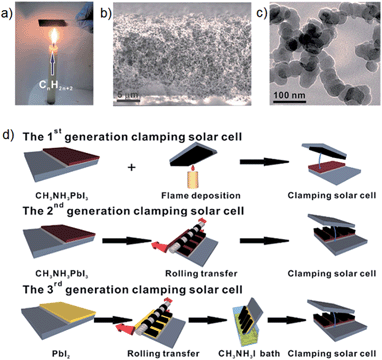 | ||
| Fig. 5 (a) Digital photo of the candle-soot film preparation. (b) Cross sectional SEM image of the candle-soot film. (c) TEM image of the as-prepared candle-soot particles. (d) Fabrication processes of the candle-soot film based PSCs. Reprinted from ref. 70. | ||
Li et al.69 first reported CNT networks as the counter electrode of PSC. A reasonable comparison was made by these authors by fabricating HTM-free PSCs based on only CNTs or only Au electrode. In the absence of organic HTMs, the efficiency of CNTs cathode employed cell was 6.87% which was far higher than that (5.14%) achieved by the Au based device. This impressive result indicates that the use of CNTs can outperform those precious metal based PSCs. Furthermore, the efficiency of the PSC fabricated with CNTs cathode was improved to be 9.9% by adding spiro-OMeTAD. In addition to this improvement, excellent development in this class of solar cells could be achieved by upgrading the CNT properties. For instance, the use of chirality sorted nanotubes to give separated metallic CNTs would bring a critical improvement in the PSC performance because it enhances the charge selectivity.74 Moreover, since chemically doped CNTs or graphene show excellent conductivity, they should exhibit very high charge extraction rate. Applying a chemical doping approach on the carbon nanomaterials could be promising way to further improve the solar cell performance.75
Very recently, the first fibre-shaped PSC was fabricated by Qiu et al.,71 who used stainless steel wires with a TiO2 compact layer and mesoporous layer as the anode, CH3NH3PbI3 perovskite as the sensitiser, spiro-OMeTAD as the HTM and transparent CNTs as the cathode. The advantage of the fiber-shaped PSCs is that they are a lightweight and flexible device. Indeed, this first fibre-shaped PSC exhibited a good Jsc (∼9.5 mA cm−2) and yielded an energy conversion efficiency of 3.3% after optimisation. These authors believed that this good Jsc resulted from the high electrical conductivity of CNTs that provided a rapid charge transport.
The idea of incorporating nanocarbons between the perovskite layer and mesoporous semiconducting oxide layer was first initiated by Snaith's group by applying a C60SAM upon the mesoporous TiO2 layer.85 They found that the C60SAM acts as a very effective electron acceptor from both the perovskite and P3HT polymer. It is also worth noting that in the presence of the C60SAM, direct electron transfer from the perovskite to the TiO2 is partially blocked and thus resulted in an improved Voc. This inhibition of electron transfer to the TiO2 was associated with the energy levels of the components (see inset of Fig. 7a) and poor electronic coupling. Moreover, UV-vis spectra of the films revealed that the addition of the C60SAM does not significantly influence the light absorption of the sensitiser, as shown in Fig. 7a. The charge transport of the TiO2 was enhanced 4–5 times after the incorporation of the C60SAM. Indeed, the PSCs fabricated in the presence of C60SAM (the device structure is shown in Fig. 7b) exhibited an energy conversion efficiency of 6.7%, which was nearly 2 times higher than that obtained by the benchmark cell (TiO2/perovskite/P3HT).
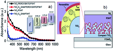 | ||
| Fig. 7 (a) UV-vis spectra of P3HT and perovskite films with and without C60SAM. Inset: the energy level of the components used in Snaith's work.85 (b) The structure of the PSC fabricated with C60SAM layer between perovskite and TiO2 layers. Reprinted with permission from ref. 85 © 2013, American Chemical Society. | ||
A second example is from Zhu et al.81 who synthesised single/few layer GQDs using an electrochemical method such as that illustrated in Fig. 8a and inserted them between the layers of perovskite and TiO2 nanoparticles. In their PSCs, the GQDs were proposed to serve as a bridge to facilitate electron injection from the perovskite to the TiO2 conduction band (see Fig. 8b drawn by these authors). However, as shown in Fig. 8b, the conduction band of the GQD (−4.2 eV) is lower than that of the TiO2 (−4.0 eV). If these energy levels are correct, it is not “downhill” in energy from the perovskite to the GQD to the TiO2 and hence rapid electron transfer would not seem feasible. However, the final PSC fabricated based on GQDs (Fig. 8c) exhibited a high PCE of 10.15% which was considerably higher than that of GQDs-free cell (8.81%). The authors showed that this significant improvement in the cell performance was associated with the much faster electron injection when GQDs are inserted in the cells. The injection time of electrons from the perovskite to the TiO2 conduction band was measured to be 260–307 ps using transient absorption spectroscopy. A significant improvement in the electron injection time (90–106 ps) was observed after adding GQDs between the perovskite and TiO2 layers (see Fig. 8d and e). Although the insertion of GQDs between the perovskite and TiO2 layers of PSCs has brought a significant improvement in the PV efficiency, the mechanism for this efficiency enhancement clearly needed to be investigated further. In addition, controlling the band gap structure of GQDs for effective electron injection would be a promising future research direction and likely to further improve efficiency of GQDs enhanced PSCs.
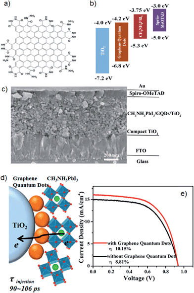 | ||
| Fig. 8 (a) Schematic of GQD structure. (b) Energy levels of different layers used in PSCs of Zhu et al.,81 (c) Cross sectional SEM image of PSCs fabricated with GQDs. (d) Schematic illustration of electron generation and injection at the interfaces of TiO2, GQDs and perovskites. (e) Current density–voltage curves for the best performing PSCs. Reprinted with permission from ref. 81 © 2014, American Chemical Society. | ||
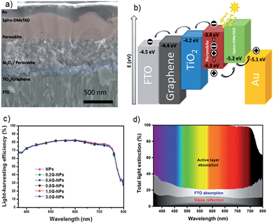 | ||
| Fig. 9 (a) Cross sectional SEM image of PSC architecture which achieved 15.6% efficiency by Wang et al.21 (b) Schematic illustration of energy levels that shows the work function of graphene is ideally suited for use in this solar cell. (c) Light harvesting efficiency spectra of PSCs as a function of graphene content in the blocking layer. (d) Cumulative light extinction in the low-temperature processed graphene-TiO2 layer based PSC. Reprinted with permission from ref. 21 © 2014, American Chemical Society. | ||
This study21 suggests that high-efficiency PV cells no longer require a high-temperature sintering process and graphene/TiO2 nanocomposite materials in PSCs meets the needs of large scale manufacture on a wide range of substrates including plastic films. Therefore, the authors of this review anticipate that many improvements can be made by applying further treatment to the graphene/TiO2 composite layers. For example, chemical doping is a powerful method to increase the conductivity of graphene.92 It is reasonable to expect improved performance by incorporating chemically doped graphene in the TiO2 blocking layers. In addition, CNTs and their well-aligned structures should also be applied in the electron collection layers as they have very unique 1D structure and high conductivity. Furthermore, nanocomposite structures based on graphene and/or CNT materials exhibit extraordinary properties and have been proven to be good candidates for energy applications.93–95 In particular, CNTs and graphene nanocomposites show special electrical, chemical, physical and catalytic properties. In this regard, the application of CNTs/graphene composites in the TiO2 blocking layer of PSCs would be an important research direction.
2.2 Possible applications of carbon materials in PSCs
Although CNTs, graphene and their derivatives have been extensively explored in recent years, there are very few reports on using carbon nanomaterials as a TCF for the DSSC window electrode.100–103 For example, Wei et al.101 reported the fabrication of SWCNTs based polyethylene terephthalate (PET) as a TCF for the DSSC photoelectrode. However, their SWCNTs/PET thin film based DSSC exhibited very poor energy conversion efficiency. Similarly, Kyaw et al.102 also showed that the DSSCs fabricated with the CNTs-TCF based photoelectrodes cannot achieve a good efficiency if no further surface modification is made. These poor efficiencies obtained by the DSSCs fabricated with carbon nanostructures based TCFs are mainly associated with the high catalytic activity of carbon materials for the dissociation of the chemicals involved in the DSSC redox electrolyte. A brief discussion on this phenomenon is as follows: When carbon materials are applied in the photoelectrode, the electrons (injected from the conduction band of semiconducting oxide) recombine with I3− in the electrolyte by the reaction I3− + 2e− → 3I−, at the electrolyte/photoelectrode interface. Of particular issue here is the limitation of electron transport from the carbon to the external circuit. So, it is difficult to use carbon based TCFs in the photoelectrode of liquid-type solar cells and alternatives should be pursued.
However, it may be possible that TCFs produced from carbon materials can be used as the TCF anode of PSCs because these cells consist of solid electrolyte. In this regard, applying carbon materials based TCFs in PSCs would be very valuable and this could open new avenues of investigation for the researchers leading to advancements such as flexible devices. Many approaches have been developed to improve the performance of CNTs and graphene based TCFs and they can be found in several recent contributions.97,98,104–106
3 Conclusion and perspectives
In this review, we discussed the progress on the application of carbon based nanomaterials in each aspect of state of the art mesoscopic PSCs. On the basis of recent advancements of PSCs, it is clear that carbon nanomaterials are promising candidates for the development of the PSCs due to their unique properties as well as low cost and abundance. Although excellent achievements have been made in the use of carbon materials in PSCs, this cutting-edge research field is still in its initial stage. Therefore, we expect that the following points will be carefully investigated in the future efforts of using nanocarbons in PSCs.(i) Carbonaceous materials have been proven to be ideal candidates to replace the precious metal in the cathode of PSCs. Nanocarbon films exhibit the added advantage that they can replace both the metal electrode and HTM. We believe that further improvement in this class of solar cells could be made by upgrading the CNT properties. For instance, the use of pure metallic CNTs would bring critical improvements in the performance of PSCs. Although carbon black and CNTs have been utilised as the PSC cathode, the use of graphene materials in this application is lacking despite graphene possessing higher electrical conductivity than the other forms of carbon. Therefore, reports on using graphene as the conductive cathode of PSCs would be worthwhile. Moreover, chemically doped CNTs and graphene should exhibit very high charge transfer rates. So, applying chemically doped CNTs and graphene in the counter electrode of PSCs would be a promising way to improve the cell performance. Furthermore, the authors of this review anticipate that composite materials based on carbon nanostructures (especially CNTs and graphene) will provide remarkable improvement in the performance of PSCs when they are used in the counter electrode.
(ii) It was found that the carbon materials play a critical role in improving the stability of PSCs. Therefore, additional treatments on CNTs and/or other types of carbon structures would bring significant enhancement. In addition to this, incorporating functionalised CNT structures with other polymers would be an important research direction for the long-term stability of PSCs especially in the hole-transporting layer. The application of graphene and their derivatives in the hole transporting layer of PSCs would be a promising future research direction.
(iii) Inserting GQDs between the perovskite and TiO2 layers of PSCs was found to be an effective method to improve the PV efficiency of PSCs although the exact mechanism of this improvement is unclear. It is likely that further improvements will be possible by adjusting the band gap of GQDs to optimise electron injection and transfer to the anode.
(iv) Application of graphene in the TiO2 blocking layer yielded significant improvement in the cell performance. It is well known that chemical doping is an effective approach to enhance the conductivity of graphene material. Based on this concept, improved performance by using chemically doped graphene in the TiO2 electron collection layers is very likely. In addition, graphene and CNT based composite materials exhibit unique electrical, chemical and physical properties as well as an excellent synergetic effect. For this reason, the use of CNTs/graphene composites in the TiO2 blocking layer of PSCs would be very valuable for high-performance device.
(v) There is still valuable and important work to be done by exploring the incorporation of carbon materials in the front transparent conductive layer and the mesoporous oxide layer of PSCs. This research would have the potential to further improve the efficiencies and stability of the PSC system.
Acknowledgements
The support of the Australian Research Council Discovery Program (DP130101714) is gratefully acknowledged. Munkhbayar Batmunkh acknowledges International Postgraduate Research Scholarship (IPRS) and Australian Postgraduate Award (APA) for their financial support during his study in Australia.Notes and references
- R. F. Service, Science, 2005, 309, 548–551 CrossRef CAS PubMed.
- L. M. Goncalves, V. de Zea Bermudez, H. A. Ribeiro and A. M. Mendes, Energy Environ. Sci., 2008, 1, 655–667 CAS.
- L. Wang, H. Liu, R. M. Konik, J. A. Misewich and S. S. Wong, Chem. Soc. Rev., 2013, 42, 8134–8156 RSC.
- B. O'Regan and M. Gratzel, Nature, 1991, 353, 737–740 CrossRef.
- G. Yu, J. Gao, J. C. Hummelen, F. Wudl and A. J. Heeger, Science, 1995, 270, 1789–1791 CAS.
- M. T. Winkler, W. Wang, O. Gunawan, H. J. Hovel, T. K. Todorov and D. B. Mitzi, Energy Environ. Sci., 2014, 7, 1029–1036 Search PubMed.
- K. W. J. Barnham and G. Duggan, J. Appl. Phys., 1990, 67, 3490–3493 CrossRef CAS PubMed.
- S. Mathew, A. Yella, P. Gao, R. Humphry-Baker, F. E. CurchodBasile, N. Ashari-Astani, I. Tavernelli, U. Rothlisberger, K. NazeeruddinMd and M. Grätzel, Nat. Chem., 2014, 6, 242–247 CrossRef CAS PubMed.
- O. Adebanjo, P. P. Maharjan, P. Adhikary, M. Wang, S. Yang and Q. Qiao, Energy Environ. Sci., 2013, 6, 3150–3170 CAS.
- C.-C. Chen, W.-H. Chang, K. Yoshimura, K. Ohya, J. You, J. Gao, Z. Hong and Y. Yang, Adv. Mater., 2014, 26, 5670–5677 CrossRef CAS PubMed.
- W. Wang, M. T. Winkler, O. Gunawan, T. Gokmen, T. K. Todorov, Y. Zhu and D. B. Mitzi, Adv. Energy Mater., 2014, 4, 1301465 Search PubMed.
- C.-H. M. Chuang, P. R. Brown, V. Bulović and M. G. Bawendi, Nat. Mater., 2014, 13, 796–801 CrossRef CAS PubMed.
- J. Burschka, N. Pellet, S.-J. Moon, R. Humphry-Baker, P. Gao, M. K. Nazeeruddin and M. Gratzel, Nature, 2013, 499, 316–319 CrossRef CAS PubMed.
- A. Kojima, K. Teshima, Y. Shirai and T. Miyasaka, J. Am. Chem. Soc., 2009, 131, 6050–6051 CrossRef CAS PubMed.
- J.-H. Im, C.-R. Lee, J.-W. Lee, S.-W. Park and N.-G. Park, Nanoscale, 2011, 3, 4088–4093 RSC.
- H.-S. Kim, C.-R. Lee, J.-H. Im, K.-B. Lee, T. Moehl, A. Marchioro, S.-J. Moon, R. Humphry-Baker, J.-H. Yum, J. E. Moser, M. Gratzel and N.-G. Park, Sci. Rep., 2012, 2, 591 Search PubMed.
- M. M. Lee, J. Teuscher, T. Miyasaka, T. N. Murakami and H. J. Snaith, Science, 2012, 338, 643–647 CrossRef CAS PubMed.
- J. H. Heo, S. H. Im, J. H. Noh, T. N. Mandal, C.-S. Lim, J. A. Chang, Y. H. Lee, H.-j. Kim, A. Sarkar, K. NazeeruddinMd, M. Gratzel and S. I. Seok, Nat. Photonics, 2013, 7, 486–491 CrossRef CAS.
- J. H. Noh, S. H. Im, J. H. Heo, T. N. Mandal and S. I. Seok, Nano Lett., 2013, 13, 1764–1769 CAS.
- M. Liu, M. B. Johnston and H. J. Snaith, Nature, 2013, 501, 395–398 CrossRef CAS PubMed.
- J. T.-W. Wang, J. M. Ball, E. M. Barea, A. Abate, J. A. Alexander-Webber, J. Huang, M. Saliba, I. Mora-Sero, J. Bisquert, H. J. Snaith and R. J. Nicholas, Nano Lett., 2013, 14, 724–730 CrossRef PubMed.
- S. Ryu, J. H. Noh, N. J. Jeon, Y. Chan Kim, W. S. Yang, J. Seo and S. I. Seok, Energy Environ. Sci., 2014, 7, 2614–2618 CAS.
- N. J. Jeon, J. H. Noh, Y. C. Kim, W. S. Yang, S. Ryu and S. I. Seok, Nat. Mater., 2014, 13, 897–903 CrossRef CAS PubMed.
- H. Zhou, Q. Chen, G. Li, S. Luo, T.-b. Song, H.-S. Duan, Z. Hong, J. You, Y. Liu and Y. Yang, Science, 2014, 345, 542–546 CrossRef CAS PubMed.
- P. P. Boix, K. Nonomura, N. Mathews and S. G. Mhaisalkar, Mater. Today, 2014, 17, 16–23 CrossRef CAS PubMed.
- T. C. Sum and N. Mathews, Energy Environ. Sci., 2014, 7, 2518–2534 CAS.
- P. Gao, M. Gratzel and M. K. Nazeeruddin, Energy Environ. Sci., 2014, 7, 2448–2463 CAS.
- N.-G. Park, J. Phys. Chem. Lett., 2013, 4, 2423–2429 CrossRef CAS.
- N.-G. Park, Mater. Today, 2015, 18, 65–72 CrossRef CAS PubMed.
- G. Hodes, Science, 2013, 342, 317–318 CrossRef CAS PubMed.
- M. A. Green, A. Ho-Baillie and H. J. Snaith, Nat. Photonics, 2014, 8, 506–514 CrossRef CAS.
- P. Docampo, S. Guldin, T. Leijtens, N. K. Noel, U. Steiner and H. J. Snaith, Adv. Mater., 2014, 26, 4013–4030 CrossRef CAS PubMed.
- H. J. Snaith, J. Phys. Chem. Lett., 2013, 4, 3623–3630 CrossRef CAS.
- B. V. Lotsch, Angew. Chem., Int. Ed., 2014, 53, 635–637 CrossRef CAS PubMed.
- S. Luo and W. A. Daoud, J. Mater. Chem. A, 2015 10.1039/c1034ta04953e.
- M. He, D. Zheng, M. Wang, C. Lin and Z. Lin, J. Mater. Chem. A, 2014, 2, 5994–6003 CAS.
- X. Fan, M. Zhang, X. Wang, F. Yang and X. Meng, J. Mater. Chem. A, 2013, 1, 8694–8709 CAS.
- N. G. Sahoo, Y. Pan, L. Li and S. H. Chan, Adv. Mater., 2012, 24, 4203–4210 CrossRef CAS.
- D. Wei and J. Kivioja, Nanoscale, 2013, 5, 10108–10126 RSC.
- L. J. Brennan, M. T. Byrne, M. Bari and Y. K. Gun'ko, Adv. Energy Mater., 2011, 1, 472–485 CrossRef CAS.
- J. Du, S. Pei, L. Ma and H.-M. Cheng, Adv. Mater., 2014, 26, 1958–1991 CrossRef CAS PubMed.
- C. J. Shearer, A. Cherevan and D. Eder, Adv. Mater., 2014, 26, 2295–2318 CrossRef CAS PubMed.
- D. D. Tune, B. S. Flavel, R. Krupke and J. G. Shapter, Adv. Energy Mater., 2012, 2, 1043–1055 CrossRef CAS.
- X. Zhou, J. Qiao, L. Yang and J. Zhang, Adv. Energy Mater., 2014, 4, 1301523 Search PubMed.
- Z. Yin, J. Zhu, Q. He, X. Cao, C. Tan, H. Chen, Q. Yan and H. Zhang, Adv. Energy Mater., 2014, 4, 1300574 Search PubMed.
- Q. Li, R. Cao, J. Cho and G. Wu, Adv. Energy Mater., 2014, 4, 1301415 Search PubMed.
- R. D. Costa, F. Lodermeyer, R. Casillas and D. M. Guldi, Energy Environ. Sci., 2014, 7, 1281–1296 CAS.
- J. D. Roy-Mayhew and I. A. Aksay, Chem. Rev., 2014, 114, 6323–6348 CrossRef CAS PubMed.
- H. Wang and Y. H. Hu, Energy Environ. Sci., 2012, 5, 8182–8188 CAS.
- J. L. Xie, C. X. Guo and C. M. Li, Energy Environ. Sci., 2014, 7, 2559–2579 CAS.
- J.-K. Sun and Q. Xu, Energy Environ. Sci., 2014, 7, 2071–2100 CAS.
- X. Cao, Z. Yin and H. Zhang, Energy Environ. Sci., 2014, 7, 1850–1865 CAS.
- Y.-Y. Lai, Y.-J. Cheng and C.-S. Hsu, Energy Environ. Sci., 2014, 7, 1866–1883 CAS.
- D. Jariwala, V. K. Sangwan, L. J. Lauhon, T. J. Marks and M. C. Hersam, Chem. Soc. Rev., 2013, 42, 2824–2860 RSC.
- X. Huang, X. Qi, F. Boey and H. Zhang, Chem. Soc. Rev., 2012, 41, 666–686 RSC.
- S. Hwang, M. Batmunkh, M. J. Nine, H. Chung and H. Jeong, ChemPhysChem, 2015, 16, 53–65 CrossRef CAS PubMed.
- T. Chen and L. Dai, J. Mater. Chem. A, 2014, 2, 10756–10775 CAS.
- J.-Y. Jeng, Y.-F. Chiang, M.-H. Lee, S.-R. Peng, T.-F. Guo, P. Chen and T.-C. Wen, Adv. Mater., 2013, 25, 3727–3732 CrossRef CAS PubMed.
- Q. Wang, Y. Shao, Q. Dong, Z. Xiao, Y. Yuan and J. Huang, Energy Environ. Sci., 2014, 7, 2359–2365 CAS.
- Y. Shao, Z. Xiao, C. Bi, Y. Yuan and J. Huang, Nat. Commun., 2014, 5, 5784 CrossRef PubMed.
- Z. Wu, S. Bai, J. Xiang, Z. Yuan, Y. Yang, W. Cui, X. Gao, Z. Liu, Y. Jin and B. Sun, Nanoscale, 2014, 6, 10505–10510 RSC.
- Q. Xue, Z. Hu, J. Liu, J. Lin, C. Sun, Z. Chen, C. Duan, J. Wang, C. Liao, W. M. Lau, F. Huang, H.-L. Yip and Y. Cao, J. Mater. Chem. A, 2014, 2, 19598–19603 CAS.
- J.-S. Yeo, R. Kang, S. Lee, Y.-J. Jeon, N. Myoung, C.-L. Lee, D.-Y. Kim, J.-M. Yun, Y.-H. Seo, S.-S. Kim and S.-I. Na, Nano Energy, 2015, 12, 96–104 CrossRef CAS PubMed.
- Z. Ku, Y. Rong, M. Xu, T. Liu and H. Han, Sci. Rep., 2013, 3, 3132 Search PubMed.
- Y. Rong, Z. Ku, A. Mei, T. Liu, M. Xu, S. Ko, X. Li and H. Han, J. Phys. Chem. Lett., 2014, 5, 2160–2164 CrossRef CAS.
- F. Zhang, X. Yang, H. Wang, M. Cheng, J. Zhao and L. Sun, ACS Appl. Mater. Interfaces, 2014, 6, 16140–16146 CAS.
- L. Zhang, T. Liu, L. Liu, M. Hu, Y. Yang, A. Mei and H. Han, J. Mater. Chem. A, 2015 10.1039/c1034ta04647a.
- A. Mei, X. Li, L. Liu, Z. Ku, T. Liu, Y. Rong, M. Xu, M. Hu, J. Chen, Y. Yang, M. Grätzel and H. Han, Science, 2014, 345, 295–298 CrossRef CAS PubMed.
- Z. Li, S. A. Kulkarni, P. P. Boix, E. Shi, A. Cao, K. Fu, S. K. Batabyal, J. Zhang, Q. Xiong, L. H. Wong, N. Mathews and S. G. Mhaisalkar, ACS Nano, 2014, 8, 6797–6804 CrossRef CAS PubMed.
- Z. Wei, K. Yan, H. Chen, Y. Yi, T. Zhang, X. Long, J. Li, L. Zhang, J. Wang and S. Yang, Energy Environ. Sci., 2014, 7, 3326–3333 CAS.
- L. Qiu, J. Deng, X. Lu, Z. Yang and H. Peng, Angew. Chem., Int. Ed., 2014, 53, 10425–10428 CrossRef CAS PubMed.
- M. Xu, Y. Rong, Z. Ku, A. Mei, T. Liu, L. Zhang, X. Li and H. Han, J. Mater. Chem. A, 2014, 2, 8607–8611 CAS.
- M. Hu, L. Liu, A. Mei, Y. Yang, T. Liu and H. Han, J. Mater. Chem. A, 2014, 2, 17115–17121 CAS.
- M. S. Arnold, A. A. Green, J. F. Hulvat, S. I. Stupp and M. C. Hersam, Nat. Nanotechnol., 2006, 1, 60–65 CrossRef CAS PubMed.
- D. D. Tune, F. Hennrich, S. Dehm, M. F. G. Klein, K. Glaser, A. Colsmann, J. G. Shapter, U. Lemmer, M. M. Kappes, R. Krupke and B. S. Flavel, Adv. Energy Mater., 2013, 3, 1091–1097 CrossRef CAS.
- F. Fabregat-Santiago, J. Bisquert, L. Cevey, P. Chen, M. Wang, S. M. Zakeeruddin and M. Grätzel, J. Am. Chem. Soc., 2008, 131, 558–562 CrossRef PubMed.
- A. Abate, T. Leijtens, S. Pathak, J. Teuscher, R. Avolio, M. E. Errico, J. Kirkpatrik, J. M. Ball, P. Docampo, I. McPherson and H. J. Snaith, Phys. Chem. Chem. Phys., 2013, 15, 2572–2579 RSC.
- J. Burschka, A. Dualeh, F. Kessler, E. Baranoff, N.-L. Cevey-Ha, C. Yi, M. K. Nazeeruddin and M. Grätzel, J. Am. Chem. Soc., 2011, 133, 18042–18045 CrossRef CAS PubMed.
- S. N. Habisreutinger, T. Leijtens, G. E. Eperon, S. D. Stranks, R. J. Nicholas and H. J. Snaith, Nano Lett., 2014, 14, 5561–5568 CrossRef CAS PubMed.
- S. Iijima, Nature, 1991, 354, 56–58 CrossRef CAS.
- Z. Zhu, J. Ma, Z. Wang, C. Mu, Z. Fan, L. Du, Y. Bai, L. Fan, H. Yan, D. L. Phillips and S. Yang, J. Am. Chem. Soc., 2014, 136, 3760–3763 CrossRef CAS PubMed.
- G. Xing, N. Mathews, S. Sun, S. S. Lim, Y. M. Lam, M. Grätzel, S. Mhaisalkar and T. C. Sum, Science, 2013, 342, 344–347 CrossRef CAS PubMed.
- K. J. Williams, C. A. Nelson, X. Yan, L.-S. Li and X. Zhu, ACS Nano, 2013, 7, 1388–1394 CrossRef CAS PubMed.
- Z. Zhang, J. Zhang, N. Chen and L. Qu, Energy Environ. Sci., 2012, 5, 8869–8890 CAS.
- A. Abrusci, S. D. Stranks, P. Docampo, H.-L. Yip, A. K. Y. Jen and H. J. Snaith, Nano Lett., 2013, 13, 3124–3128 CrossRef CAS PubMed.
- Y. Hernandez, V. Nicolosi, M. Lotya, F. M. Blighe, Z. Sun, S. De, I. T. McGovern, B. Holland, M. Byrne, Y. K. Gun'Ko, J. J. Boland, P. Niraj, G. Duesberg, S. Krishnamurthy, R. Goodhue, J. Hutchison, V. Scardaci, A. C. Ferrari and J. N. Coleman, Nat. Nanotechnol., 2008, 3, 563–568 CrossRef CAS PubMed.
- A. O'Neill, U. Khan, P. N. Nirmalraj, J. Boland and J. N. Coleman, J. Phys. Chem. C, 2011, 115, 5422–5428 Search PubMed.
- K. S. Novoselov, A. K. Geim, S. V. Morozov, D. Jiang, Y. Zhang, S. V. Dubonos, I. V. Grigorieva and A. A. Firsov, Science, 2004, 306, 666–669 CrossRef CAS PubMed.
- K. S. Novoselov, A. K. Geim, S. V. Morozov, D. Jiang, M. I. Katsnelson, I. V. Grigorieva, S. V. Dubonos and A. A. Firsov, Nature, 2005, 438, 197–200 CrossRef CAS PubMed.
- A. K. Geim and K. S. Novoselov, Nat. Mater., 2007, 6, 183–191 CrossRef CAS PubMed.
- R. R. Nair, P. Blake, A. N. Grigorenko, K. S. Novoselov, T. J. Booth, T. Stauber, N. M. R. Peres and A. K. Geim, Science, 2008, 320, 1308 CrossRef CAS PubMed.
- F. Schedin, A. K. Geim, S. V. Morozov, E. W. Hill, P. Blake, M. I. Katsnelson and K. S. Novoselov, Nat. Mater., 2007, 6, 652–655 CrossRef CAS PubMed.
- Y. Sun, Q. Wu and G. Shi, Energy Environ. Sci., 2011, 4, 1113–1132 CAS.
- D. Chen, H. Zhang, Y. Liu and J. Li, Energy Environ. Sci., 2013, 6, 1362–1387 CAS.
- H. Chang and H. Wu, Energy Environ. Sci., 2013, 6, 3483–3507 CAS.
- K. Ellmer, Nat. Photonics, 2012, 6, 809–817 CrossRef CAS.
- S. Roth and H. J. Park, Chem. Soc. Rev., 2010, 39, 2477–2483 RSC.
- L. Hu, D. S. Hecht and G. Grüner, Chem. Rev., 2010, 110, 5790–5844 CrossRef CAS PubMed.
- J. K. Wassei and R. B. Kaner, Mater. Today, 2010, 13, 52–59 CrossRef CAS.
- X. Wang, L. Zhi and K. Müllen, Nano Lett., 2007, 8, 323–327 CrossRef PubMed.
- D. Wei, H. S. Unalan, D. Han, Q. Zhang, L. Niu, G. Amaratunga and T. Ryhanen, Nanotechnology, 2008, 19, 424006 CrossRef PubMed.
- A. K. K. Kyaw, H. Tantang, T. Wu, L. Ke, C. Peh, Z. H. Huang, X. T. Zeng, H. V. Demir, Q. Zhang and X. W. Sun, Appl. Phys. Lett., 2011, 99, 021107 CrossRef PubMed.
- J. Du, F. Bittner, D. S. Hecht, C. Ladous, J. Ellinger, T. Oekermann and M. Wark, Thin Solid Films, 2013, 531, 391–397 CrossRef CAS PubMed.
- D. S. Hecht, L. Hu and G. Irvin, Adv. Mater., 2011, 23, 1482–1513 CrossRef CAS PubMed.
- Q. Zheng, Z. Li, J. Yang and J.-K. Kim, Prog. Mater. Sci., 2014, 64, 200–247 CrossRef CAS PubMed.
- S. B. Yang, B.-S. Kong, D.-H. Jung, Y.-K. Baek, C.-S. Han, S.-K. Oh and H.-T. Jung, Nanoscale, 2011, 3, 1361–1373 RSC.
- J.-Y. Jeng, K.-C. Chen, T.-Y. Chiang, P.-Y. Lin, T.-D. Tsai, Y.-C. Chang, T.-F. Guo, P. Chen, T.-C. Wen and Y.-J. Hsu, Adv. Mater., 2014, 26, 4107–4113 CrossRef CAS PubMed.
- T. Leijtens, G. E. Eperon, S. Pathak, A. Abate, M. M. Lee and H. J. Snaith, Nat. Commun., 2013, 4, 2885 Search PubMed.
- M. H. Kumar, N. Yantara, S. Dharani, M. Graetzel, S. Mhaisalkar, P. P. Boix and N. Mathews, Chem. Commun., 2013, 49, 11089–11091 RSC.
- K. Mahmood, B. S. Swain, A. R. Kirmani and A. Amassian, J. Mater. Chem. A, 2015 10.1039/c1034ta04883k.
- D. Bi, S.-J. Moon, L. Haggman, G. Boschloo, L. Yang, E. M. J. Johansson, M. K. Nazeeruddin, M. Gratzel and A. Hagfeldt, RSC Adv., 2013, 3, 18762–18766 RSC.
- K.-C. Wang, J.-Y. Jeng, P.-S. Shen, Y.-C. Chang, E. W.-G. Diau, C.-H. Tsai, T.-Y. Chao, H.-C. Hsu, P.-Y. Lin, P. Chen, T.-F. Guo and T.-C. Wen, Sci. Rep., 2014, 4, 4756 Search PubMed.
- A. K. Chandiran, M. Abdi-Jalebi, M. K. Nazeeruddin and M. Grätzel, ACS Nano, 2014, 8, 2261–2268 CrossRef CAS PubMed.
- M. Batmunkh, M. J. Biggs and J. G. Shapter, Adv. Sci., 2015, 2, 201400025 Search PubMed.
| This journal is © The Royal Society of Chemistry 2015 |


