Asymmetric axonal edge guidance: a new paradigm for building oriented neuronal networks†
Renaud
Renault
abc,
Jean-Baptiste
Durand
abc,
Jean-Louis
Viovy
abc and
Catherine
Villard
*abc
aUMR 168 Physico-Chimie Curie, CNRS, PSL Research University, Institut Curie, 75005, Paris, France. E-mail: catherine.villard@curie.fr
bUPMC, Sorbonne Universités, 75006, Paris, France
cInstitut Pierre-Gilles de Gennes pour la Microfluidique, 75005, Paris, France
First published on 10th May 2016
Abstract
We present a novel kind of directional axon guides for brain-on-a-chip applications. Contrarily to previous works, the directionality in our design is created by rerouting axons growing in the unwanted direction back to their original compartment while leaving the other growth direction unaffected. This design yields state-of-the-art levels of directionality without the disadvantages of previously reported technologies.
In vitro reconstruction of neural circuits represents an interesting alternative to animal models or brain slices, and microfluidics has emerged as an important technology to that end. The connectivity between neurons in microfluidic chips is usually controlled using microchannels that physically allow axons to grow and connect different populations of neurons while keeping the somas and dendrites in their respective compartments.1 In numerous cases, it is desirable to have unidirectional connections between neuronal populations, for instance, in order to recreate specific neural pathways involved in neurodegenerative diseases2 or to create functional neuronal devices.3 Several active methods using light,4 chemical gradients,5 or dielectrophoretic forces6 exist. However, these techniques are costly in terms of manufacturing time and instrumentation, and require synchronization of stimuli with axonal development, making experiment parallelization difficult. An alternative consists of using only geometrical constraints to passively control the direction of axonal growth.7,8
So far, the most characterized and efficient design consists of tapered microchannels, acting like axon diodes. It uses the differential entrance probability of axons at either the wide or the narrow opening of the channels to promote unidirectional connectivity.7 Yet, the efficiency of this design critically depends on the width of the narrow side which cannot be reduced below a critical size without important drawbacks, such as difficult and irreproducible micro-fabrication, limited axonal transmission in the desired direction leading to a lower overall connectivity, restricted access of diffusive factors through the channels and mechanical constriction, compromising long-term axonal integrity.
We propose in this paper a completely new axon diode design which yields state-of-the-art direction selectivity without the inherent drawbacks of tapered channels. Our approach stems from the observation that (1) cortical axons tend to grow along the edges (dihedral junctions between horizontal and vertical walls) of 3D guiding microstructures, and that (2) they escape this guidance if the edge's direction changes too abruptly, due to their non-zero bending stiffnesses.9,10 In our design, we implemented a selective “return to sender” strategy by exploiting this phenomenon, redirecting axons growing in the unwanted “reverse” direction to their original compartment via U-shaped lateral connections. We quantitatively evaluated the efficiencies of different variations of this basic concept regarding their direction selectivity, and demonstrated that they constitute a major improvement over the tapered channels already used by the brain-on-a-chip community.2,7,11,12
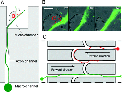
Over the course of different experiments using PDMS microchips, we observed that cortical axons tend to follow the edges of microstructures in a very consistent manner. In order to explore this phenomenon in more detail, PDMS sectors (radius 30 μm) with various angles (Fig. 1A and B) were used to determine the preferred trajectories of cortical axons (see Experimental section†) initially growing along the edges of microstructures when they experience an abrupt change in direction α. Our results show that edge guidance predominates when α ≤ 26°. In contrast, a straight axonal trajectory prevails over edge guidance when α ≤ 84°. These observations were used to control the directionality of axonal flow. Our design is based on straight channels with uniform width (10 μm) and height (5 μm) connecting two chambers, similar to the original microchannels.1 However, in this new design, the channels are interconnected by curved microchannels (arches). Upon arriving at a bifurcation, axons following the edges of the channels in the reverse direction experience a smooth change of orientation and are expected to keep following the edges inside the arches to be progressively diverted into the adjacent channel and make U-turns towards their original chamber (Fig. 1C, red axon). Conversely, axons emitted in the forward direction experience instead an acute cusp. In this case, axons are expected to be released from the edges and resume their trajectories in the same straight microchannel after the junction (green axon).
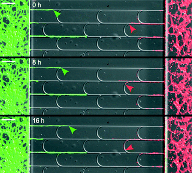
A clear demonstration of these two behaviors is shown in Fig. 2 and Movie S1.† Notice that the positions of the arches were shifted relatively to one another to firmly redirect the axons in the main channels. In designs involving unshifted arches, some axons achieved lateral escape along juxtaposed arches (see Movie S2†).
In order to assess the filtering capabilities of our designs quantitatively, and given the difficulty to count tightly packed axons growing inside the microstructures, we used fluorescent neurons (extracted from tdTomato mice; details of the experimental procedures and ethical approval are provided in the ESI†) to readily estimate the number of axons in different areas, assumed to be proportional to the associated fluorescence intensities. Although this particular staining is not specific for axons, previous studies have shown that dendrites are found only in the proximal part of guiding structures and that only axons remain past a few tens of microns,13 leaving very little doubt on the axonal nature of the neurites present in the terminal segments of our microchannels. Axonal transmission used in our quantification method was calculated for each microchannel by normalizing the fluorescence intensity in the terminal segment to the fluorescence in the associated somatodendritic compartments (see Experimental section†). The direction selectivity coefficient for each design was defined as the ratio between the average forward and reverse axonal transmission. Note that in order to minimize the variability in soma densities and other hidden variables that could distort the comparison between forward and reverse transmission, we designed each PDMS chip to present both orientations to a shared neuronal compartment.
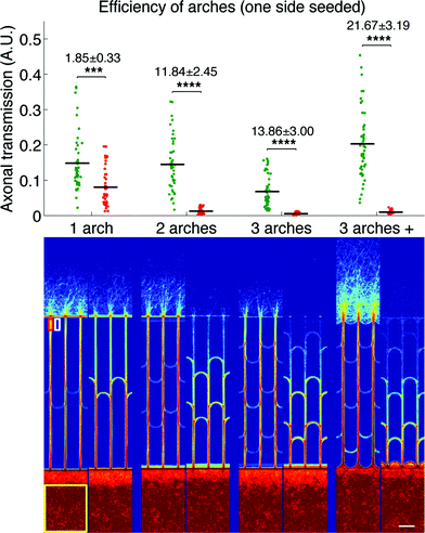
We first evaluated the filtering capabilities of different variations of our design in a simple case study where only one side was seeded, similarly to the protocols used for previous design characterization.7 The direction selectivity was evaluated for designs with one, two and three stages of arches, as well as a variation of the three-stage geometry where, in addition to the arches inside the microchannels, the edges of the neuronal compartments between the microchannels openings were arched as well. This particular design will be referred to as the “3 arches +” pattern in the remainder of the article. Fig. 3 presents the results obtained for the different designs, both as a graph (top) presenting the whole distribution of axonal transmission in the forward (green) and reverse (red) directions, and a visual representation (bottom) displaying an average intensity map of axonal density.
We observed a clear reduction of axonal transmission in the reverse direction as the number of arches increased, down to almost undetectable levels in the particular cases of 3 arches and 3 arches + patterns. In agreement with this observation, the axonal intensity inside the microchannels decreased by steps at each layer of arches, expressing the fact that more and more axons are filtered at each stage. Although forward transmission was slightly decreased by the introduction of additional layers of arches, the selectivity, most importantly, kept increasing (1.85 ± 0.33, 11.84 ± 2.45 and 13.86 ± 3.00 for the 1, 2 and 3 arches geometries, respectively). Strikingly, forward axonal transmission significantly increased (p > 0.0001) in the 3 arches + patterns in comparison to the 3 arches patterns, while axonal transmission in the reverse direction remained low. Our explanation is that the curved walls in contact with the emitting population act as funnels, guiding axons towards the entrance of the microchannels, while they act as deflectors in the reverse direction. This configuration, combining improved axonal collection on the forward entry side and axonal diversion on the opposite side, consequently reaches the striking directional selectivity of 21.67 ± 3.19. In regard to previous technologies, the 3 arches + design gives state-of-the-art performance, with less than 5% reverse growth and without the drawbacks of tapered diodes, or geometrical constrictions in general.7,8
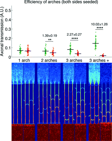
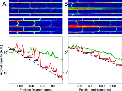
We then measured the performances of our microchannel designs in directionally connecting two neuronal populations by seeding non-fluorescent neurons in the second chamber. As in the former case, Fig. 4 provides a plot of axonal transmission distributions as well as a visual representation of the filtering effect of arches. Similar to the one-side-seeded case, the selectivity increased with the number of arches, with the 3 arches + configuration yielding the highest selectivity (10.02 ± 1.26). The major difference with the one-population-case was the increase of axonal transmission in the reverse direction, which impaired the filtering power of the arches. The intensity profiles in Fig. 5 show indeed that the fraction of axons making U-turns after each layer is reduced from about 63% (A), when one side is seeded, to about 47% (B), when both sides are seeded.
This reduction in selectivity can be explained by the interfering guidance cues provided by axons growing in the opposite direction. In line with this, note how stalling and/or branching of axons (illustrated in Fig. S3†), revealed by the peaks in the density profiles in Fig. 5, are less pronounced when both sides are seeded. Since stalling and branching are due to the lack of guiding cues,14 the reduction of the peaks matches well with the hypothesis that axons growing in the opposite direction provide additional guiding cues. In spite of this phenomenon, a selectivity of 90% was attainable, and it could be increased further simply by using additional layers of arches.
Conclusions
We showed that unidirectional axonal projections between neuronal populations grown inside microfluidic chips can be obtained using a novel microchannel geometry, which exploits edge guidance to operate an efficient and selective rerouting of axons growing in the unwanted direction. In addition, the elementary units (arches) can easily be stacked together in order to create tailored levels of directionality. This strategy does not necessitate the use of extremely narrow7 or innerly structured8 microchannels. Consequently, our approach offers easier microfabrication, higher axonal transmission, and better diffusion of possibly important molecules in the axon channels. Besides the important implications of these axon diodes for the reconstruction of oriented neural pathways, the original concepts of edge guidance and critical release angle could be developed into many other practical applications and benefit the growing brain-on-a-chip community far beyond the proof of concept provided by this particular study.Acknowledgements
We thank Daniela Vijgnevijc from the Curie Institute for providing us with the tdTomato mice, Pablo Vargas and Ana-Maria Lennon for providing us with the GFP LifeAct mice, Isabelle Grandjean and Manon Chartier from the Animal Facility of the Curie Institute for their crucial support for mice. This work was performed in part in the microfabrication cleanroom of the Institut Pierre-Gilles de Gennes. This work was supported by ERA-Net NEURON (MICRODEG), the Neuroscreen ANR project, European Research Council Advanced Grant No. 321107 “CellO”, ANR Investissement d'Avenir, and the IPGG Labex and Equipex.References
- J. W. Park, B. Vahidi, A. M. Taylor, S. W. Rhee and N. L. Jeon, Nat. Protoc., 2006, 1, 2128–2136 CrossRef CAS PubMed.
- B. Deleglise, S. Magnifico, E. Duplus, P. Vaur, V. Soubeyre, M. Belle, M. Vignes, J.-L. Viovy, E. Jacotot, J.-M. Peyrin and B. Brugg, Acta Neuropathol. Commun., 2014, 2, 145 Search PubMed.
- O. Feinerman, A. Rotem and E. Moses, Nat. Phys., 2008, 4, 967–973 CrossRef CAS.
- A. Ehrlicher, T. Betz, B. Stuhrmann, D. Koch, V. Milner, M. G. Raizen and J. Kas, Proc. Natl. Acad. Sci. U. S. A., 2002, 99, 16024–16028 CrossRef CAS PubMed.
- I. Dupin, L. Lokmane, M. Dahan, S. Garel and V. Studer, Neural Dev., 2015, 10, 5 CrossRef PubMed.
- T. Honegger, M. A. Scott, M. F. Yanik and J. Voldman, Lab Chip, 2013, 13, 589–598 RSC.
- J.-M. Peyrin, B. Deleglise, L. Saias, M. Vignes, P. Gougis, S. Magnifico, S. Betuing, M. Pietri, J. Caboche, P. Vanhoutte, J.-L. Viovy and B. Brugg, Lab Chip, 2011, 11, 3663–3673 RSC.
- J. le Feber, W. Postma, E. de Weerd, M. Weusthof and W. L. C. Rutten, Front. Neurosci., 2015, 9, 412 Search PubMed.
- R. M. Smeal, R. Rabbitt, R. Biran and P. A. Tresco, Ann. Biomed. Eng., 2005, 33, 376–382 CrossRef PubMed.
- S. Roth, G. Bugnicourt, M. Bisbal, S. Gory-Faure, J. Brocard and C. Villard, Small, 2012, 8, 671–675 CrossRef CAS PubMed.
- J. W. Park, H. J. Kim, M. W. Kang and N. L. Jeon, Lab Chip, 2013, 13, 509–521 RSC.
- R. Renault, N. Sukenik, S. Descroix, L. Malaquin, J.-L. Viovy, J.-M. Peyrin, S. Bottani, P. Monceau, E. Moses and M. Vignes, PLoS One, 2015, 10, e0120680 Search PubMed.
- A. Yamada, M. Vignes, C. Bureau, A. Mamane, B. Venzac, S. Descroix, J.-L. Viovy, C. Villard, J.-M. Peyrin and L. Malaquin, Lab Chip, 2016 10.1039/C6LC00414H.
- G. Gallo, Dev. Neurobiol., 2011, 71, 201–220 CrossRef PubMed.
Footnote |
| † Electronic supplementary information (ESI) available. See DOI: 10.1039/c6lc00479b |
| This journal is © The Royal Society of Chemistry 2016 |

