Three dimensional nitrogen-doped graphene hydrogels with in situ deposited cobalt phosphate nanoclusters for efficient oxygen evolution in a neutral electrolyte†
Anthony
Vasileff‡
,
Sheng
Chen‡
and
Shi Zhang
Qiao
*
School of Chemical Engineering, University of Adelaide, Adelaide, SA 5005, Australia. E-mail: s.qiao@adelaide.edu.au; Fax: +61 8 83034373; Tel: +61 8 83136443
First published on 11th August 2015
Abstract
A hybrid electrode of cobalt phosphate (CoPi) on nitrogen doped graphene hydrogels was fabricated by hydrothermal treatment of graphene oxide followed by CoPi electrodeposited in situ, which showed excellent performance toward oxygen reaction in a neutral electrolyte.
Conceptual insightsUsing electricity produced by renewable resources for the electrochemical splitting of water is considered the cleanest and most sustainable way to produce hydrogen fuel. However, one of the challenges of this process is to develop efficient catalysts for water oxidation, which is the half reaction of water-splitting, 2H2O → O2 + 4H+ + 4e−. In particular, catalysts which can function in a neutral electrolyte for water oxidation are attractive because they (1) offer simple fuel cell design, (2) operate under ambient conditions and (3) are less susceptible to CO2 poisoning. However, most reported catalysts are deactivated in a neutral electrolyte. Here a facile synthesis of a catalyst formed by in situ electrodeposition of cobalt phosphate onto three-dimensional (3D) nitrogen doped graphene hydrogels, which demonstrated excellent catalytic performance in a neutral electrolyte, is presented. The reason for the good performance of such material may be the synergistic effect between cobalt phosphate nanoclusters and the N-doped graphene hydrogel substrate. On one hand, cobalt phosphate nanoclusters, which have intrinsically high activity toward OER have acted as the main active centres for the catalytic reaction. On the other hand, the remarkable structural properties of the N-doped graphene hydrogel, including rich porosity, highly hydrated structure, strong mechanical flexibility, and excellent electrical conductivity, can significantly boost the catalytic efficiency toward water splitting. |
The evolution of oxygen from water is a key solution to a number of forms of renewable energy techniques, such as water splitting, metal–air batteries and fuel cells.1–3 However, the oxygen evolution reaction (OER) is sluggish and generally requires the use of precious catalysts such as iridium and ruthenium oxide (IrO2 and RuO2).4,5 The materials used to make these catalysts are extremely scarce and in turn demand a high price which limits the technology from becoming a ubiquitous form of renewable energy. As a low cost alternative, graphene has attracted much attention in recent years in renewable energy research and much potential has been seen in its use as a non-precious catalyst for the OER. However, graphene itself does not provide OER activity that is competitive with commercially available precious catalysts.
The doping of graphene with other heteroatoms, such as nitrogen (N), is an effective way to tune their electronic properties for achieving enhanced catalytic properties.6,7 Nitrogen doped graphene (NG) hydrogels present as good candidates as electrocatalysts for the OER because of their high porosity and network conductivity. They also consist of polar functional groups such as carboxyl (–COOH) and hydroxyl (–OH)8 which render them hydrophilic and aid in electrolyte transport and anchoring of active nanoparticles. Tailoring and optimising the microstructure of these hydrogels is of great importance as it can minimise their performance attenuation and increase their shelf life. Much work has been done recently to tailor the microstructure of NG hydrogels through the use of different nitrogen precursors9,10 which can aid in the assembly of graphene into three-dimensional (3D) structures.
On the other hand, cobalt ions have been found to catalyse the oxidation of water in the presence of oxidants such as ruthenium bipyridine in a neutral phosphate electrolyte.11,12 However, the OER activity drops as the catalytically active species are removed from the solution and oxidised cobalt phosphate (CoPi) precipitates form. Interestingly, a recent study found that the as-formed CoPi remains catalytically active when deposited on an indium tin oxide (ITO) electrode surface.13 This in situ electrodeposition approach provides a facile means for preparing water splitting catalysts with small onset potentials and high OER activity for use in a neutral electrolyte. However, ITO is costly, has a relatively large surface resistivity (8 to 12 Ω cm−2) and therefore the deposition on other substrates with lower contact resistance may improve the electrode activity.
In this study, CoPi nanoclusters were firstly deposited in situ on three-dimensional (3D) NG hydrogels which is a highly conductive material with relatively low cost. Moreover, it is also reported for highly active OER catalysis by CoPi nanoclusters onto a NG hydrogel (denoted NGCo) in a neutral electrolyte.
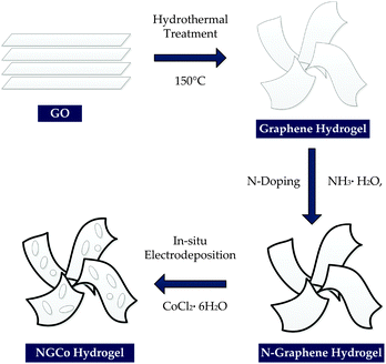
The NG hydrogels were prepared using a three step synthesis method as illustrated in Scheme 1. Firstly, graphene oxide (GO), which was prepared via Hummer's method,14 was converted into a graphene hydrogel by hydrothermal treatment. The second step consisted of nitrogen doping the graphene hydrogel which occurred simultaneously in the hydrothermal treatment due to the presence of a nitrogen containing precursor. The nitrogen containing precursor used in this study was ammonia (NH3·H2O). The third step involved addition of CoPi nanoclusters into the hydrogel material. This was done using in situ electrodeposition in a cobalt-containing potassium phosphate (KPi) buffer solution. For electrochemical testing, the NGCo hydrogel was deposited on a nickel foam (NF) substrate to form a 3D electrode (denoted as NGCo-NF).
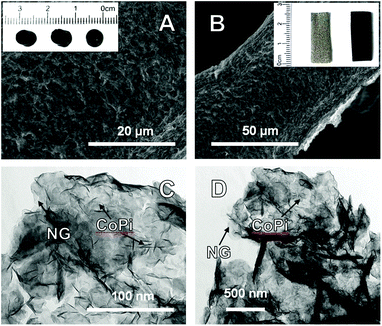
The optical image in the inset of Fig. 1A shows that the NG hydrogels form a self-supporting cylinder of approximately 5 mm in diameter and 10 mm in length. The hydrogels contained 98 wt% of water and 2 wt% of the NG catalyst material, indicating that they are highly hydrophilic. The morphology of the NGCo-NF electrodes was examined using scanning electron microscopy (SEM; Fig. 1A and B). The NGCo hydrogel exhibits a well-connected 3D structure with rich porosity and microstructures similar to that of individual graphene (Fig. S1A, ESI†) and some recent studies.9
The composition of the NGCo hydrogel was then examined using transmission electron microscopy (TEM; Fig. 1C and D). By comparing with those of individual N-doped graphene (Fig. S2, ESI†), it is obvious that cobalt species have been deposited onto mono and few layer graphene sheets. The TEM images also show that the graphene sheets have a tendency to wrinkle and fold over themselves. The degree of wrinkling and folding increases moving inward from the edge of the sheet. This morphology supports the presence of polar functional groups within the graphene sheet that are able to interact with each other and form an interconnected 3D structure.15
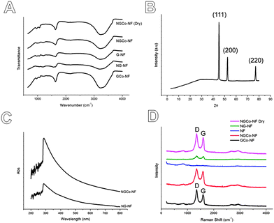
Fourier Transform Infrared Spectroscopy (FTIR; Fig. 2A) confirms the presence of these hydrophilic functional groups, such as carboxyl (–COOH, 1700 cm−1), hydroxyl (–OH, 1250 cm−1) and amine (–NH, 3300 cm−2), which may act as the anchoring sites for the deposition of CoPi nanoclusters on graphene sheets.13 This conclusion is also supported by X-ray Photoelectron Spectroscopy (XPS, Fig. S2, ESI†) of the N-doped graphene hydrogel, which revealed that it contains some functional groups such as –COOH, –OH, as well as two kinds of nitrogen structures, i.e., pyridinic N and pyrrolic N. Therefore, the amine group in FTIR originates from pyridinic N and pyrrolic N structures. Moreover, the X-ray powder diffraction (XRD; Fig. 2B) pattern revealed broad amorphous features within the electrodeposited material. The only peaks revealing a crystalline structure are those associated with the nickel foam (ICDD PDF Card 87-0712). As previously found,13 this shows further support that cobalt forms an amorphous phase when electrodeposited in this manner.
With the absence of a crystalline structure to analyse, the composition of the NGCo was analysed by energy-dispersive X-ray spectroscopy (EDS; Fig. S3, ESI†). Apart from peaks owing to the nickel from the nickel foam substrate, EDS shows the presence of three main peaks caused by oxygen, cobalt and phosphorous which confirms the deposited cobalt phosphate onto the graphene sheets. Elemental mapping was also carried out to detect the distribution of components within the hydrogel. The elemental mappings show a homogeneous distribution of each elemental component in the hydrogel (Fig. S4, ESI†). The ultraviolet-visible (UV-Vis) spectra (Fig. 2C) of the NGCo-NF materials show a characteristic peak at 287 nm. This peak is slightly upshifted in comparison to the spectra of individual nitrogen-doped graphene on nickel foam (denoted as NG-NF) where the peak locates at 286 nm. This upshift could be caused by the strong interactions between the graphene and the CoPi nanoclusters.
Raman spectra (Fig. 2D) of NGCo samples supported on nickel foam were analysed and showed the existence of D and G bands. The D band was located at 1352 cm−1 and the G band was located at 1592 cm−1 which is consistent with previous studies.9,16 A broader 2D peak was also observed at approximately 2700 cm−1 which is consistent with that reported for few layer N-graphene.16 In addition, other broad peaks were examined at around 200 and 860 cm−1 which were found to be attributed to the nickel foam. The Raman spectra show that the intensity of the D band in those samples with nitrogen doping (NG and NGCo) is lower than that of CoPi deposited on individual graphene hydrogels (GCo, ID/IG = 1.44; see Table S1, ESI†). The ID/IG values for NG and NGCo were 1.15 and 1.13 respectively indicating a greater degree of graphitisation for those samples that were nitrogen doped. The slightly lower ID/IG value for NGCo compared to NG also indicates a reduction in structural defects in the material.
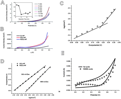
The amount of cobalt deposited onto the NG hydrogels was calculated by integrating the chronoamperometric plots to obtain the passed charge and using Faraday's law. The amount of deposited cobalt was found to follow a fairly linear increase with increasing deposition time (Fig. S5A, ESI†). The OER performance of the NGCo materials was first tested by linear sweep voltammetry (LSV) using a neutral KPi electrolyte. LSV (Fig. 3A and Fig. S3B, ESI†) shows that samples which underwent a deposition time of 1 minute achieved the best performance, achieving a catalytic current density of 3.6 mA cm−2 at 1 V vs. Ag/AgCl. The performance then quickly drops for samples which underwent deposition times of 5 minutes or longer durations which only achieve the catalytic current density of ∼2 mA cm−2 at 1 V vs. Ag/AgCl.
To characterise the performance of these NGCo materials, the effects of N-doping were first tested. Using LSV (Fig. 3B), the performance of NGCo was compared against the performance of GCo and IrO2 (Fig. S6, ESI†). The NGCo demonstrated smaller onset potentials of 243 mV compared to 265 mV for GCo and 520 mV for IrO2. On the other hand, Tafel plots feature the linear portions of LSV at low overpotential fitted according to the Tafel equation (η = b![[thin space (1/6-em)]](https://www.rsc.org/images/entities/char_2009.gif) log
log![[thin space (1/6-em)]](https://www.rsc.org/images/entities/char_2009.gif) j + a, where η is overpotential, j is the current density, and b is the Tafel slope) (Fig. 3C and D). The Tafel slope of NGCo is smaller than that of GCo (550 mV Dec−1vs. 699 mV Dec−1) which corresponds to more favourable reaction kinetics. Therefore, N-doping favours smaller onset potentials and higher OER activity. Cobalt nanoclusters deposited on nickel foam, as can be seen from Fig. 3B, contribute relatively little OER activity compared to the GCo and NGCo. Therefore, the majority of OER activity arises from synergistic effects between CoPi and N-graphene hydrogel. The NGCo electrodes also showed relatively good stability with less than 30% attenuation across anodic current after 1000 continuous cycles of cyclic voltammetry (CV) tests (Fig. 3E). Furthermore, after a 12 hour amperometric test, LSV before and after (Fig. S7, ESI†) showed an insignificant change in current density (at 1 V vs. Ag/AgCl).
j + a, where η is overpotential, j is the current density, and b is the Tafel slope) (Fig. 3C and D). The Tafel slope of NGCo is smaller than that of GCo (550 mV Dec−1vs. 699 mV Dec−1) which corresponds to more favourable reaction kinetics. Therefore, N-doping favours smaller onset potentials and higher OER activity. Cobalt nanoclusters deposited on nickel foam, as can be seen from Fig. 3B, contribute relatively little OER activity compared to the GCo and NGCo. Therefore, the majority of OER activity arises from synergistic effects between CoPi and N-graphene hydrogel. The NGCo electrodes also showed relatively good stability with less than 30% attenuation across anodic current after 1000 continuous cycles of cyclic voltammetry (CV) tests (Fig. 3E). Furthermore, after a 12 hour amperometric test, LSV before and after (Fig. S7, ESI†) showed an insignificant change in current density (at 1 V vs. Ag/AgCl).
The performance of the NGCo material was also compared with the results produced in the study by Kanan & Nocera.13 In their study, their ITO catalysts achieved an onset potential of 280 mV and a catalytic current density of 1 mA cm−2 at an overpotential of 410 mV. From the Tafel plot (Fig. 3C and D), it can be seen that the NGCo achieves far better performance with an onset potential at 243 mV and a current density of 1 mA cm−2 occurring at 225 mV. Therefore, the NGCo has a lower onset potential and is far more active toward the OER. This was also the case when compared with the results of other studies involving OER catalysts in a neutral electrolyte.17,18
One aspect of the research is to analyse the effect the source and the amount of nitrogen used in hydrothermal treatment has on OER performance. In order to do this, NG hydrogel samples were prepared using varying nitrogen content by changing the amount of N-precursor used in the hydrothermal treatment of GO. These hydrogel samples were prepared as free standing hydrogels without electrodeposited CoPi. The different mass percentages of N-precursor used in the hydrothermal mixture are outlined in Table S2 (ESI†). To assess the effect that different nitrogen content and precursor have on OER activity, electrochemical characterisation of the NG hydrogels without cobalt was performed using a standard three-electrode cell (Fig. S8A, ESI†). It was found that samples prepared with a hydrothermal mixture containing 75 wt% ammonia (denoted 75-NH3) performed far better than any other sample (Fig. S9, ESI†). In regard to how the nitrogen source affects OER performance, CV plots also showed that the performance of 75-NH3 increased steadily by 45% after 20 cycles (Fig. S10A, ESI†), and remained stable for at least 200 cycles. This observed increase in current density throughout the first few cycles may be attributed to activation of the catalyst within these first few cycles. In comparison, the best performing NG hydrogel which used ethylenediamine precursor (45-EDA) was seen to show a decrease in catalytic performance after 20 cycles (Fig. S10B, ESI†). As EDA has two amine groups and is a bigger molecule to NH3, it is possible that addition of EDA to the graphene structure could cause a greater degree of defects and deformation between one or multiple sheets of graphene. This could be the reason for the lesser performance of hydrogels N-doped using EDA precursor.
The reasons for the good performance of the NGCo material may be the synergistic effect between CoPi nanoclusters and the N-doped graphene hydrogel substrate. On one hand, CoPi nanoclusters, which have intrinsically high activity toward OER,13 have acted as the main active centres for the catalytic reaction. On the other hand, the excellent structural properties of the N-doped graphene hydrogel can significantly boost the catalytic efficiency. Firstly, the graphene sheet has high conductivity which provides better availability to active centres for enhanced electrode activity. Secondly, the hydrophilic nature of graphene hydrogels and their 3D porous structure may also provide a thermodynamic advantage toward the OER. The high water content and large pores of the materials, facilitating transport of oxygen away from the surface of the materials, can push the equilibrium toward oxygen evolution. Furthermore, tailoring the microstructure by N-doping with nitrogen containing precursors can facilitate access to the active sites and the use of nickel foam as a scaffold for the NG hydrogel also affords large catalyst loadings.
In summary, in situ electrodeposition is a facile and successful technique to introduce CoPi nanoclusters into NG hydrogel materials. This study has further shown that composites formed by the deposition of CoPi species onto conductive materials can act as high performing OER catalysts. The catalyst reported here is significant for the following reasons: (1) it is the first example which demonstrates the use of a graphene hydrogel for synthesising a CoPi based OER catalyst; (2) the synthesised NGCo material has high OER activity and is able to catalyse the OER at low overpotential, ambient conditions and in a neutral electrolyte and (3) it provides a facile, inexpensive and safe methodology for producing these catalysts. NG hydrogels not only provide a substrate for CoPi but the NGCo composite formed outperforms other CoPi based OER catalysts in the literature which highlights a new area of exploration for graphene hydrogels.
This work is financially supported by the Australian Research Council (ARC) through the Discovery Project programs (DP1095861 and DP130104459).
Notes and references
- N. S. Lewis and D. G. Nocera, Proc. Natl. Acad. Sci. U. S. A., 2006, 103, 15729–15735 CrossRef CAS PubMed.
- J. Suntivich, K. J. May, H. A. Gasteiger, J. B. Goodenough and Y. Shao-Horn, Science, 2011, 334, 1383–1385 CrossRef CAS PubMed.
- M. Armand and J. M. Tarascon, Nature, 2008, 451, 652–657 CrossRef CAS PubMed.
- S. Trasatti, Electrochim. Acta, 1984, 29, 1503–1512 CrossRef CAS.
- S. Ardizzone, G. Fregonara and S. Trasatti, Electrochim. Acta, 1990, 35, 263–267 CrossRef CAS.
- X. Wang, X. Li, L. Zhang, Y. Yoon, P. K. Weber, H. Wang, J. Guo and H. Dai, Science, 2009, 324, 768–771 CrossRef CAS PubMed.
- S. Park, Y. Hu, J. O. Hwang, E. S. Lee, L. B. Casabianca, W. Cai, J. R. Potts, H. W. Ha, S. Chen, J. Oh, S. O. Kim, Y. H. Kim, Y. Ishii and R. S. Ruoff, Nat. Commun., 2012, 3, 638 CrossRef PubMed.
- J. Wang, H. X. Zhong, Y. L. Qin and X. B. Zhang, Angew. Chem., Int. Ed., 2013, 52, 5248–5253 CrossRef CAS PubMed.
- P. Chen, J.-J. Yang, S.-S. Li, Z. Wang, T.-Y. Xiao, Y.-H. Qian and S.-H. Yu, Nano Energy, 2013, 2, 249–256 CrossRef CAS PubMed.
- V. H. Luan, J. S. Chung, E. J. Kim and S. H. Hur, Chem. Eng. J., 2014, 246, 64–70 CrossRef CAS PubMed.
- T. Zidki, L. Zhang, V. Shafirovich and S. V. Lymar, J. Am. Chem. Soc., 2012, 134, 14275–14278 CrossRef CAS PubMed.
- V. Y. Shafirovich, N. K. Khannanov and V. V. Strelets, Nouv. J. Chim., 1980, 4, 81–84 CAS.
- M. W. Kanan and D. G. Nocera, Science, 2008, 321, 1072–1075 CrossRef CAS PubMed.
- W. S. Hummers and R. E. Offeman, J. Am. Chem. Soc., 1958, 80, 1339 CrossRef CAS.
- Y. Xu, K. Sheng, C. Li and G. Shi, ACS Nano, 2010, 4, 4324–4330 CrossRef CAS PubMed.
- Z. H. Sheng, L. Shao, J. J. Chen, W. J. Bao, F. B. Wang and X. H. Xia, ACS Nano, 2011, 5, 4350–4358 CrossRef CAS PubMed.
- J. Tian, H. Li, A. M. Asiri, A. O. Al-Youbi and X. Sun, Small, 2013, 9, 2709–2714 CrossRef CAS PubMed.
- H. Lin, Y. Zhang, G. Wang and J. B. Li, Front. Mater. Sci., 2012, 6, 142–148 CrossRef.
Footnotes |
| † Electronic supplementary information (ESI) available: Experimental details and material characterization. See DOI: 10.1039/c5nh00002e |
| ‡ A. Vasileff and S. Chen contributed equally to this paper. |
| This journal is © The Royal Society of Chemistry 2016 |


